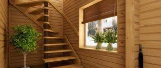
The staircase section of the building is an integral part of all project documentation. This drawing usually shows not only the direction and location of flights and flights, but also their main dimensions. Of course, professional architects are engaged in the construction of such schemes, but if you have already taken up the construction of your house, then it is worth spending time and understanding the main points.
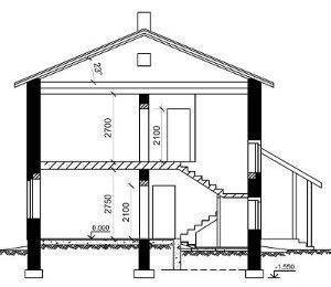
Building sections
General principles of construction
No matter how simple the structure of the house is, it requires a project to be built. A typical project includes a variety of documentation, however, for us, as future home owners, the most interesting will be the drawings that visualize the planned result.
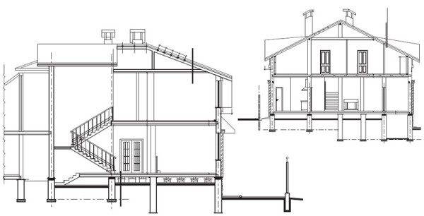
These drawings primarily include facades and sections:
- The facade is an image of the appearance of the structure being erected. As a rule, when building a facade drawing, not only the supporting elements are taken into account, but also the finishing details, which allow you to create a more accurate image of the house.
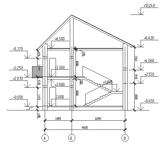
- The section is a graphic representation of the house, mentally divided by a plane into two or more parts. The section drawing shows the objects through which the cutting area passes, as well as the objects that are behind it.
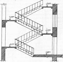
- If the facade drawing gives an idea of how the house will look externally, then along with the plan, a section of the house along the stairs or along another element provides a demonstration of the internal structure of the room.
Note! As a rule, a set of design documentation includes at least two drawings: one with a longitudinal section, and one with a transverse section. If the house has a complex configuration, then the number of such documents will increase accordingly.
Requirements for drawings
The drawing of the section along the stairs must be performed according to certain rules:
- For the sake of clarity, the cutting plane is located in such a way that it passes not only through one of the flights of stairs, but also through window or doorways. If this is not possible, the development of an additional circuit is carried out.
- Construction begins with drawing the centerlines of the supports and load-bearing walls. On top of the axes we draw the main walls (external and internal), bind the elements to the split axes.
- We mark the vertical lines: the floor level on the first and second floors, the attic floor, the ridge of the roof, the bottom of the foundation.
Note! When constructing a diagram, the materials from which it is planned to manufacture certain structural elements are depicted using symbols.
- Outside the contour of the main building, auxiliary lines are drawn, on which the dimensions of the openings (window and door), the overall dimensions of the structure, and the marks of the depth of the foundation are indicated.
Naturally, these are only the most general requirements. If you plan to make a drawing with your own hands, then you should start learning the rules from scratch, since in projects every detail matters, from the type and thickness of the line to the placement of numbers indicating the size. Well, if you only need a drawing of the staircase section for a general presentation, then the information presented above is quite enough to obtain a satisfactory result.
Ladder drawing technology
Necessary information
In this section, we will show you how to draw a sectional staircase. The instructions given will be quite simple and detailed, therefore, even those who have not previously dealt with engineering graphics can cope with this task.
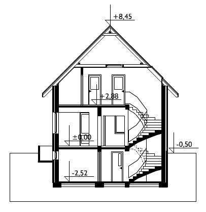
For effective construction, we need to refine a series of data. Among them:
- The height of the rise from the floor level of the first floor to the floor level of the second.
- The configuration of the stairs (the number of flights, the relative position, the presence and dimensions of the intermarch sites).
- The slope angle of the lifting part, which will help us determine the length of the future flight of stairs.
- The number and size of the stairs.
Note! If, in addition to the section, you will build a plan, then you will also need information about the width of the staircase and the dimensions of each individual flight.
Example of calculating parameters
To build the most detailed and accurate drawing, which will depict a staircase in section, it is necessary to perform calculations of the dimensions of individual elements. So that you can master this technology, below we will give an example for a small private house.
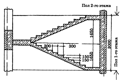
So, let's calculate the dimensions of the structure for such initial data:
- Floor height h = 3000 mm.
- The width of one march is a = 1050 mm.
- Tread width x = 300 mm.
- Riser height y = 150 mm.
- The slope of the lifting part - 1: 2
We start the calculation:
- Staircase width: 2 x 1050 + 100 (gap between flights) = 2200 mm.
- The height of one march is 3000/2 = 1500 mm.
- The number of risers in the march is 1500/150 = 10.
Note! The upper tread in this case will coincide with the landing (it is called a frieze step), and therefore there will be 9 treads in each march.
- The length of the horizontal overlap of each march: 300 x 9 = 2700 mm.
- We lay staircases at least 1200 mm wide, since they should not be narrower than each of their flights.
- The total length of the staircase will be equal to:
- 2700 + 2 x 1200 = 51000 mm.
These values will form the basis of our drawing.
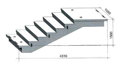
An image of a staircase in a section of a building
The construction of a staircase diagram in a sectional drawing of a house is carried out in the following sequence:
- First, we make a schematic representation of the house itself. The requirements for such a document were outlined in our article a little earlier.
- We divide the height of one floor into segments, the size of which is equal to the height of the riser.
- Through the points obtained as a result of dividing, we draw axial lines strictly horizontally.
- We divide the width of each march into segments, the length of which corresponds to the size of the tread.
- As in the previous case, we draw centerlines through the obtained points.
At this stage, we have a mesh of intersecting lines. Along these lines, we can build the contour of the stepped part of our future staircase:
First, we draw the boundaries of the steps on the drawing with the main lines. In this case, it is very important to ensure that the extreme points of the marches coincide vertically, i.e. were in the same plane.
After drawing the main lines on the section diagram, you can designate the structural elements of the stairs that will affect the process of erection and operation of the building.
So, we can separately depict:
- Bearing elements of the stairs (stringers, bowstrings) in the appropriate scale.
- Entrance areas to the stairs.
- Railing.
- Handrails.
- Fencing.
Strictly speaking, the official project documentation does not provide for the image of such details, however, if you make a diagram for yourself or for workers, then such trifles will contribute to the highest quality visualization of the final result.
Finally, the dimensions are applied to the drawing:
- Staircase width and length.
- Width and length of individual flights.
- The dimensions of the gap between flights.
- The floor marks of each floor and, separately, the level marks on which the staircases are located.
Particularly noteworthy are the dimensions of the elements that do not fit into the standard grid of staircase solutions.
If you plan to use standard marches based on a reinforced concrete structure, then to facilitate the assembly, you can indicate their marking.
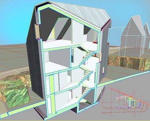
Summing up, I would like to separately note that the use of specialized computer programs (AutoCAD and its analogues) allows us to significantly simplify and speed up the implementation of the task before us. At the same time, if possible, it is better to entrust the construction of the staircase incision to a professional. The thing is that when using this documentation in construction, the cost of an error is too high, because the staircase is one of the most important nodes of the building.
Output
By depicting a section of a staircase, we get an idea not only of its structure, but also of the internal structure of the projected building. That is why it is worth making an effort and building this drawing as efficiently as possible. In the video presented in this article, you will find additional information on this topic.

