The bearing capacity of the screw pile: calculation
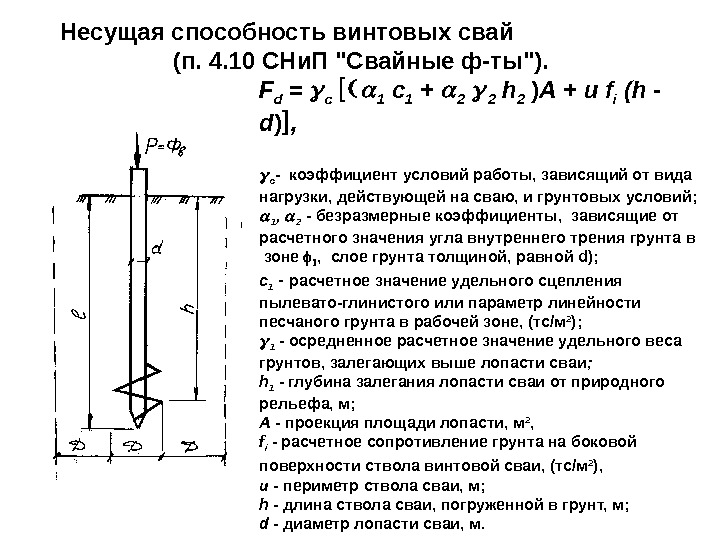
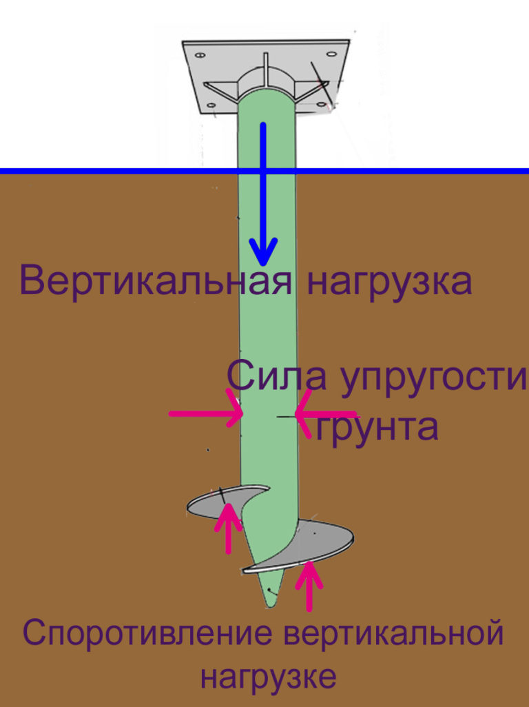
The bearing capacity of screw piles is found by multiplying the bearing area by the bearing force of the soil. Consider this calculation using the example of a screw pile 133 immersed in clay soil:
- First, we find the area of the support. Using the tabular data, we find out that the screw diameter is 30 cm, thus the sole area is: 15x15x3.14 = 706.5 cm².
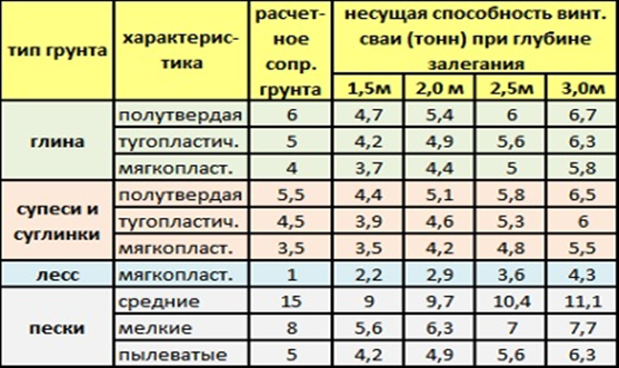
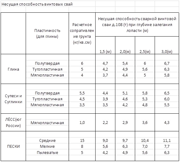
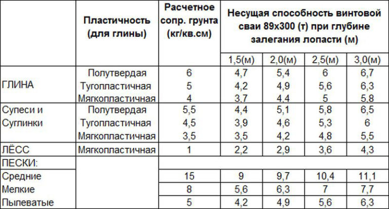
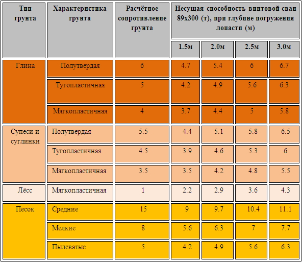
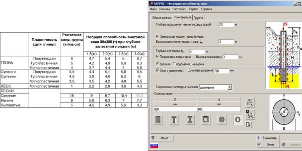
- Now we will use the table to determine the bearing capacity of the soil. For clay soils, it is 6 kg / cm².
- Now we find the bearing capacity of the pile elements: 706.5x6 = 4.2 tons.
Conclusion: one pile element of model 133, with a depth of immersion in clay soil by 2-2.5 m, can withstand a load of 4.2 tons.
Screw piles
How to take into account the reliability of the structure in the calculations?
However, the calculation described in the middle of the article is approximate. It does not take into account the safety factor of parts. To do this, it is necessary to make a final calculation according to the formula: N = F / Y, where N is the required load, F is its approximate value obtained by the above calculation method, Y is the safety factor. The last indicator depends on the correctness of the calculations and the number of pile elements. Its selection is carried out according to the following parameters:
- with the number of elements equal to 5-20 pcs, the coefficient is 1.75-1.4 (in this case, a low grillage on suspended supports should be used);
- the factor 1.25 is used when testing a reference pile element and is approximate;
- for more accurate tests, a factor of 1.2 is used.
Example: in continuation of our calculation for the pile element model 133, we will find the specified bearing capacity: 4.2 / 1.2 = 3.5 tons. This indicator will be used when conducting precise engineering and geological studies. If averaged tabular indicators are used, then the desired value is 4.2 / 1.75 = 2.4 tons.
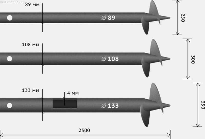
Screw piles: dimensions
Determine the maximum bearing capacity of one pile element
To find the maximum bearing capacity of a single pile element, several data are required at once. For clarity, let's take the following indicators:
- The installation of the piles will be carried out on sandy soils with a bearing capacity of 15 kg / cm².
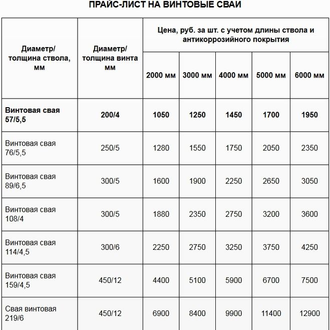
- The foot is model 219 with a foot diameter of 600 mm.
- Since we will use no more than five piles in the field, and the bearing capacity of the soil is determined accurately, we use a coefficient equal to 1.75.
The maximum bearing capacity is calculated as follows:
- We find the support area of the screw pile: 30x30x3.14 = 2826 cm².
- We calculate the approximate bearing capacity: 2826x15 = 42.4 tons.
- Now the exact bearing capacity of the screw piles is determined: 42.4x1.75 = 24.23 tons.
Conclusion: the bearing capacity of one element of screw piles with a support diameter of 300 mm is slightly more than 24 tons. That is, the permissible loads (weight of walls, floors, furniture, etc.) on the supports at such a depth should not exceed 24 tons. As you can see, a correctly calculated bearing capacity of screw piles ensures that our foundation will withstand the weight of floors, walls, wind and snow loads.
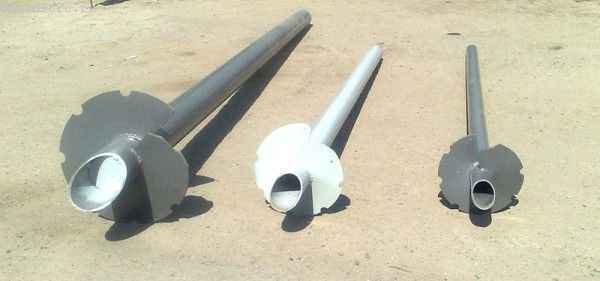
Screw piles
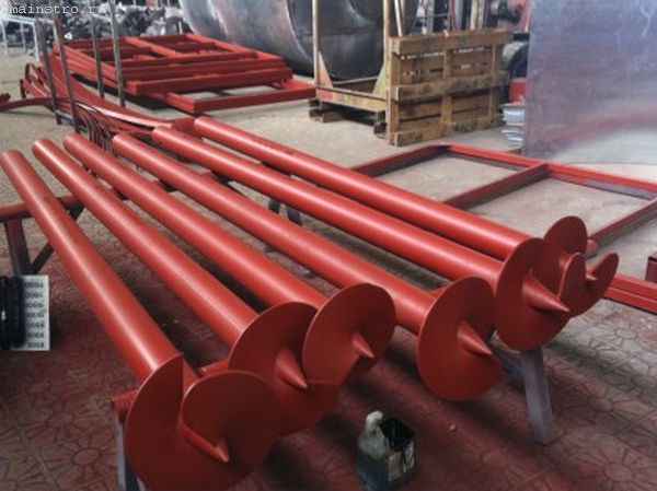
Screw piles
Driven pile length
Distinguish between driven piles, reinforced concrete, concrete, wooden. In shape, they are round, square, T-shaped, I-shaped, hollow.
Standard lengths from three to 16 meters. Minimum for reinforced concrete piles:
- 3 meters for solid.
- 4 meters for hollow.
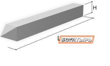
You can use more or less, they are made to order.With a large immersion depth, composite piles are more often used, and the driven method is rarely used, usually a combined one.
The diameter of reinforced concrete piles is up to 80 centimeters, of shells - up to a meter.
See additionally for reinforced concrete piles:
|
|
|
| Examples of calculating a pile foundation
more details |
The cost of pile foundations - examples
watch |
Preparing for calculation
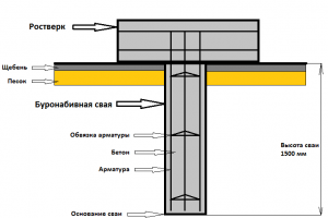 Construction of bored piles
The initial data that will be needed to calculate the bearing capacity of a bored pile is obtained as a result of conducting geological surveys and calculating the total estimated load of the building. These are compulsory stages of the calculation, the implementation of which is justified by the theory of calculating the strength characteristics of bored foundations.
Indicators such as the depth of freezing, the level of occurrence of groundwater, the type of soil and its mechanical characteristics are very important for obtaining an accurate result. Information on the depth of soil freezing is in SNiP 2.02.01-83 *, the data are divided by climatic regions, presented cartographically and in the form of tables.
The calculation of the mass of the building is carried out taking into account the climatic region, the location of the building relative to the rumba of the winds, the average amount of precipitation in winter, the mass of building structures and equipment. This indicator is most significant in the design of the foundation - the data for this part of the calculation, as well as the diagram and calculation formulas can be found in SNiP 2.01.07-85.
Carrying out geology
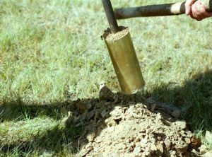 Pit for geological surveys
Conducting geological surveys is a responsible event, and in the mass flow-line construction this is done by geologists. In individual housing construction, an independent assessment of the condition of soils is often carried out. Without experience in conducting surveys of this level, it is very difficult to assess the real state of affairs. The work of a competent specialist for the most part consists in a visual assessment of the state of strata.
To begin with, they arrange shufras on the site - vertical excavations of soil of a rectangular or circular section, a depth of two meters and a width sufficient for a visual inspection of the base of the pit walls. The purpose of the pits is to open the soil in order to access the strata hidden under the top layer of the soil. Geologists measure the depth of the seams, take a soil sample from the middle of each layer, and then observe the accumulation of water at the bottom of the face. Instead of pits, round wells can be arranged, from which a core is taken out with the help of a special device or local samples are taken.
All the data obtained are entered into a summary table. In addition, a profile of the soil section is drawn up, which makes it possible to predict the state of the soil at the points where drilling was not carried out. When self-assessing the foundations, one should be guided by the information provided in SNiP 2.02.01-83 * and GOST 25100-2011, where in the relevant sections the classification of soils with descriptions, methods of visual determination of soil types and characteristics in accordance with the types are presented.
Benefits of screw bases for buildings
A screw pile foundation differs from other types in numerous advantages, resistance to many loads. Among the advantages of such a foundation, the following should be noted:
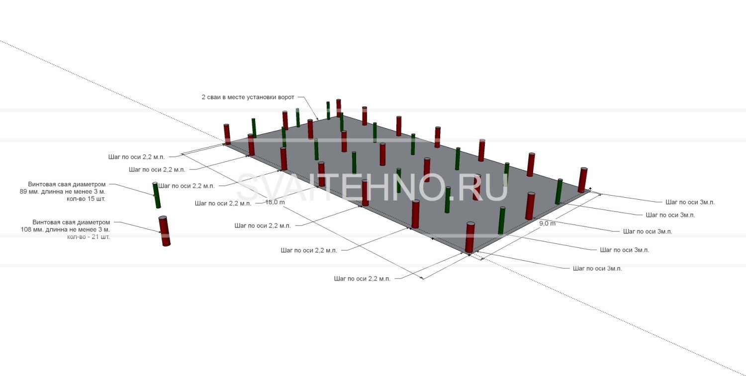
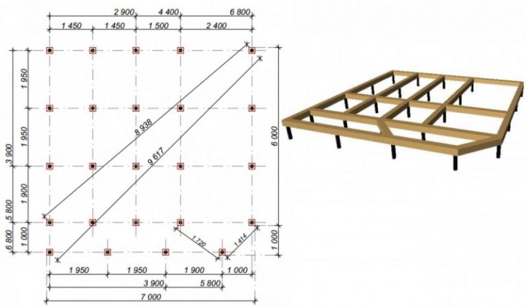
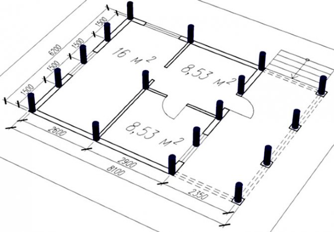
Screw pile laying scheme.
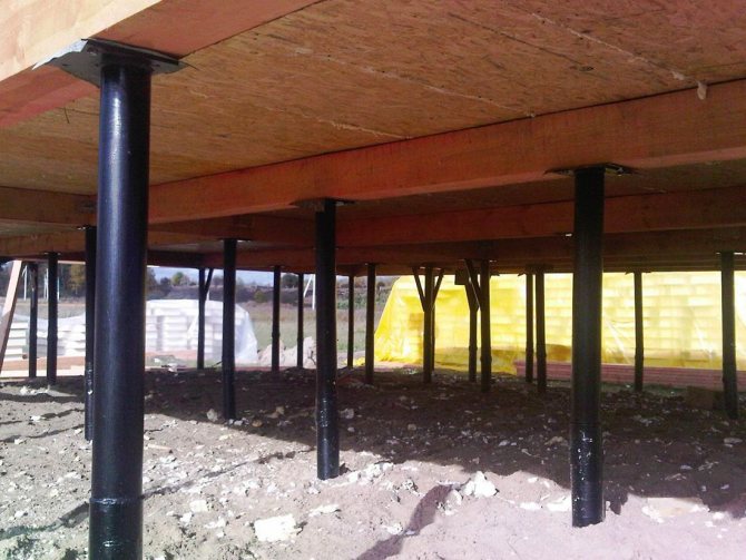
- buildings can be erected under almost any conditions, even on wet and difficult soils, for which other types of foundations are not used. Construction is possible on slopes, on peaty, swampy soils, in places heavily damaged by tree roots;
- the amount of materials used for construction is minimal. Unlike a slab base, for which a large amount of concrete is consumed, only the estimated number of piles poured with concrete is used. A simple but very reliable grillage is arranged on top;
- earthworks are minimized;
- work can be carried out at any time of the year;
- screw supports can be installed even on a slope, with strong changes in the site, since the house itself turns out to be raised above the ground level;
- installation takes only a couple of days, there is no need to wait until the concrete slab dries up and gains strength, the solution is poured only into the cavity of the supports;
- the service life of the foundation on piles is up to 100 years;
- waterproofing is not required, and this is already a significant savings;
- high seismic resistance;
- during installation, it is not necessary to use complex construction equipment, wells for piles are not dug out, since the supports are screwed into the soil with the help of special blades located at one of the ends.
Calculation of the distance between piles
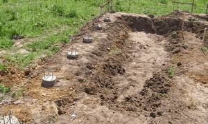 To determine the distance between the piles of a pile foundation, you need to know two values: the required number of piles and the size of the building in plan.
The algorithm for calculating the number of supports is approximately the same for all of their types, therefore it is enough to consider one option - for example, bored piles.
The initial data for the calculation are:
- soil analysis in the construction area;
- the maximum load of the future house on the ground;
- area of the house.
Soil analysis
 You can determine the composition of the soil on the site yourself (if you plan to erect a light building). To do this, at the site of the future foundation, it is necessary to dig several holes with a depth of about 2 meters.
In the process of digging "holes" you will see what type of soil you will come across, and at what depth is a dense layer (for example, hard clay).
You will need this parameter to calculate the length of the pile.
We collect loads
The total ground load is defined as the sum of the weights of all building materials that are supposed to be used in construction, snow and wind loads.
The last two values are normative.
They depend on the region of construction and are determined according to the tables of SNiPs in force in Russia.
Determine the required number of piles
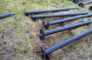 To determine the required number of supports, you must perform the following steps:
- calculate the foot area of one pile;
- the result obtained is multiplied by the resistance (4);
- divide the total load by the product of the sole area and the resistance.
Having received the number of supports, it is necessary to adjust the load: after all, the piles themselves press on the ground. The weight of a bored pile is calculated without taking into account its expansion.
Multiplying the weight of one element by their total number, we get an additional load on the ground.
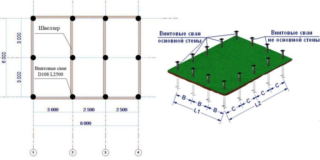
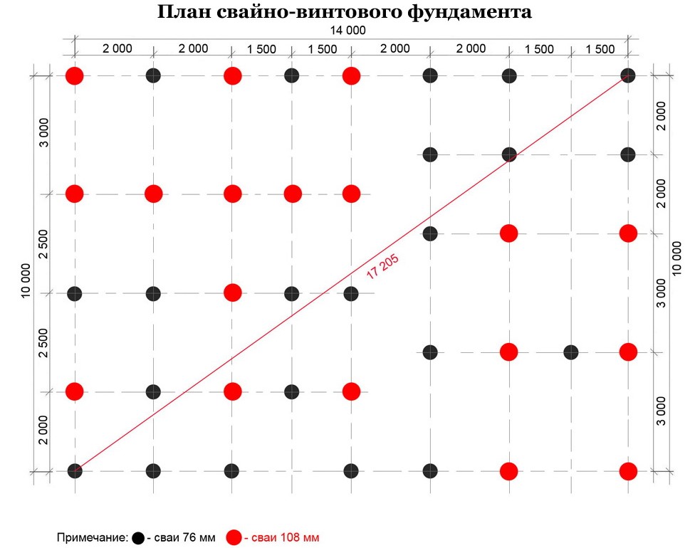
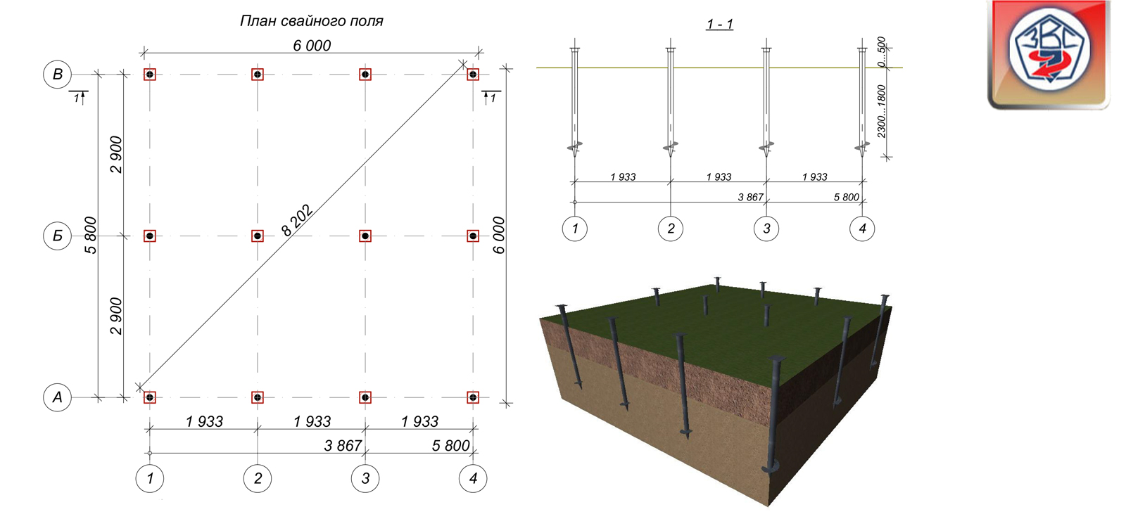
Pile installation step
 How to determine the distance between the foundation piles, knowing their number and overall dimensions of the building?
It seems that there is nothing simpler: the calculation of the distance between the piles for the foundation consists in dividing the perimeter of the building by the number of supports.
But there are some nuances here too - there are minimum and maximum allowable distances between the supports:
- the minimum distance between the bored piles of the foundation along the axes should not be less than three diameters of the support;
- the maximum distance between the foundation piles is from 5 to 6 pile diameters.
There are a few exceptions to the above rule:
- when building on sandy soils, the minimum permissible distance between the concrete foundation piles is 4 diameters. With a decrease in the step, soil overconsolidation occurs, which leads to the complication of installation work;
- wooden piles are installed with a minimum step of 70 cm, regardless of their diameter;
- the minimum allowable step for reinforced concrete supports is 90 cm.

Depending on the type of foundation, piles can be placed in a row or staggered manner. The first method is used in the pile-strip foundation, the second - in the pile-grillage foundation.
Distance between piles pile-grillage foundation should not exceed six column diameters. Otherwise, the support will be subjected to an increased load and work as a single support.This will ultimately lead to the destruction of the grillage and even the collapse of the building.
The optimal distance between the piles of the pile-strip foundation is considered to be 1.5-2 meters.
The maximum allowable spacing depends on the placement of the supports:
- in one row - 1.33 m;
- in two rows - 2.67 m.
Regulations
The main document describing the structure and types of foundations on pile supports, as well as regulating their design and calculation, is SNiP 2.02.03-85 "Pile foundations".
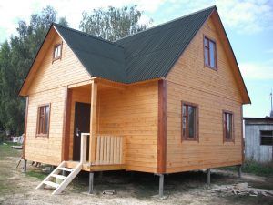 Stilt house
A more modern document, developed not so long ago, is SP 24.13330.2011. In the modern edition of SNiP, no significant changes have been added, although some replacements and clarifications were made after the appearance of new technologies and materials. In case of doubts and significant disagreements, one should, nevertheless, be guided by the joint venture, in which specific examples are given.
The Rules state the main requests for the development of a specific type of foundation - pile.
The joint venture describes various types of supports, engineering and geological characteristics, considers the nuances and particular examples of calculations for newly erected buildings, reconstructed buildings. The provisions of SP 24.13330.2011, as well as SNiP 2.02.03-85, do not apply to pile foundations under construction:
- for structures under dynamic loading;
- in permafrost;
- at a depth exceeding 35 m;
- for structures related to oil refining enterprises.
What is a screw pile
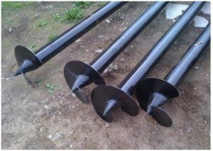 Screw piles
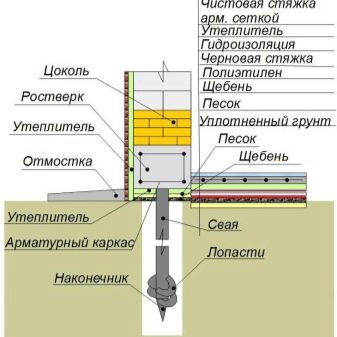
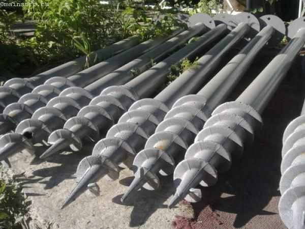
The purpose of this type of supports is to, bypassing weak soil layers, transfer the load from the building through the aircraft to a dense soil base. The passage of the support through the ground is achieved by rotating it. The pile screw goes into the soil like a corkscrew in a cork.
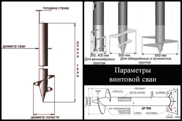
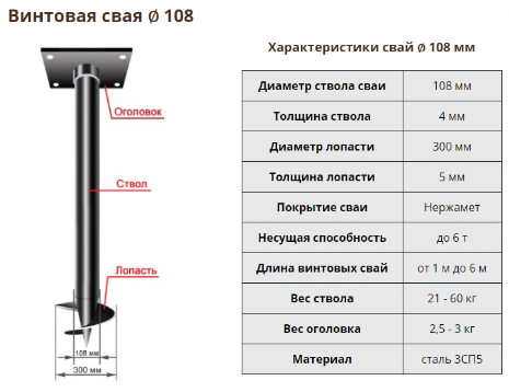
ВС is an all-welded metal structure, consisting of three parts: a barrel (metal pipe), a tapered tip and a blade.
Trunk
The supporting part of the pile is the trunk, which is a metal pipe. The length of the pipe is determined by special calculations based on geological surveys. Prospecting works give an idea of the depth at which dense layers of soil lie. The length of the trunk depends on this. The size of the length of the BC should be such that the end of the pile could enter the supporting soil layer to a depth of 50 - 70 cm.
Tapered tip
The cone-shaped end tip is made cast or all-welded. The sharp end of the pile facilitates the entry of the support into the ground.
Trunks of supports with a cut end
Some manufacturers make racks with a diameter of 58 mm without a sharp tip. The end of the BC is cut at an angle of 45o. The ellipse hole is welded with a steel sheet.
Blades
One or two blades are welded at the end of the helical support. The larger the shaft diameter of the support, the larger the size of the blades. The blades cut into the ground, and when the barrel rotates around its axis, the support moves vertically down to the design mark.
Calculation of the pile foundation
To find out exactly how many screw piles are needed for the foundation, it is possible only after summing up the future loads. Below is a detailed guide. But you should know that it is necessary to take into account not only the basic building structures, but also finishing materials. Door and window blocks, engineering communications have significant weight. It is necessary to add the weight of furniture, large household appliances, boiler and other equipment.
 The final result depends on the type of roofing, additional equipment
Calculator for calculating the total load on the pile-screw foundation
The following are notes for the calculation program:
- The area of partitions and external walls can be calculated personally. For this, use the existing drawings. The data will be more accurate if you subtract the area of the door and window blocks. If this is not done, the strength of the foundation will be created with a margin.At this stage, the main material of building structures is selected in the corresponding column of the calculator.
- Floor area information is useful for calculating floor weights. The material is also indicated here, taking into account the reinforcement, other important details from the list that opens in the corresponding item. Subtract the empty areas for the installation of flights of stairs.
- Next, choose the type of roofing. If there is no specific option, materials that are close in weight are noted. So, for example, a roofing material covering will be approximately equal in weight to a soft bituminous roof with the same number of layers. The weight of the rafter system is added by the program automatically, taking into account the choice made.
- In the cold season, snow load can create significant weight. For accuracy, it is necessary to note the angle of inclination of the slopes in relation to the horizontal.
 Precipitation map that determines the weight of the snow cover
- It is not necessary to enter the data indicated in the figure (loads in kg per sq. M.) Into the calculator. It is enough to indicate the zone in which the property will be built.
- The mass of the grillage made of wood is insignificant, so I take it into account in the calculations, increasing the size of the corresponding walls. If a metal channel or other heavy materials are used to tie the pile foundation, a separate calculation is required.
After checking the data, press the virtual confirmation key. The calculation is performed quickly, without additional user intervention. To find out whether the strength of the supports is sufficient, the obtained value is divided by the bearing capacity of a single part (HC), which is calculated in advance.
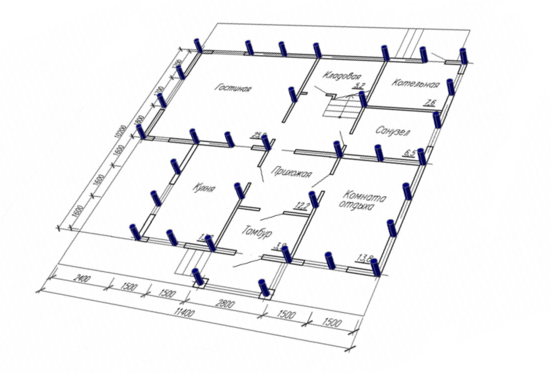
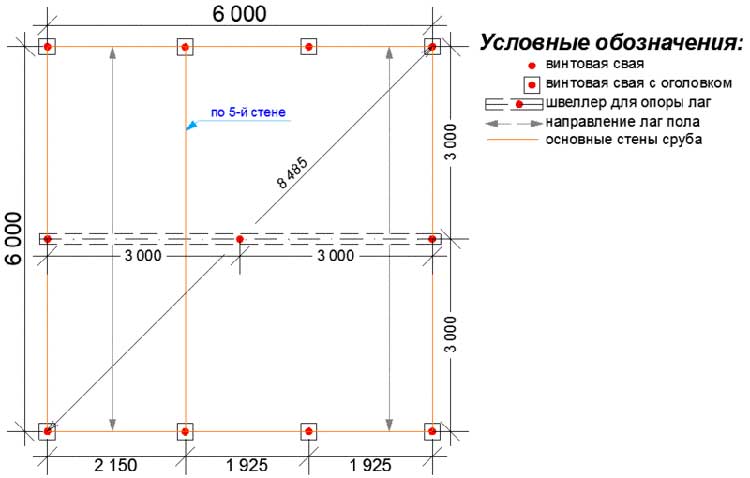
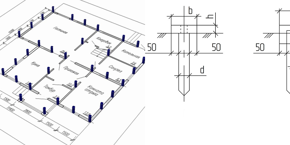
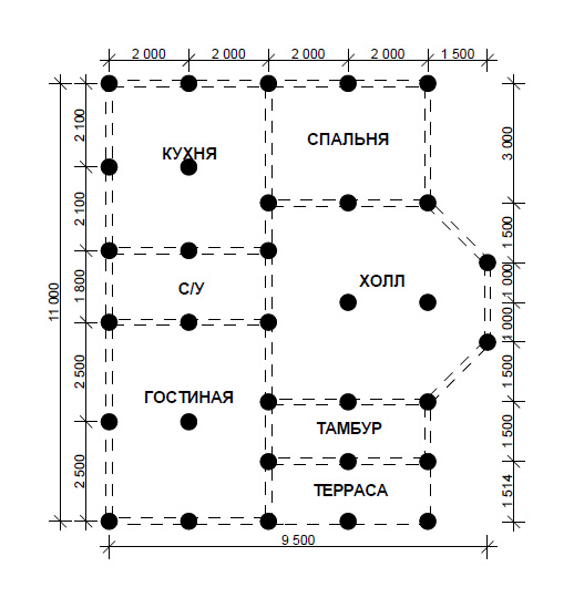
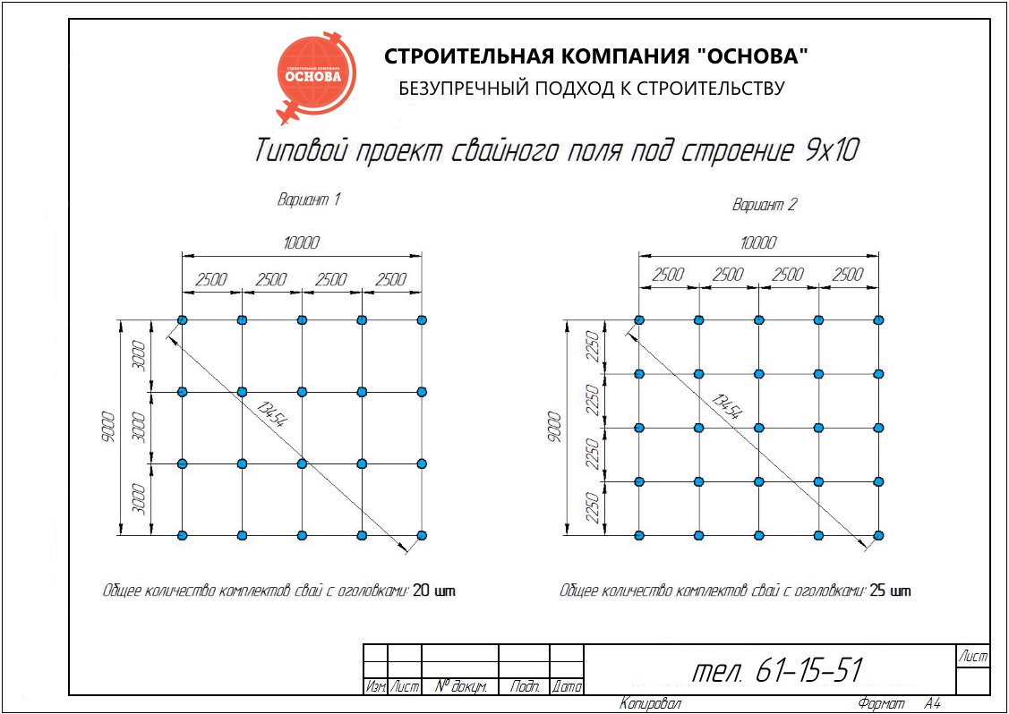
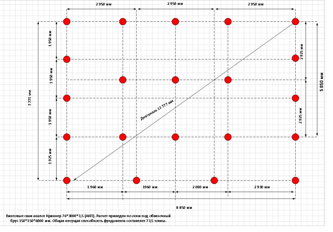
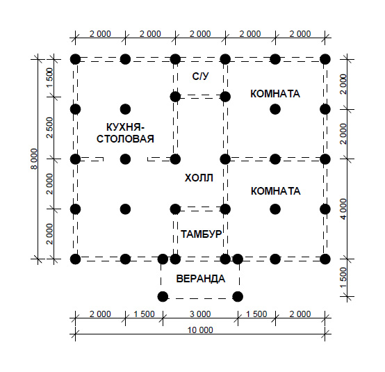
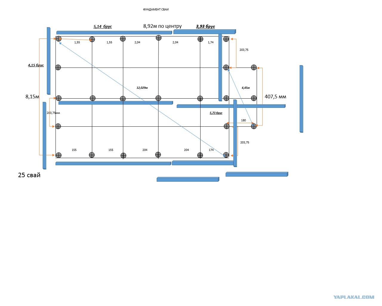
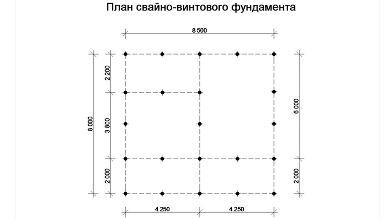
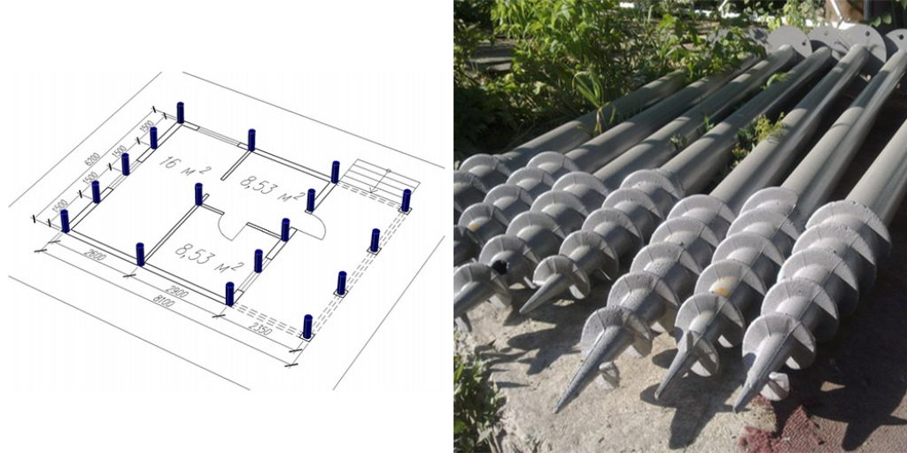
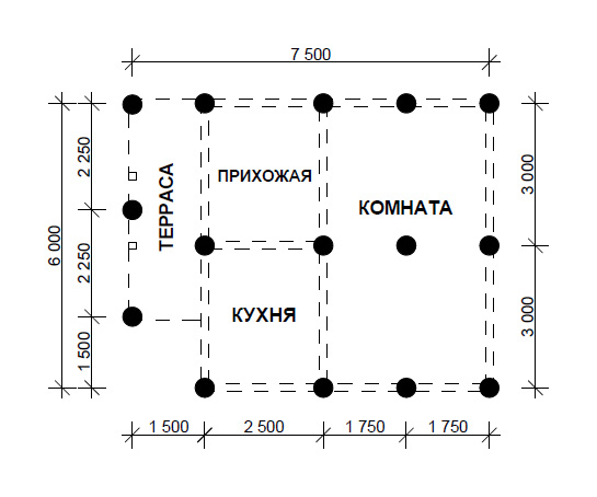
Let us assume that for frame house we got the number of piles equal to 17. This is not the final result yet. Using a drawing with a building outline and walls, distribute the anchor points. They are installed at the junctions of the enclosing structures, in the corners. On straight sections of building structures, piles are installed with a step of no more than 300 cm.
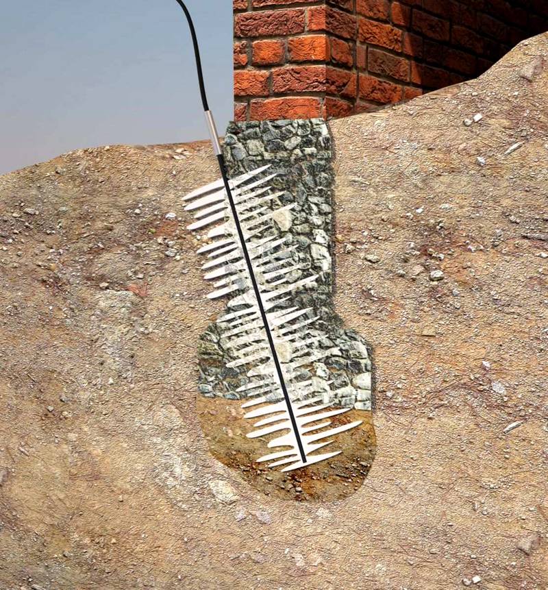 If the calculation is done with a margin, there will be no need to strengthen the "weak" foundation with drilling-injection technologies
The above calculation is used for the design of capital structures. Small outbuildings, fences, and other lightweight structures can be erected on weaker foundations. But we must remember that you will need separate supports for heavy technological equipment. A similar additional reinforcement is installed under a column that holds a large weight, other critical elements of the power frame.
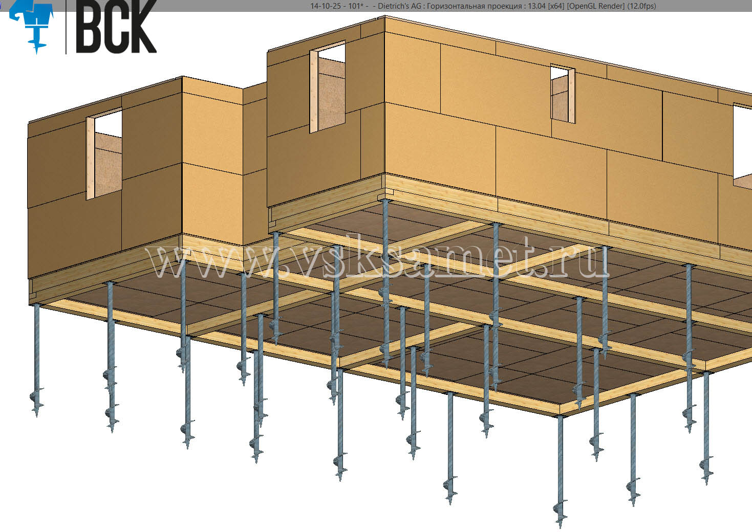
In difficult terrain and on steep slopes, the difference in elevation may be too large. In some cases, piles of different lengths will be needed. They are screwed in so that a margin remains from the design height from 30 to 60 cm. The surplus is marked using a level, cut off one level at a time. Next, the heads are fixed, the grillage is installed in accordance with the selected option.
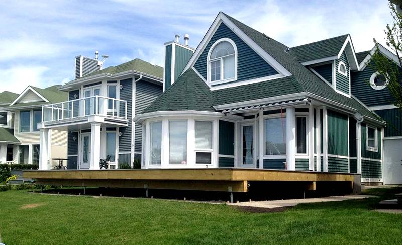 Country house on screw piles

Calculation of the bearing capacity of a screw pile
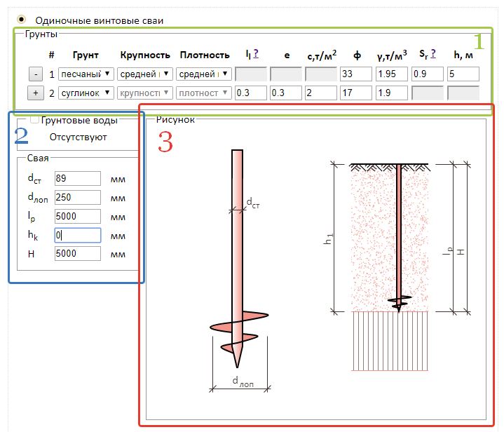
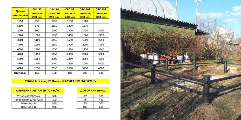
To start calculating the bearing capacity of the screw rack, you need to get the initial data: the calculated resistance of the soil into which the support auger will be immersed, the diameter of the auger (blade), and the aircraft dimensions.
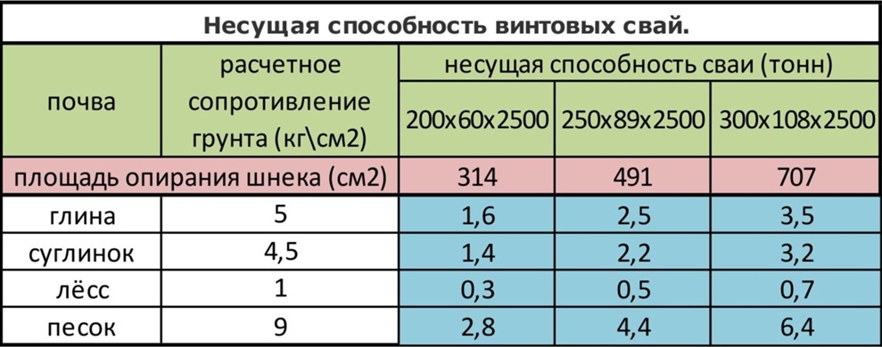
By comparing these data, specialists obtain the design bearing capacity of the aircraft. In the factory, in mass production, screw racks are produced with a length of 2.5 m, a barrel diameter of 58, 89, 108 and 133 mm. Based on numerous tests and calculations, data were obtained that this table displays:
| Support soil layer | Estimated soil resistance, kg / cm2 | 58x2500, mm | 89x2500, mm | 108x2500, mm |
|---|---|---|---|---|
| Clay | 5 | 1,6 | 2,5 | 3,5 |
| Loam | 4,5 | 1,4 | 2,2 | 3,2 |
| Loess | 1 | 0,3 | 0,5 | 0,7 |
| Sand | 9 | 2,8 | 4,4 | 6,4 |
Calculation video foundation on screw piles:
Grillage
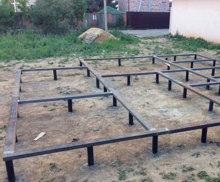
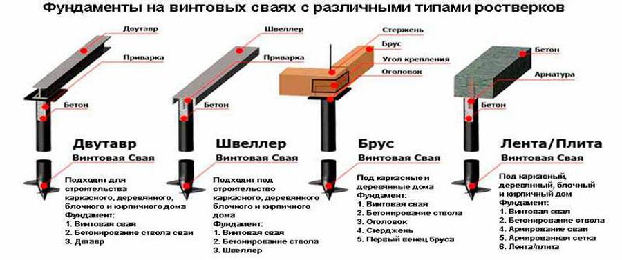
A grillage is a foundation element required to evenly distribute the load exerted by the structure on the foundation. To ensure the reliability of the grillage, it is necessary to calculate a number of parameters, while the type of grillage does not matter.
The calculations include:
- punching force of the foundation;
- punching force acting on each corner separately;
- bending force.
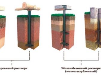

If a high grillage is used, the entire load is applied to the piles. The vertical load acts from below, the deforming load acts from the side. Such calculations are very complex and require professional knowledge. For calculations, you must use the standards of individual construction.
They define the following norms:
- supports can be connected to the grillage in two ways: rigid and free;
- the depth of entry of the pile head into the grillage is at least 10 cm;
- the distance between the ground and the grillage is at least 20 cm;
- the thickness of the grillage cannot be less than the thickness of the walls and is at least 40 cm;
- the grillage must have a height of more than 30 cm;
- the grillage is reinforced with longitudinal and transverse reinforcement with a rod section from 10 to 12 mm.

