Foundations for metal columns
Drawing of a reinforced concrete foundation for a metal product
Monolithic reinforced concrete foundations are made for metal columns.
The column supports are equipped with anchor bolts to secure the column shoe. They are made solid, without glasses. The upper part of the column is positioned so that the metal column shoe and the top of the anchor bolts are hidden.
If the design provided for the deepening of metal columns more than 4 m, then in this case prefabricated reinforced concrete pillars are used, which are produced in the same way as two-branch columns. These elements are fixed from below in the base glass, and their upper parts are fixed with anchor bolts. The foundation for adjacent columns is mounted in common even when they are made of different materials (reinforced concrete and steel).
Calculation of foundations
Vertical load at the level of the planned ground elevation N = 251.58 kN, Nn = 211.37 kN.
The conditional design resistance of the base, composed of gravel-pebble soil, is determined according to table. 45/16 / Ro = 0.6 MPa.
The weight per unit volume of the foundation on its edges is gmt = 20 kN / m3.
Heavy concrete, class B 20; Rbt = 0.9MP; Rb = 11.5 MPa; rb2 = 1;
fittings of class A-II; Rs = 280 MPa.
The height of the foundation is preliminarily taken equal to 40 cm, the depth of the foundation is 40 cm.
The area of the foot of the foundation is determined by the formula 2.6:
A = N / (R0 -gmth) = 251.58 / (0.6 103-20 0.9) = 1.34 m2.
The size of the side of the square sole is a = v1.34 = 1.15m.
The base slab is taken from monolithic reinforced concrete with an area of A = 1.21.2 = 1.44 m2.
Base plate weight:
Gf = Af · h · = 1.44 · 0.4 · 25 = 14.4 kN.
Soil weight on foundation cutoffs:
Ggr = (1.2 1.2-0.4 0.4) 0.5 21 = 23.1 kN.
The average pressure under the foot of the foundation is determined by the formula 2.24:
Rav = N + Gf + Ggr / Af = 211.37 + 14.4 + 23.1 / 2.56 = 98.97 kN / m2.
We determine the calculated loads from the weight of the foundation and soil on its edges:
Gfr = cGf = 1.1 * 14.4 = 15.84 kN.
Ggrr = 1.2 23.1 = 27.72 kN.
The average design pressure under the foot of the foundation is determined by the formula 2.24:
pcrp = Np + Gfr + Gpr + Ggrr / Af = 251.58 + 15.84 + 27.72 / 1.44 = 204.9 kN / m2.
The transverse force at the edge of the column is determined by the formula 2.25:
QI = pcrp · b · (l-lk / 2) = 204.9 · 1.2 · (1.2-0.4 / 2) = 245.88 kN;
The calculation for the action of the lateral force can be omitted if the conditions 2.26 are met:
QI b3 Rbt b ho, where
b3 = 0.6 - coefficient for heavy concrete;
Rbt = 0.9 MPa (see clause 2.2.);
ho = 0.4 m,
QI = 245.88 kN 0.6 · 0.9 · 103 · 1.2 · 0.4 = 259.2 kN.
We finally accept a foundation with a height of 40 cm,
With an increase in the thickness of the slab, the condition is fulfilled, therefore, the installation of working reinforcement is not required, and the calculation for the shear force is not performed.
When checking condition 2.27:
Q = pcrp b 1.5 Rbt b ho2 / c, where
c = 0.5 (l-lk-2ho) = 0.5 (1.6-0.4-2 0.86) = - 0.26
the length of the projection of the oblique section under consideration.
We got that c0, therefore, inclined cracks are not formed on the foundation slab.
The punching shear design is performed according to the formula 2.28:
F bRbt houm, where
F = Nр-рсрp · A = 251.58-245.88 · 1.44 0
A = (lk + 2ho) (bk + 2ho) = (0.4 + 2 0.4) (0.4 + 2 0.4) = 1.44 m2
the area of the base of the punching shear pyramid.
Since the punching force is F 0, this means that the size of the punching shear pyramid is larger than the dimensions of the foundation, that is, the punching shear strength of the foundation is ensured.
Determine the design bending moments in the sections according to the formula 2.31:
MI = 0.125 pcrp (l-lk) 2b = 0.125 * 245.88 (1.2-0.4) 2 * 1.2 = 23.6 kN * m;
Sectional area of reinforcement
ASI = MI / 0.9h0RS = 23.6105 / 0.940280 (100) = 7.33 cm2;
We accept a non-standard welded mesh with the same working reinforcement in both directions from 8 rods 12 A-II with a step s = 15 cm (AS = 9.05 cm2).
Percentage of reinforcement of design sections
I = ASI * 100 / bI * h0 = 9.05 * 100/120 * 40 = 0.17 0.05%;
The elastic-plastic moment of resistance of the foundation section at the column face according to the formula 2.37 is equal to:
Wpl =
Wpl = 1.2 0.42 = 0.256 m3.
From table 4.4 we find the calculated tensile strength for the second limit state groups Rbtn = 1.4 MPa.
Cracking point:
McrcI = 1.4 0.256 = 0.358 MN m
We check the fulfillment of condition 2.39:
M Mcrc, where
M is the moment in the cross-section of the foundation from the standard load.
MI = 0.125 204.9 (1.2-0.4) 2 1.2 = 19.67 kN m McrcI = 0.358 MN m.
Consequently, cracks do not appear in the foundation body.
Intermediate calculations of the base load on the ground
The general indicator of the load created by the strip support on the soil is calculated as follows: the volume of the foundation is multiplied by the density of the material embedded in its foundation, and divided by a square meter of the base area. In this case, the volume should be calculated as the product of the placement depth by the thickness of the support layer.
As a rule, at the stage of preliminary calculations, the last indicator is taken as the thickness of the side walls.

- Base area - 20 square meters, placement depth - 80 cm, base volume 20 x 0.8 = 16 cubic meters.
- The weight of the base, made of reinforced concrete, is: 16 x 2500 = 40,000 kg.
- Total ground load: 40,000/20 = 2,000 kg / sq. M.
Calculation of an eccentrically compressed column by conditional flexibility.
Oddly enough, but for the selection of the cross-section of an eccentrically compressed column - a solid bar, there is an even simpler formula:
F = N / φeR (4.1)
where φe - the coefficient of buckling, depending on the eccentricity, it could be called the eccentric coefficient of the longitudinal deflection, so as not to be confused with the coefficient of longitudinal deflection φ. However, the calculation according to this formula may turn out to be more time-consuming than according to the formula (3.2). To determine the coefficient φe you still need to know the meaning of the expression ezF / Wz - which we met in formula (3.2). This expression is called relative eccentricity and is denoted by m:
m = ezF / Wz (4.2)
After that, the reduced relative eccentricity is determined:
mef = hm (4.3)
where h is not the section height, but the coefficient determined according to table 73 of SNiPa II-23-81. I do not give this table here. I'll just say that the value of the h coefficient varies from 1 to 1.4; for most simple calculations, you can use h = 1.1-1.2.
After that, it is necessary to determine the conditional flexibility of the column λ¯:
λ¯ = λ√‾ (Ry/ E) (4.4)
and only after that, according to Table 3, determine the value of φe:
Table 3. Coefficients φe for checking the stability of eccentrically compressed (compressed-bent) solid-wall rods in the plane of the moment, which coincides with the plane of symmetry.

Notes: 1. Values of the coefficient φe increased 1000 times 2. Φ valuee should take no more than φ.
Now, for clarity, let's check the cross-section of the columns loaded with eccentricity, according to the formula (4.1):
4.1. The concentrated load on the columns, marked in blue and green, will be:
N = (100 + 100) 5 3/2 = 1500 kg
Eccentricity of load application e = 2.5 cm, buckling coefficient φ = 0.425.
4.2. We have already determined the value of the relative eccentricity:
m = 2.5 3.74 / 5.66 = 1.652
4.3. Now we determine the value of the reduced coefficient mef:
mef= 1.652·1.2 = 1.984 ≈ 2
4.4. Conditional flexibility with the adopted flexibility coefficient λ = 130, steel strength Ry = 200 MPa and the modulus of elasticity E = 200000 MPa will be:
λ¯ = 130√‾ (200/200000) = 4.11
4.5. According to table 3, we determine the value of the coefficient φe≈ 0.249
4.6. Determine the required column section:
F = 1500 / (0.249 2050) = 2.94 cm2
Let me remind you that when determining the cross-sectional area of a column using formula (3.1), we got almost the same result.
Tip: In order for the load from the canopy to be transmitted with minimal eccentricity, a special platform is made in the supporting part of the beam. If the beam is metal, from a rolled profile, then it is usually enough to weld a piece of reinforcement to the bottom flange of the beam.
And yet, any deviation of the column from the vertical with one rigidly clamped support at the bottom will lead to the appearance of an additional bending moment in the lower sections of the column. In this case, for columns of small cross-section, such a deviation will be more significant than for columns of large cross-section. Theoretically, the influence of this moment can be taken into account in the calculations, however, the occurrence of an additional bending moment due to possible subsidence of the foundation is rarely taken into account, and therefore the larger the section is taken for the column, the more reliable the structure will be.
P.S.I perfectly understand that it is not easy for a person who first encountered the calculation of building structures to understand the intricacies and features of the above material, but you still do not want to spend thousands or even tens of thousands of rubles on the services of a design organization. Well, I'm ready to help you. For more details, see the article "Make an appointment with the doctor."
And yet, recently there have been a lot of trolls asking tricky questions. In principle, I do not mind, ask. But the response can be tough.
Varieties
The material allows you to get various intricate shapes from it, however, many metal columns have a cross-section in the form of an I-beam, rectangular or round pipe. Section dimensions are calculated by strength (usually compression) and stability calculations. The latter characteristic depends on the presence of connections, half-timbered racks, etc.
Depending on the design solution, the columns can have a constant, stepped and composite section. The constant section structure is a single bar that is used in frameless buildings, warehouses and hangars. It can accommodate equipment with a maximum lifting capacity of 20 tons.

Stepped columns are designed for the installation of equipment with a lifting capacity of more than 20 tons. Thanks to a special section, their bending stiffness and stability are improved. This structure has two load-bearing branches: the main one and the crane one.
Composite metal columns are rarely used, and can take different loads (relative to the axis). They are needed for: - installation of cranes at a low height; - installation of cranes in several tiers; - reconstruction of buildings.
Column installation
The installation of metal structures should be carried out so that the deviations along the axes are not more than permitted by SNiP (especially for milled surfaces). Simple columns are installed entirely, and heavy ones are assembled from composite elements. To mount, they must be grabbed, lifted, brought to the supports, aligned and secured. To grip structures, slings are used, under which pads are placed (for example, made of wood). Lifting is done by turning or sliding.
There are several ways of supporting the base on the base (the nodes of the metal columns can be seen below): - on its surface without grouting, - on steel plates with grouting; - on beams, rails (you will need to grout the base with a solution).
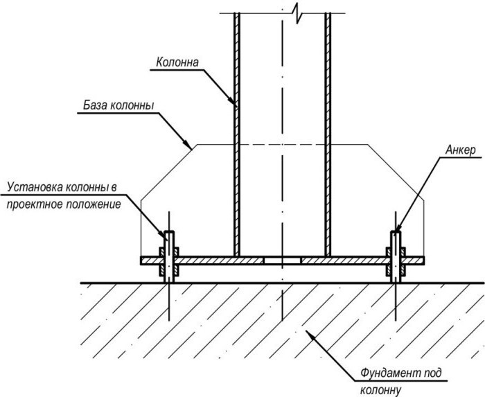
In practice, a simpler installation method is used. In this case, the shoes are installed on steel pads welded to each other, and fastened to the bottom of the columns. As soon as the structures are installed and fixed, they are poured with mortar.
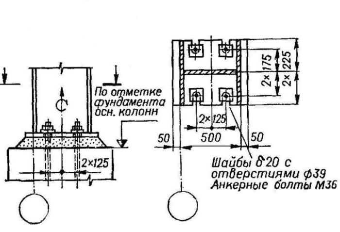
The installation of columns involves careful alignment using geodetic instruments and plumb lines. At the same time, their marks, verticality and position in the plan are checked. Anchor bolts are used to fasten the structures: you will need 2-4 pcs. for columns up to 15 m high. Additional stability will be provided by the braces, which are removed after final fastening. Higher elements are additionally reinforced with struts, temporary ties and struts. To obtain a stable frame, it is better to mount the columns together with the crane beams.
The process of building a foundation on metal pipes.
First, you need to prepare the site on which the foundation will be erected. Places where pipes will be inserted into the ground can be marked with pegs. Then they dig a hole about 80 cm deep. This stage is preparation for drilling. The number of pipes is determined based on the developed project of the house. If, according to the project, there will be a furnace in the house, then it is necessary to provide for four more steel pipes. Then you take a drill with a nozzle, the diameter of which exceeds the diameter of the pipe by 5 cm. The stage of soil drilling begins. If there are a large number of roots in the ground under the foundation, then it is worth cutting them with the help of a previously prepared piece of reinforcement with a welded hatchet at the end.
Determine the drilling depth. If the surface of the site is flat, then this stage will not cause you any difficulties. The main thing to remember is that the drilling depth must necessarily be below the freezing depth. If the surface of the site is uneven and the place allocated for the foundation is too low, then it is worth adding soil. It is necessary to measure the highest point of the site and add the size to which the pipes should be removed from the ground. In fact, this is the height of the metal foundation.
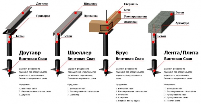
Immediately after drilling, the hole is covered with sand and then gravel. The thickness of each layer should be about 15 cm. Then a "pillow" is poured - a mixture of cement and gravel. The thickness of this layer reaches 25 cm. The pipe is measured under the hole and cut off, not forgetting to leave a small margin. Some people prefer to weld "heels" down to the pipe. "Heels" are square pieces of metal, the corners of which protrude beyond the edges of the pipe.
The pipe of the metal foundation is pre-treated with an anti-corrosion agent. It can be mastic or bitumen. The area should be processed, which will protrude above the ground. The pipe can then be inserted into the hole. For the best approach, use a sledgehammer. Then level the pipe. To prevent the pipe from skewing, it must be supported. After that, the pipe can be backfilled or poured with concrete. Concrete is poured into the hole between the pipe and the ground around it. The pipe is also almost completely filled with concrete (a mixture of cement and crushed stone).
At this stage, the construction of a metal foundation can be saved. But this is not recommended. They save in the following way: concrete is poured, then sand is poured, then gravel and concrete again on top. Thus, each "ingredient" will be one third
But in this case, it is important to carefully ram the crushed stone and sand, and it is recommended to insert reinforcement into the middle of the pipe. When the concrete grasps and the pipe settles a little, it is necessary to measure the plane of the foundation and cut the pipes under it
All pipes must be filled with concrete.
At the next stage of the construction of the metal foundation, channels are welded along the entire perimeter and across it. Depending on the building material used, their size can be 160-200 mm. At the locations of the load-bearing walls, pipes must be driven in. All kinds of metal products can be welded to them, but always of sufficient thickness and width. In this case, the outer edges must be brought out flush. Internally, this condition is optional.
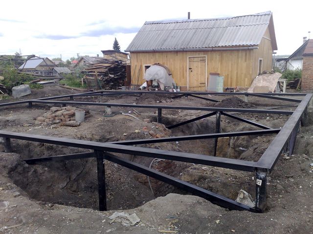
If an armature was inserted into the pipe, it must be released into the channel hole and welded.
When the concrete hardens, the foundation should be loaded so that it settles. To do this, all the material is evenly folded onto it. The process of foundation shrinkage can last one to two months. Now you can proceed directly to the construction of the building. However, it is recommended to start this stage after at least a month has passed since the concrete was poured.
The pipes of the metal foundation are sewn up with asbestos-cement slabs. It is advised to make several "doors" in them so that in spring they can be easily ventilated, avoiding dampness.
An example of collecting loads on a foundation
Initial data:
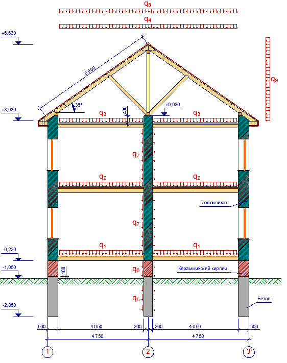
It is planned to build a residential 2-storey building with a cold attic and a gable roof. The roof is supported on two outer walls and one wall under the ridge. No basement is provided.
Construction site - Nizhny Novgorod region.
Terrain type - urban-type settlement.
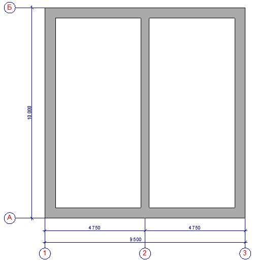
The dimensions of the house are 9.5x10 m along the outer edges of the foundation.
The angle of inclination of the roof is 35 °.
The height of the building is 9.93 m.
The foundation is a reinforced concrete monolithic tape 500 and 400 mm wide and 1 900 mm high.
The base is a ceramic brick, 500 and 400 mm thick and 730 mm high.
External walls - gas silicate with a density of 500 kg / m3, a wall thickness of 500 mm and a height of 6 850 mm.
Internal load-bearing walls - gas silicate with a density of 500 kg / m3, a wall thickness of 400 m and a height of 6 850 mm.
The ceilings and the roof are wooden.
Structures that could trap snow on the roof are not provided.
Foundation plan.
Sectional view of the house, with actual loads.
Required:
Collect loads on the central foundation strip, located under the inner load-bearing wall, if the load area from the floor is 4.05 m2, and from the roof - 5.9 m2.
Collecting loads on an internal load-bearing wall.
We determine the loads acting on 1 m2 of the cargo area (kg / m2) of all structures, the load of which is transferred to the foundation.
| Load type | Norm. | Coef. | Calc. |
| Floor load of the 1st floor (q1) | |||
|
Constant loads: - bottom sheathing made of boards t = 30mm (spruce ρ = 450kg / m3) - insulation t = 180mm (foam plastic ρ = 20kg / m3) - floor boards t = 36mm (spruce ρ = 450kg / m3) Temporary loads: - Living spaces |
13.5 kg / m2 3.6 kg / m2 16.2 kg / m2 150 kg / m2 |
1,1 1,3 1,1 1,3 |
15.4 kg / m2 4.7 kg / m2 17.8 kg / m2 195 kg / m2 |
| TOTAL | 183.8 kg / m2 | 232.9 kg / m2 | |
| Floor load of the 1st floor (q2) | |||
|
Constant loads: - bottom sheathing of boards t = 16mm (spruce ρ = 450kg / m3) - floor boards t = 36mm (spruce ρ = 450kg / m3) Temporary loads: - Living spaces |
7.2 kg / m2 16.2 kg / m2 150 kg / m2 |
1,1 1,1 1,3 |
7.9 kg / m2 17.8 kg / m2 195 kg / m2 |
| TOTAL | 173.4 kg / m2 | 220.7 kg / m2 | |
| Floor load on the 2nd floor (q3) | |||
|
Constant loads: - bottom sheathing made of boards t = 30mm (spruce ρ = 450kg / m3) - insulation t = 180mm (foam plastic ρ = 20kg / m3) - top sheathing made of boards t = 30mm (spruce ρ = 450kg / m3) Temporary loads: - attics |
13.5 kg / m2 3.6 kg / m2 13.5 kg / m2 70 kg / m2 |
1,1 1,3 1,1 1,3 |
15.4 kg / m2 4.7 kg / m2 15.4 kg / m2 91 kg / m2 |
| TOTAL | 100.6 kg / m2 | 126.5 kg / m2 | |
| Load from roof structures (q4) | |||
|
Constant loads: - inner lining of boards t = 16mm (spruce ρ = 450 kg / m3) - rafters (spruce ρ = 450kg / m3) - lathing (spruce ρ = 450kg / m3) - flexible shingles (ρ = 1 400kg / m3) Temporary loads: - roof maintenance |
7.2 kg / m2 3.4 kg / m2 3.3 kg / m2 7 kg / m2 100 kg / m2 |
1,1 1,1 1,1 1,3 1,3 |
7.9 kg / m2 3.7 kg / m2 3.6 kg / m2 9.1 kg / m2 130 kg / m2 |
| TOTAL | 120.9 kg / m2 | 154.3 kg / m2 | |
| Foundation weight (q5) | |||
|
Constant loads: - weight of reinforced concrete tape 400 mm wide (reinforced concrete ρ = 2 500 kg / m3) |
1,000 kg / m2 |
1,1 |
1 100 kg / m2 |
| TOTAL | 1,000 kg / m2 | 1 100 kg / m2 | |
| Ceramic brick weight (q6) | |||
|
Constant loads: - weight of ceramic bricks 400mm (ρ = 1600 kg / m3) |
640 kg / m2 |
1,1 |
704 kg / m2 |
| TOTAL | 640 kg / m2 | 704 kg / m2 | |
| All gas silica blocks (q7) | |||
|
Constant loads: - weight of gas silicate 400mm (ρ = 500 kg / m3) |
200 kg / m2 |
1,1 |
220 kg / m2 |
| TOTAL | 200 kg / m2 | 220 kg / m2 | |
| Snow (q8) | |||
|
Temporary loads: - snow |
140 kg / m2 |
1,4 |
196 kg / m2 |
| TOTAL | 140 kg / m2 | 196 kg / m2 | |
| Wind (q9) | |||
|
Temporary loads: - wind |
15 kg / m2 |
1,4 |
21 kg / m2 |
| TOTAL | 15 kg / m2 | 21 kg / m2 |
We determine the standard and design load on the foundation:
qnorms = 183.8kg / m2 4.05m + 173.4kg / m2 4.05m + 100.6kg / m2 4.05m + 120.9kg / m2 5.9m + 1000kg / m2 1.9m + 640kg / m2 0.73m + 200kg / m2 6.85m + 140kg / m2 5.9m + 15kg / m2 2.95m = 7174.85 kg / m2.
qsettlement = 232.9kg / m2 4.05m + 220.7kg / m2 4.05m + 126.5kg / m2 4.05m + 154.3kg / m2 5.9m + 1100kg / m2 1.9m + 704kg / m2 0.73m + 220kg / m2 6.85m + 196kg / m2 5.9m + 21kg / m2 2.95m = 8589.05 kg / m2.
The need for and its conditions
Calculation is necessary to identify the generated load per 1 sq. M. soil in accordance with the permissible indicators.
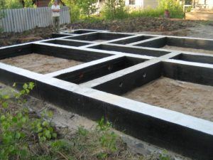 Competent collection of loads is a guarantee of foundation reliability
Successful implementation of the above measure provides for the necessary consideration of the following parameters:
- climate conditions;
- soil type and its features;
- groundwater boundaries;
- design features of the building and the amount of material used;
- the layout of the structure and the type of roofing system.
Taking into account all the listed characteristics, the calculation of the foundation and the verification of compliance are carried out after the approval of the construction project.
Calculation of an eccentrically compressed column.
Here, of course, the question arises: how to calculate the rest of the columns, because the load will most likely be applied to them not in the center of the section? The answer to this question strongly depends on the way the canopy is attached to the columns. If the canopy beams are rigidly attached to the columns, then a rather complex statically indefinable frame will be formed, and then the columns should be considered as part of this frame and the cross-section of the columns should be calculated additionally for the action of the transverse bending moment, but we will further consider the situation when the columns shown in the figure 1, are pivotally connected to the canopy (we no longer consider the column marked in red).For example, the head of the columns has a support platform - a metal plate with holes for bolting the canopy beams. For various reasons, the load on such columns can be transmitted with a sufficiently large eccentricity:
Figure 2. Eccentricity of a concentrated load applied to a column due to canopy beam deflection.
The beam, shown in Figure 2, in beige, will bend a little under the influence of the load (why this will happen is discussed separately) and this will lead to the fact that the load on the column will be transmitted not along the center of gravity of the column section, but with eccentricity e and when calculating the extreme columns, this eccentricity must be taken into account. A more accurate definition of eccentricities depends on the stiffness of the column and beam, but in this case we will not take into account the stiffness and for reliability we will take the most unfavorable value of the eccentricity. There are a great many cases of eccentric loading of columns and possible cross-sections of columns, described by appropriate formulas for calculation. In our case, to check the cross-section of an eccentrically compressed column, we will use one of the simplest:
(N / φF) + (Mz/ Wz) ≤ Ry (3.1)
Those. it is assumed that eccentric loading is present only about one axis.
In this case, when we have already determined the section of the most loaded column, it is enough for us to check whether such a section is suitable for the remaining columns, for the reason that we do not have the task of building a steel plant, but we simply calculate the columns for the shed, which will all be of the same section for reasons of unification.
What are N, φ and Ry we already know.
Formula (3.1) after the simplest transformations will take the following form:
F = (N / Ry) (1 / φ + ezF / Wz) (3.2)
since the maximum possible value of the bending moment Mz = N ezwhy the value of the moment is exactly the same and what is the moment of resistance W is explained in sufficient detail in a separate article.
The concentrated load N on the columns marked in blue and green in Figure 1 will be 1500 kg. We check the required cross-section with such a load and a previously determined φ = 0.425
F = (1500/2050) (1 / 0.425 + 2.5 3.74 / 5.66) = 0.7317 (2.353 + 1.652) = 2.93 cm2
In addition, formula (3.2) allows you to determine the maximum eccentricity that the already calculated column will withstand, in this case the maximum eccentricity will be 4.17 cm.
The required section of 2.93 cm2 is less than the accepted 3.74 cm2, and therefore a square shaped pipe with a cross-sectional size of 50x50 mm and a wall thickness of 2 mm can also be used for the outer columns.
Note: Actually, the bending moment from the eccentricity in the most dangerous section, located approximately in the middle of the column height, will be 2 times less, respectively, and the required section area will also be slightly less. But as I already said, when performing a calculation by a non-specialist, an additional margin of safety will never hurt. In addition, in this case, we still take a large cross-sectional area for structural and aesthetic reasons.
Installation of metal columns
Installation of a metal support
Metal columns are mounted on bases, in which anchor bolts are inserted in advance to secure them. After design, the standard position of the supports is ensured by the exact placement of the anchor bolts in the fixing points. At the same time, the accuracy of the installation is ensured by serious preparation of the base plane.
The support of the columns is done as follows:
- On the surface of the base, which is mounted to the desired level of the support sole, without further adding the cement mixture. It is used for supports with milled shoe soles.
- At pre-verified places, metal plates are installed and filled with a concrete mixture. The base is concreted to a level of 5-8 cm below the level of the support sole, which was indicated during the design.
- After that, the support columns are installed, combining the axial marks of the alignment axes on the elements mounted in the foundation, with their marks. The set screws adjust the position of the individual support in height, taking into account the fact that the top surface of the plate will be located at the specified elevation of the support plane of the shoe. The supporting planes of the pillars must be planed in advance.
- The base is concreted to a level 0.25-0.3 m below the shoe surface mark, marked during its design.
After completing these works, the embedded elements and components of the supports are mounted. The upper part of the base is cemented to a level 4-5 cm below the upper plane of the supporting elements. The support surface of the shoe is made at right angles to the axis of the post itself.
Bookmark scheme
Let's try to figure out how to reinforce a columnar foundation with our own hands. Suppose that we have determined the size and amount of material, have prepared everything necessary for work.
We install four corrugated rods with a diameter of 1 cm in each pit under the support post. If you have to pour supports with a circular cross-section, it is recommended to use six eight-millimeter rods.
The support sole for each pillar is reinforced with a welded mesh made of reinforcement with a cross section of 6 - 8 mm, laid in two rows, while the thickness of the edge of the sole should be at least fifteen centimeters.
In some cases, if supporting elements with a variable cross-section are poured in the form of steps, the reinforcement is performed by two or more frames connected into a single structure with a knitting wire.
The mushroom pillars are double reinforced. The first layer of metal rods is bent in the form of separate elements in the shape of "L", while the vertical part is equal to the height of the support, and the curved side is trimmed to the size of the diameter.
The elements placed in the prepared well are corrected in such a way that their horizontal parts diverge radially from the central point to the periphery of the pillar base.
After that, a conventional frame blank is mounted in the well, and concreting is performed. The result is a pillar that is strong enough and resistant to extrusion.
According to a similar scheme, a frame made of reinforcement is mounted when installing a grillage. In the future reinforced concrete beam, reinforcing bars with a cross section of 1 cm are laid in two or three pieces. On the corner sections of the foundation, the rods are bent by at least twenty centimeters, connections are made by welding or knitting wire. In the same way, the grillage frame base is connected to the rods of the support pillars, and after that, you can start feeding the concrete mixture.
