Methods for calculating the bearing capacity for various parameters
The bearing capacity of a pile depends on a number of parameters. The main ones are the material of the support and the types of soil with which it contacts during deepening. Based on these characteristics, you can easily calculate the required number of elements of the pile foundation and their geometric parameters.
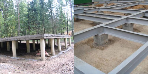
Among the most widespread in private housing construction, the following pile foundations can be distinguished:
- On screw piles;
- On driven supports;
- With the help of bored piles.
Each option is good in certain cases and can be used in the construction of buildings of various designs and number of storeys.
Calculation of the foundation on screw piles
Screw piles are steel tubular supports equipped with blades at the bottom to facilitate the process of penetration into the ground. For the construction of houses, elements with a diameter of 133, 108 and 89 mm are used. Thinner piles can be used for the installation of lightweight structures such as gazebos and terraces.
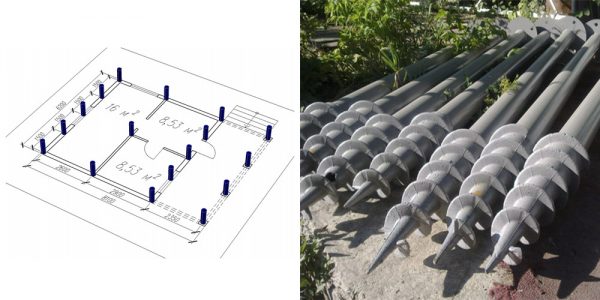
Foundation on screw piles
The bearing capacity of a pile with blades depends on the following support parameters:
- Pipe diameter;
- The length of the pipe immersed in the soil;
- The diameter of the vanes that distribute the final load on the ground.
Even pipes of the largest diameter do not allow them to be used for structures made of relatively heavy building materials such as bricks and concrete wall blocks. To match the load of the house, even on such powerful soils as clay, the pitch of screw piles can be 0.3 meters, which is unprofitable from the point of view of technology and construction economics.
Features of the foundation on driven piles
The maximum possible bearing capacity of a driven pile allows widespread use of this type of foundations, even in the construction of multi-storey residential buildings. This contributes to their distribution during the construction of structures up to 40-60 meters high.
The use of specialized construction equipment allows the use of supports, the length of the lateral surface of which can be tens of meters. The hammered pile with its lower end rests on high-strength rocks, transferring to them the load from the structure of the house. The strength of the support material is sufficient to maintain its integrity under such a high load.
In private housing construction, the foundation on driven piles is very poorly distributed. This is due to the high cost of renting pneumatic driving equipment and its operators. Only in extreme cases, construction engineers are inclined in favor of this type of foundation for two-story private houses.
Bored piles - the best foundation option
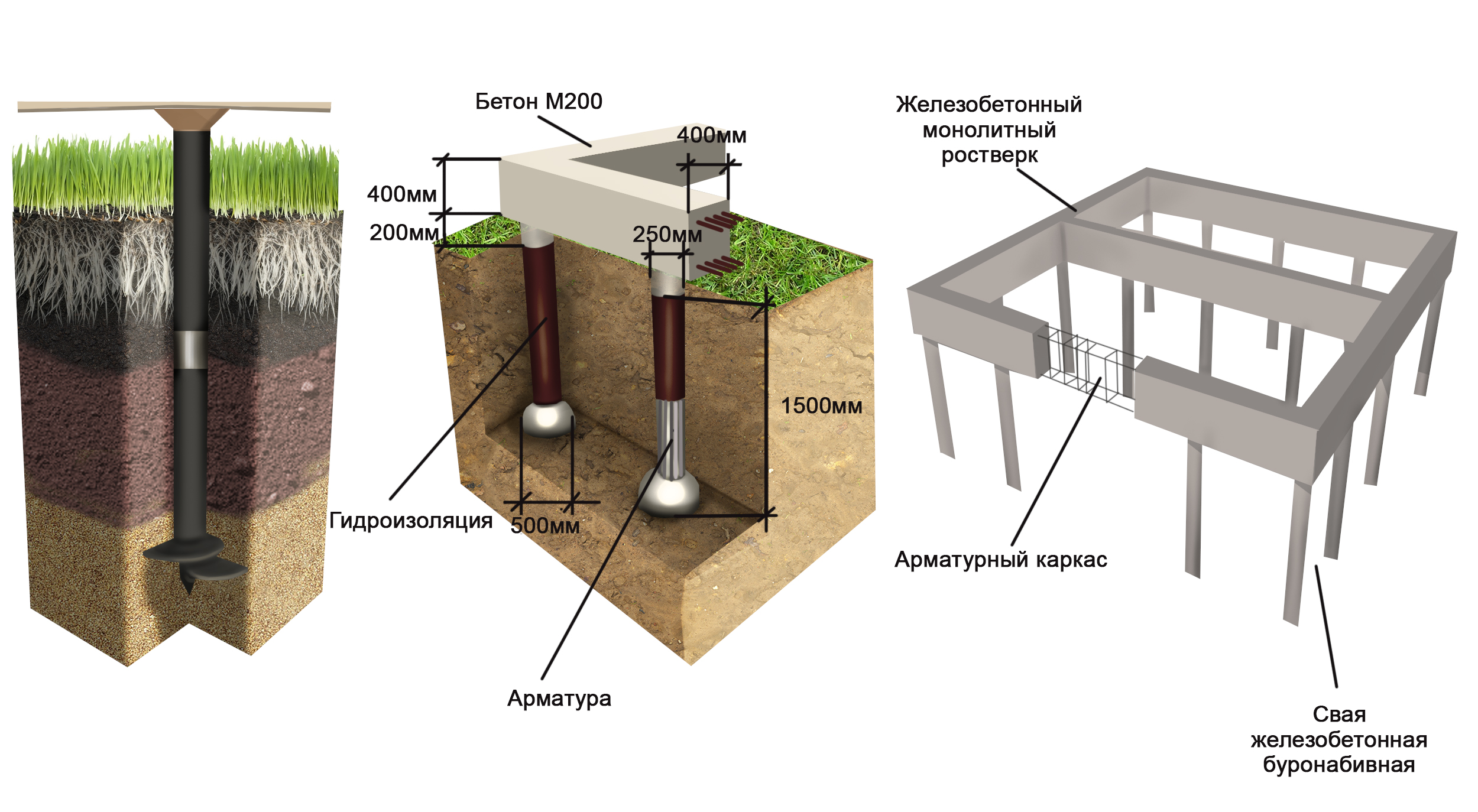
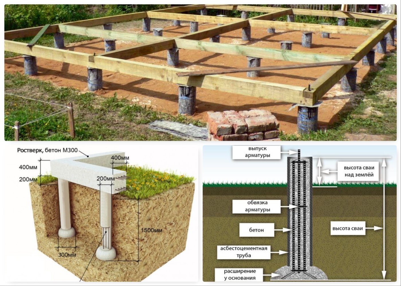
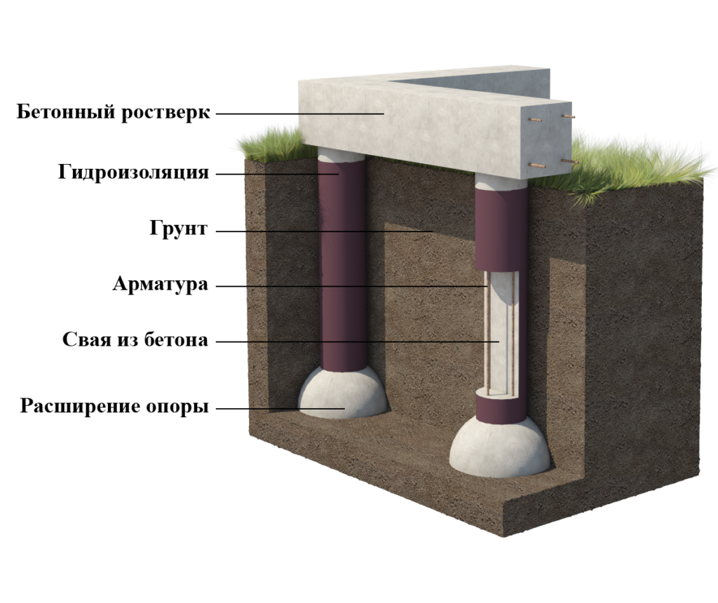
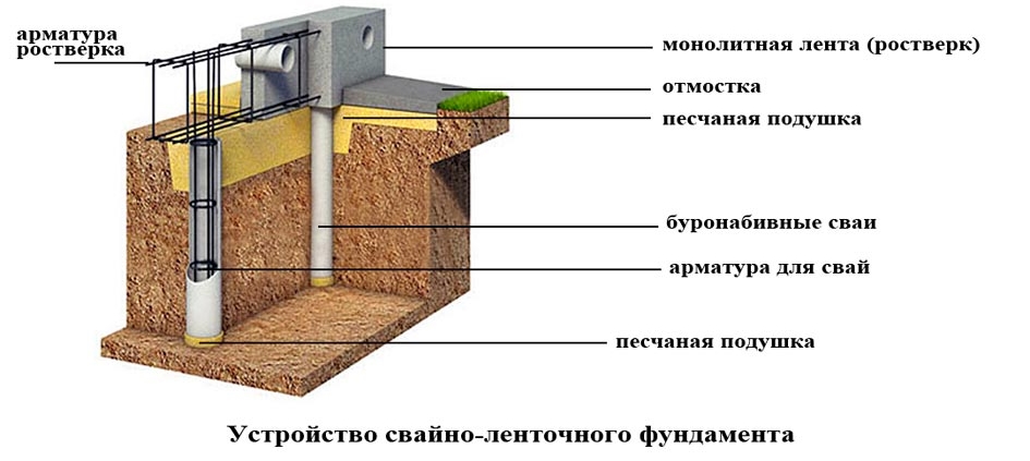
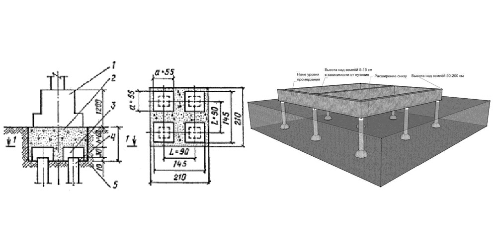
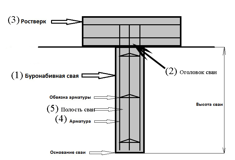
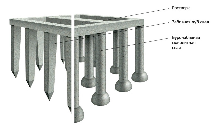
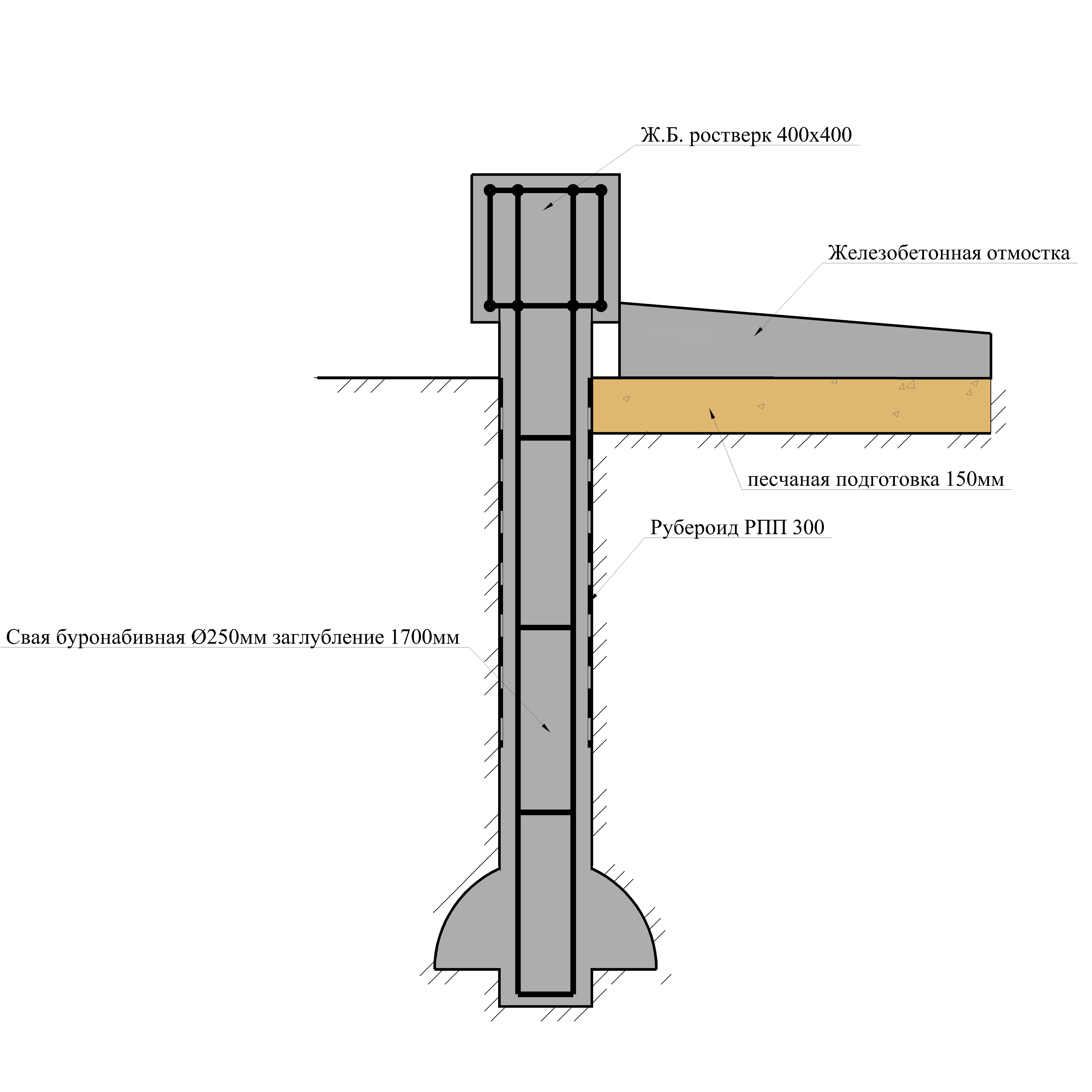
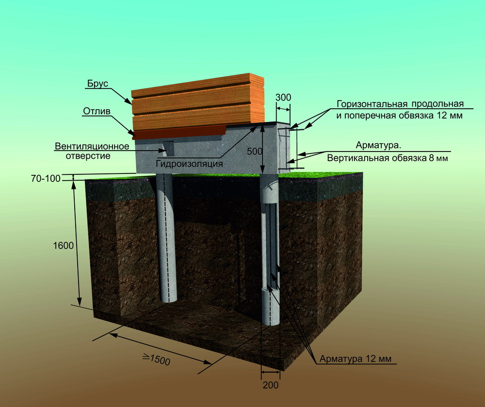
Bored piles are similar to driven piles, but the installation of the support body is carried out directly at the construction site. For this, a hole is drilled in the ground, into which a hollow cylindrical formwork in the form of pipes is lowered. A steel reinforcing frame is installed inside and the cavity is filled with concrete. To increase the bearing capacity of the pile, it is possible to manufacture its lower end in the form of a hemispherical or conical expansion.
An important aspect is the material from which the support is made and the method of its manufacture. The maximum value is typical for reinforced concrete factory racks. The bearing capacity of the pile in terms of material in the calculations is characterized by coefficients, the value of which is determined according to the corresponding tables.

Foundation on bored piles
In the process of drilling the first or test hole at the construction site, it is necessary to study the existing soil layers as carefully as possible, because each type of soil has a different bearing capacity of the pile. Specific figures for each type of soil can be easily found in the corresponding GOST, which is called “Soils.Classification". These values are taken into account when determining the bearing capacity of the pile on the ground.
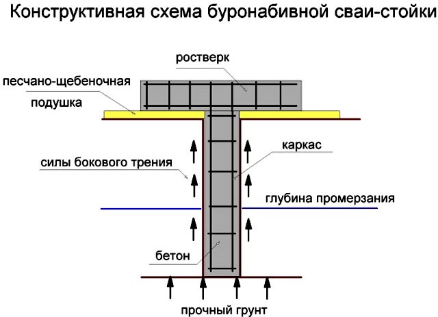
A bored pile, like a driven pile, due to its tight fit into the soil, transfers the load from the structure of the house not only with its lower end, but also along the entire lateral surface. This distinguishes them from pile supports and serves as an undeniable advantage. For a more thorough study of the technology for calculating the bearing capacity of a pile, let us consider it with a specific example.
How to create a bored pile structure with your own hands?
After all the wells have been drilled, the developer can start pouring the bored piles with his own hands. This process requires adherence to technologies that provide for the phased implementation of all work. The developer in this matter will be helped by step-by-step instructions, thanks to which they will be able to minimize errors and build reliable and durable supporting structures.
A do-it-yourself bored foundation is created as follows:
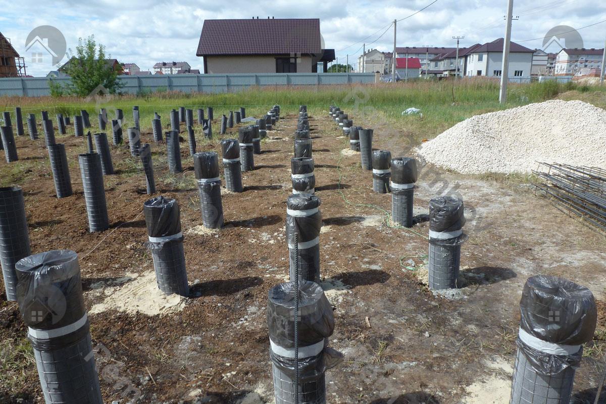
- Formwork is being built, the type of which is determined based on what technology will be used for the piles. If the borehole diameter does not exceed 50 cm, then a piece of roofing material can be used, which rolls up in the form of a cylinder and is immersed in the hole. When erecting cottages and light buildings, a polymer pipe can be used for formwork. For more massive structures, an asbestos-cement pipe should be used, which will improve the bearing capacity of the foundation structure. If the wells have a large diameter, then the developer will have to use panel formwork, which is usually used when pouring a columnar foundation.
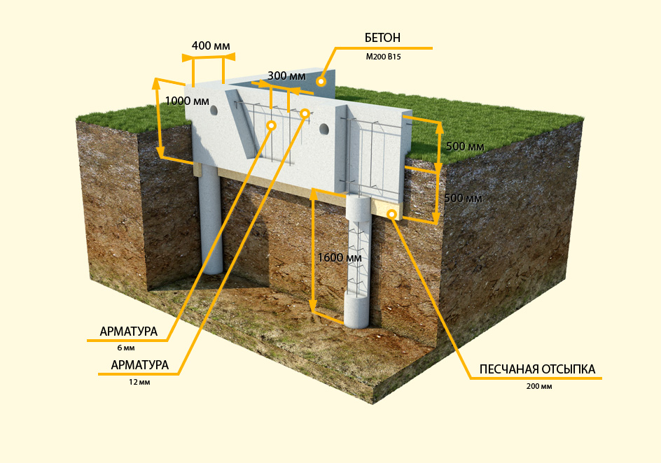
- Formwork reinforcement. The use of metal frames when creating bored piles allows them to provide maximum strength, reliability and durability. To create a frame, developers will have to use 4 rods (vertical), the diameter of which must exceed 10 mm. A metal ring is installed between the reinforcement in several places, which will fix the diameter of the frame. Strapping is carried out on top of such a structure. The self-made reinforcing cage is installed in the well so that the upper rods protrude from the concrete. This is necessary in order to subsequently perform a bundle of piles with a grillage.
- When pouring bored piles, the technology provides for the use of concrete, the grade of which starts at B22.5. A hopper should be installed at the wellhead to prevent soil collapse, which will create an uneven concrete structure. Through it, the concrete mixture will be fed into the hole, which contains formwork and a reinforced structure. If the developer will use a coarse-grained filler for concrete, then he should use a deep vibrator nozzle during the pouring process. The technology for creating bored piles prohibits the use of brick broken as a filler for concrete mix.
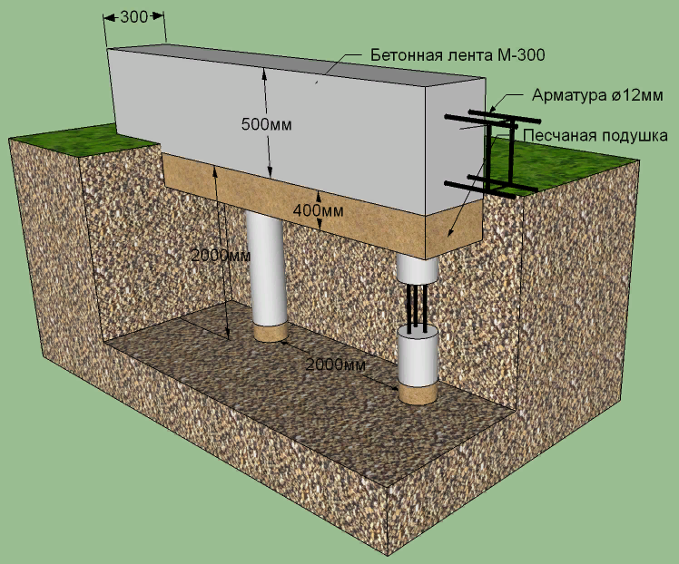
- The creation of the grillage is the final stage in the construction of the bored foundation structure. The developer must build formwork around the entire perimeter of the foundation. The shields are fixed to each other with studs, and reinforcement is laid inside. A grillage for this type of foundation cannot pass engineering communications, so they are carried out under it.
After the completion of the concreting, the formwork is dismantled. Sand is removed from under the grillage, and the resulting voids are protected from accidental filling with soil with sheet material. Self-creation of such a foundation structure will allow the developer to save up to 40% of their budget.
6.2 Construction of bored piles and materials
6.2.1 The depth of the foundation of reinforced concrete
vibro-stamped bored piles are assigned based on hydrogeological
conditions, design solutions for the underground part of structures and the availability
communications.When choosing a supporting soil layer, it should be borne in mind that when
vibrating ramming of crushed stone into the bottom of the wells in the ground below the bottom mark
a crushed stone "core" is formed, in shape close to a cone with a height of at least
borehole diameter with a zone of compacted soil around the "core". For
vibrating ramming should use hard rock crushed stone (granite,
gravel, etc.) with a grain size of 20 - 40 mm (or 40 - 70 mm) according to GOST
8267-93.
6.2.2 Piles must be reinforced in advance
manufactured frames of projected length. It is allowed to build up the frame up to
design length by joining, in accordance with the requirements of the working
documentation, directly when lowering it into the drilled well.
6.2.3 Frame design and technology
installation are assigned based on ensuring the design position (centering)
the frame in the well and the size of the concrete cover is at least 70 mm in the clear. WITH
for this purpose, the required amount is installed on the reinforcing cage
spacers of appropriate quality and geometrical parameters.
6.2.4 Design indicators of strength,
frost resistance and water resistance of concrete are ensured by prescribing the optimal composition of the concrete mixture,
which should be selected by the method of laboratory selection based on the specific
properties of the materials used (cement, aggregates, additives) in accordance
with the instructions of Appendix 4 SP 46.13330.2012 and the recommendations of this
methodological document. In this case, the composition of the concrete mixture for concreting
wells with volumetric vibration stamping should be selected based on the possibility
"Revitalization" of the laid concrete mix with vibration equipment for 3 hours in case
forced pauses in the supply of a fresh portion of the mixture (appendix).
6.2.5 Concrete mixture laid in the borehole at
using volumetric vibration stamping, can ensure the acquisition of concrete in
the age of 28 days established by the project quality indicators for strength,
corresponding to a class not lower than B25, water resistance not lower than W6 and frost resistance not lower than F200.
6.2.6 For the preparation of a concrete mixture,
use Portland cements of at least 400 grade with normalized mineralogical
composition (Sec.
1.14 GOST 10178-85),
at C3And no more than 8%,
no additive Portland cements or containing no more than 5% of mineral additives in
in accordance with Appendix 3 of the joint venture
46.13330.2012.
6.2.7 As additives that improve
technological properties of the concrete mixture and improving the quality of concrete, should
apply the additives specified in Appendices 3 and 6 of the SP
46.13330.2012.
6.2.8 As a coarse concrete aggregate
the mixture should be granite crushed stone with a grain size of 5 - 20 mm,
obtained by crushing undisturbed rocks in accordance with
the requirements of GOST 26633-91.
For the preparation of crushed stone, a rock is used that has a water-saturated
condition with strength not less than 80 MPa, with water absorption not more than 0.5%.
6.2.9 For concrete mix it is necessary to use
natural quartz sand or crushed sand from high-strength igneous rocks
with a fineness module of at least 2.5 in accordance with the requirements of GOST 26633-91.
6.2.10 Cement and aggregates should be dosed according to
mass, and aqueous solutions of plasticizing and air-entraining additives - by
volume.
6.2.11 Indicators of concrete mix at the place of placement
assigned by the Technological Regulations depending on the filling method
wells.
Useful Tips
The pile-grillage foundation must be erected correctly, adhering to all construction technologies - this will help to increase its technical and operational characteristics.
If construction work is carried out by novice craftsmen, then they need to take into account some of the recommendations of experienced specialists.
- The installation should start with calculations. For this, the type of soil and the depth of the grillage are determined.If the support depth is insufficient, the building can shrink and crack, and then even collapse.
- A huge role is played by the study of the soil, on which the bearing capacity of the structure depends. The highest indicators are found in rocks and stony soils. If the composition of the soil is determined incorrectly, this will lead to errors in the calculations of the load of the structure, as a result of which it will sink into the ground.
- There must be a good connection between the piles and the grillage, since the unstable structure can collapse under the influence of soil pressure.
- Regardless of the type of foundation, it is imperative to lay a sand cushion at the depth of freezing - this is especially true for the operation of the foundation in winter. Frozen ground can expand and cause the grillage to break.
- The grillage should not touch the surface of the ground or be buried in it. It is necessary to remove a small layer of soil around the entire perimeter of the site, then install the formwork, fill in the sand and pour concrete.
- The step between the piles should be accurately calculated. This indicator is determined in accordance with the load on the foundation, the diameter and the number of reinforcement.
- During the reinforcement, it is worthwhile to provide for the required amount of ventilation ducts. All internal compartments must be connected to outside exits.
- Insulation and waterproofing play a huge role in the construction of the base. They should be laid before the foundation is poured with concrete.
- The bottom of the pit or trench must be tamped down and not loosened. It should not be allowed that earth from the walls crumbled onto the base. In addition, sedimentary water must flow away from the trench or foundation pit, otherwise the bottom will get wet and be unsuitable for filling with a solution. Excessive slope steepness is also unacceptable in trenches.
- Weak soil requires reinforcement with piles and good backfill.
- The sand that is used to fill the air cushion must be moistened and the cushion must be distributed under the contour to the edge at an angle of 45 degrees.
- The formwork must be securely fastened, since when poured with concrete, it may not withstand the load and collapse. The deviation of the formwork from the vertical by more than 5 mm is not allowed.
- The height of the foundation is made with a small margin of 5-7 cm from the height indicated in the project.
- When reinforcing the frame, it is recommended to use rods with a total cross-sectional area of at least 0.1% of the area of the concrete element. In this case, it is best to choose smooth fittings that do not have traces of rust, dirt and paint.
- It is undesirable to fasten the reinforcement by welding - this can violate its strength at the joints.
- The grade of concrete for pouring should be chosen depending on the construction of the base and the climatic conditions of the region.
For information on the design features of the pile-grillage foundation, see the following video:
General instructions
4.1.
When installing bored and pipe-concrete piles in permafrost
the requirements of the chapters of SNiP should be observed: according to the rules of production and acceptance
works of foundations and foundations, according to the rules of production and acceptance of works
concrete and reinforced concrete monolithic structures, safety regulations on
construction, SI 393-69 "Instructions for welding joints of reinforcement and
custom details of reinforced concrete structures ", as well as the requirements
of this section.
4.2. TO
the production of work on the installation of bored and pipe-concrete piles is allowed
only persons who have undergone special training in knowledge of the requirements of this
Instructions.
4.3.
The projects for the production of work should provide for:
a)
supply of drilling rigs with hot water in winter;
b)
drill cuttings discharge points;
v)
areas for storing sections of reinforcement cages and casing pipes in a radius
actions of cranes;
G)
holding of concrete piles in permafrost soil by the "thermos" method and
electric heating of concrete to a depth of 5 m at negative air temperatures;
e)
installation in every fourth pile for the entire depth of the well of a steel tube
with a diameter of 38-50 mm to control the temperature regime of concrete
by the "thermos" method. Installation of the same 5 m long tubes in all
the rest of the piles during concreting during the period of the year with negative air temperatures
to control the temperature regime of concrete electric heating. Tubes in both
cases should be installed in the zone of contact of concrete with the soil of the walls of wells
or concrete with casing pipes;
e)
device of special wells or equipped room for holding
control concrete samples at the temperature of permafrost.
4.4. Before
to start drilling wells:
a)
preliminary layout of the construction site according to the project;
b)
device of car entrances;
v)
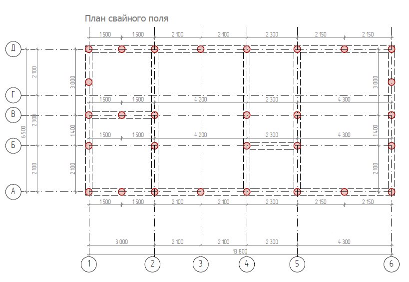
breakdown and fixing on the site of the main axes of the pile field;
G)
work in accordance with the requirements specified in "a", "b" and "c" of this Instruction.
4.5. V
the pile installation process should keep a log of pile work in the form,
specified in this Instruction. The journal must be filled on a day
performance of work on each pile separately.
4.6. Cranes for all lifting operations
when installing piles, they must have a lifting capacity, lifting height and outreach
booms providing the installation of vertically moving pipes (in the case of
concreting using the "VPT" method), installation of sections of reinforcing cages and
supply of containers (buckets) with concrete mixture to pile wells.
Peculiarities
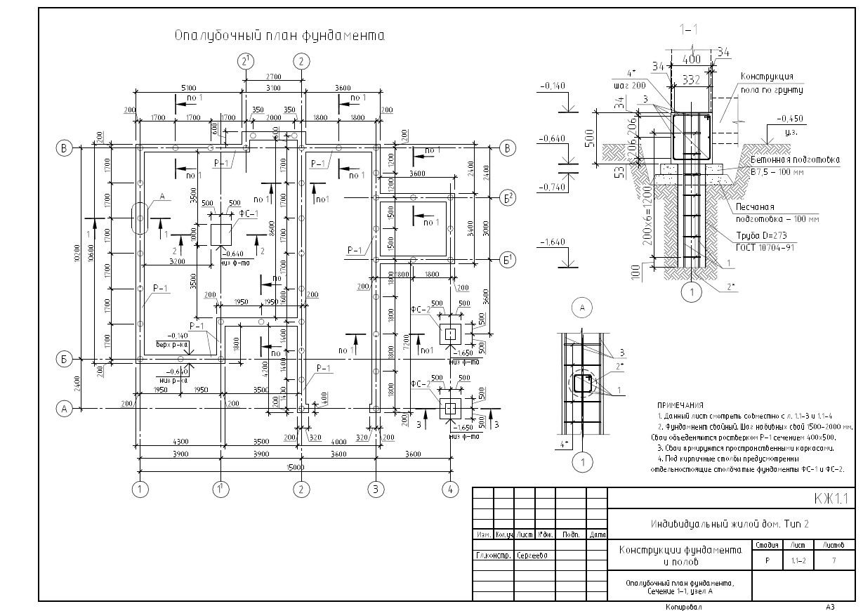
The technology provides for the presence of free-standing supports and a connecting element - a grillage. The pile depth depends on the geological conditions on the site and the structural features of the building. Drilling wells over a long distance allows you to increase the contact area of the building support with the ground. This increases the friction. Such foundations are capable of withstanding heavy loads.
Device diagram
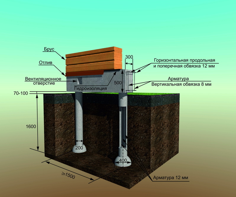
The device of bored piles has one serious drawback: all supports work separately. This option increases the likelihood of uneven precipitation, which is dangerous for almost all types of buildings. To prevent the destruction of the walls, a reinforced concrete tape grillage is provided. Its reinforcement allows it to take bending loads well and unite all the supports into one foundation. The manufacturing technology of the grillage can be different depending on the geological conditions.
Bored piles - what is it
The technology of bored pile installation includes two processes: drilling wells and filling them with reinforced concrete right at the work site. That is, vibrations that inevitably arise when the finished piles are driven by the shock or vibration method are excluded. Because of these vibrations, blocking in the city is practically not used, and the vibration method is limited.
In terms of safety, screw piles can compete with bored ones. But they are only suitable for low-rise buildings due to their limited bearing capacity. A bored foundation may well take on the load from a multi-storey building, it all depends on the parameters of the piles and grillage. In particular, the immersion depth of a concrete rod can be up to 30 meters or even more.
Other advantages of bored pile technology:
- the possibility of using on soils with debris. In this case, the immersion of finished piles is complicated by natural obstacles and it is practically impossible without drilling leader wells;
- compactness of equipment. Thanks to her, bored piles can be made even underground;
- relative cheapness of the process - cheap consumables and no expensive heavy equipment is required.
The design of piles and the foundation as a whole is carried out on the basis of design parameters:
- immersion depth;
- trunk section;
- the number of piles and the distance between them.
This also includes the presence / absence of broadening. Broadening (heel) is mandatory on clay soils to avoid pushing the pile out during frost heaving. In other cases, it depends on the characteristics of the soil and structure. Our specialist will provide advice on this and other issues for your object free of charge.
The pile parameters are determined based on the expected loads on the foundation. The following loads are taken into account:
- the mass of the structure;
- soil resistance at the foot of the pile;
- soil resistance at the lateral surface of the concrete rod.
The initial data for different soils, the necessary coefficients are in the SNiP tables. Key technical and organizational aspects of the workflow are presented in the technological map for bored piles:
- introductory part - scope;
- justification of the choice of technology, its features for a given object;
- recommendations for the organization of work;
- production cycle schedule for this type of wells;
- calculation of labor costs;
- technical and economic indicators, time spent on equipment operation;
- a list of resources - equipment, tools, materials with an indication of GOST for each position;
- quality control chart indicating the position of the person responsible for controlling each operation.
We have been assembling bored piles for over 10 years
For all questions call: 8 800 707-72-09
We will help you choose the most suitable and economical option for manufacturing a bored foundation.
Drilling technology with wellbore protection
The drilling technology is also used to protect the walls of wells from collapse by filling it with a special clay solution, the wellhead is strengthened with a short casing;
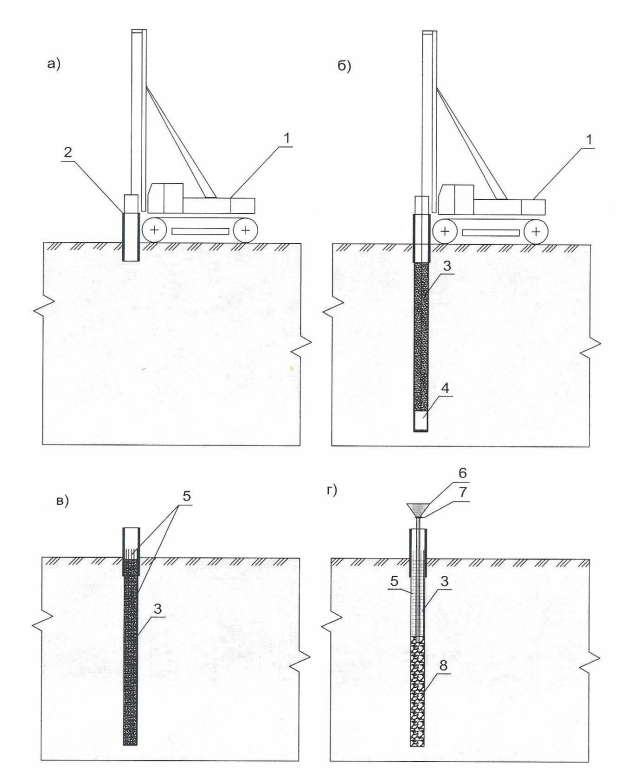
Technology of construction of bored piles with drilling of wells under
- a) - stage 1 - casing of the wellhead;
- b - stage 2 - soil extraction under the protection of a clay solution;
- c - stage 3 - installation of a reinforcing cage in the well;
- d - 4th stage - concreting of the well using the HMW method.
- drilling rig;
- short casing;
- clay solution;
- working body of the drilling rig;
- reinforcement cage;
- concrete pipe with funnel;
- damper;
- concrete pillar
- the wellhead is reinforced with a short casing;
- soil is extracted from the well under the protection of bentonite mud;
- a reinforcing cage is installed in the well;
- the well is concreted using the vertically moving pipe (VTP) method.
Drilling of the wells piles protected Inventory casing pipes are most often used for bridge foundations.
For fixing the walls of the wells, inventory steel casing pipes with a diameter of 1.2 are used; 1.5; 1.7; 2.0 m. They consist of intermediate sections with lengths of 2, 4 and 6 m, butted by threaded conical plugs, and a knife section with a cutting crown with teeth.
When using this technology, preparatory work is first carried out:
- cutting by a bulldozer with loading into dump trucks with the help of loaders and storage in a designated place of the vegetation layer of the soil, layout of the working platform and device
entrances; - splitting and fixing the axes of the support and each pile on the basis of a geodetic alignment base;
- delivery and assembly of drilling, crane and concrete casting equipment;
- preparation of a site made of reinforced concrete slabs for a drilling machine and other equipment, installation of an inventory base plate for a drilling table.
After completing all the preparatory work, wells are drilled in the following order:
| № | Work order |
| 1 | after installing the drilling machine in a working position, using a boom crane, the lower part of the casing with a knife section is installed, the subsequent sections are combined with conical threaded plugs (the total length of the casing is assigned from the condition of raising it above the level of the working platform by 1.5 m for placement crimp clamp); |
| 2 | casing pipes are immersed with jacks in the ground with rotary-pressing movements to the design depth; |
| 3 | remove soil from the cavity of the casing pipe in various ways: in sandy, clayey soils of plastic, semi-solid and solid consistency, a percussion grab or auger method of drilling is used; in water-saturated sands, quicksands and silts, the soil is developed with a thief with a check valve and translational movements of the casing); |
| 4 | the soil extracted from the well is stored in special containers and then taken out to pre-designated places, the soil from the wells of the foundations of the channel supports is loaded onto the pontoons from the inventory pontoons of the KS |
| 5 | as necessary, the casing pipe is built up in successive sections using a jib crane, all sections are cleaned of dirt in advance (a section for cleaning and washing the casing pipes is organized at the construction site) |
| 6 | drilling is carried out to the full depth, for control, after installing the rig at the drilling site, on its mast, about 1 m from the surface of the earth (working bridge), a line of conditional zero is applied, from which the count is taken |
| 7 | when developing unstable soils in a well, support the water level is 1 ... 1.5 m above the water level in the river for preventing the influx of water and soil into the well |
| 8 | after reaching the design mark before installing the arma- the bottom hole is thoroughly cleaned from drill cuttings |
| 9 | during drilling operations, they constantly monitor the characteristics of the traversed soils, to control the compliance with the design geology and identify the need to replace the working body, drilling data are entered into the well drilling log; before each installation of a new section of the casing, as well as when the characteristics of the soil change, the depth of the well is measured with a lot and the bottom mark is determined; |
| 10 | in the process of drilling, the position of the casing knife is constantly monitored relative to the level of the developed soil |

Extension of the casing pipe with a truck crane
At the end of drilling, the depth of the well and the quality of clean-up of the borehole bottom are monitored by slowly lowering the working body and a test sampling of drill cuttings from the bottom of the borehole.
Appendix 1. Examples of reinforcement of bored reinforced concrete piles

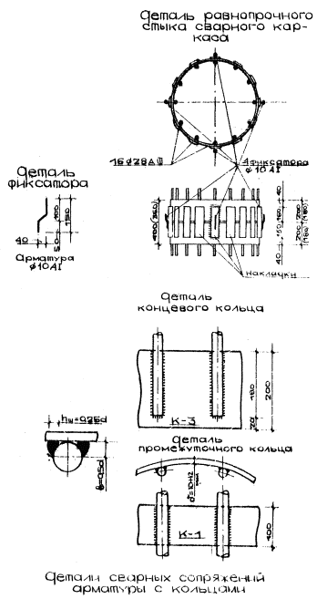
Specification
reinforcing steel per grade
|
The elements |
Brand |
||||||||||||||
|
d-920 / 28-16 |
d-820 / 28-16 |
d-720 / 28-16 |
|||||||||||||
|
Dn×δ1, |
ℓ, |
n, |
nℓ, |
total |
Dn×δ1, |
ℓ, |
n, |
nℓ, |
total |
Dn×δ1, |
ℓ, |
n, |
nℓ, |
total |
|
|
Longitudinal |
28AIII |
8000 |
16 |
128 |
617 |
28AIII |
8000 |
16 |
128 |
617 |
28AIII |
8000 |
16 |
128 |
617 |
|
Spiral |
10AI |
95500 |
3 |
287 |
177 |
10AI |
85000 |
3 |
255 |
157 |
10AI |
74500 |
3 |
224 |
138 |
|
End |
920×12 |
200 |
2 |
0,4 |
107 |
820×12 |
200 |
2 |
0,4 |
96 |
720×12 |
200 |
2 |
0,4 |
83 |
|
Intermediate |
920×10 |
100 |
2 |
0,2 |
45 |
820×10 |
100 |
2 |
0,2 |
40 |
720×10 |
100 |
2 |
0,2 |
35 |
|
Total weight |
946 |
909 |
873 |
|
The elements |
Brand |
||||||||||||||
|
d-920 / 25-16 |
d-820 / 25-16 |
d-720 / 25-16 |
|||||||||||||
|
Dn×δ1, |
ℓ, |
n, |
nℓ, |
total |
Dn×δ1, |
ℓ, |
n, |
nℓ, |
total |
Dn×δ1, |
ℓ, |
n, |
nℓ, |
total |
|
|
Longitudinal |
25AIII |
8000 |
16 |
128 |
493 |
25AIII |
8000 |
16 |
128 |
493 |
25AIII |
8000 |
16 |
128 |
493 |
|
Spiral |
10AI |
95500 |
3 |
287 |
177 |
10AI |
85000 |
3 |
255 |
157 |
10AI |
74500 |
3 |
224 |
138 |
|
End |
920×12 |
200 |
2 |
0,36 |
80 |
820×12 |
180 |
2 |
0,36 |
71 |
720×12 |
180 |
2 |
0,36 |
63 |
|
Intermediate |
920×10 |
100 |
2 |
0,2 |
45 |
820×10 |
100 |
2 |
0,2 |
40 |
720×10 |
100 |
2 |
0,2 |
35 |
|
Total weight |
795 |
761 |
729 |
Reinforcing welded frames of reinforced concrete bored
piles for wells with a diameter of 1000, 900 and 800 mm.
Notes (edit)
1.
Mating fittings of class AIII with rings should be performed using
electrodes Э-50А.
2.
Spiral reinforcement at the ends is welded to the rings with flank seams, and with
with longitudinal rods, spot-welded every 300 mm.

