Orifice plate
|
Schematic diagram of flow measurement using the variable differential pressure method | Chamber diaphragm | Operator nozzle flow. |
Orifice plate is a disc with a hole. Diaphragms are tubeless and chambered. The tubeless diaphragm 2 (GOST 26969 - 86) is a steel disc with a concentric (symmetrical axis) hole with a sharp edge on the flow inlet side and a conical part on the outlet side. The thickness of the disc should not exceed 0 05 of the internal diameter of the pipeline. Tubeless diaphragms are used in pipelines with a diameter of more than 400 mm. The pressure is tapped directly in front of the diaphragm and after it along the flow in the pipeline.
|
Schematic diagram of flow measurement using the variable differential pressure method. |
Orifice plate is a disc with a hole. Diaphragms are tubeless and chambered. The tubeless diaphragm 2 (GOST 14322 - 77) is a steel disc with a concentric (symmetrical axis) hole with a sharp edge on the flow inlet side and a conical part on the outlet side. The thickness of the disc should not exceed 0 05 of the internal diameter of the pipeline. Tubeless diaphragms are used in pipelines with a diameter of more than 400 mm. The pressure is tapped directly in front of the diaphragm and after it along the flow in the pipeline.
Orifice plate is a relatively thin washer, usually with a circular hole; if the center of the hole coincides with the center of the section of the pipe, then such a diaphragm is called normal. If this hole touches its edge with the edge of the inner diameter of the pipe, then such a diaphragm is called eccentric. In segmental diaphragms, the opening is made in the form of a segment. In rectangular pipelines, diaphragms with a rectangular opening are used. In some cases, the hole is made in the form of a vertical slot, sometimes instead of a central circular hole, an annular hole is made with bridges supporting the central part. Normal diaphragm can be single or double, and depending on the location of the diaphragm on the pipeline, inlet, normal and outlet orifices are distinguished. The main aperture is considered to be normal and single diaphragm.
|
Schematic diagram of flow measurement using the variable differential pressure method. |
Tubeless Orifice Meter 2 is a steel disc with a concentric (symmetrical axis) hole with a sharp edge on the inlet side of the flow and a conical part on the outlet side. The thickness of the disc should not exceed 0 05 of the internal diameter of the pipeline. Flowmeter diaphragms are used in pipelines with a diameter of more than 400 mm.
At higher gas pressure and flow rate, orifice plates in combination with a differential pressure gauge-flow meter.
When developing the German DIN 1952 standards for flow orifice plates up to t 0 4, a complete agreement was found between the calculated and experimental values of the expansion coefficient.
After the reduction unit, the fuel gas passes through orifice plateconnected by tubes to the block of sensors for measuring the gas flow rate.
|
Tilting room plan. |
The sensors for flow regulators and control devices are orifice platesinstalled in flanged joints of gas pipelines in tunnels. On the sides of the flange connections there are steam inlets for cleaning the edges of the diaphragms from contamination.
|
Rotary meter characteristics. |
Rotary meters are used to measure large gas flows or orifice plates in combination with a sif-manometer-flow meter.
The scheme provides for the installation of indirect pressure regulators for the final average pressure and two flow orifice plates one on each thread.
Device design
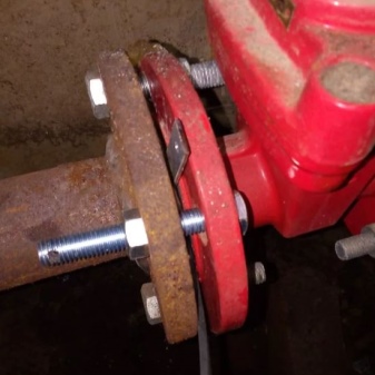
Before installing the throttle washers on the heating system, it is performed according to the drawings in the form of a steel disk cut from sheet metal with a thickness of 2-4 mm. The calculated hole is drilled strictly in the center. The minimum permissible diameter on the washer is limited by regulations and must be at least 3.0 mm. The thickness of the non-adjustable washer for pipelines with an outer diameter of up to 89 mm is taken from 2 to 3 mm, over - from 3 to 4 mm.
The calculated hole of the adjustable washer has an oblong shape. This design has two rods that are diametrically opposed to each other. For the possibility of external control, they are taken out from the side through the sealing channels. Varying the positions of these elements changes the area of the hole in the structure. When they are fully pushed in, the minimum passage diameter is 5.5 mm, and when fully open, the passage diameter will be 18.0 mm. Such devices are supplied with special keys for performing adjustment operations.
In addition, it is very important to know that in such a design it is possible to establish restrictions for the movement of the rods and its sealing. This is done so that consumers cannot independently change the flow area of the device, thereby interfering with the operation of the heating network, causing its imbalance.
The domestic industry produces the following types of throttle washers for adjusting the modes of the heating network:
- The first modification is carried out in the form of a housing, on which a disc is placed with a through hole. When adjusting, you need to turn the stem, after which an element similar in configuration to a truncated sphere rotates the movable disk with holes made in its cavity. A flaw in the device - possible jamming during the adjustment of the movable disk. In addition, the design of the device is quite complex, it has a lot of parts and assemblies, it is practically impossible to independently perform such a design, and during operation, every extra part operating in the zone of high temperatures and fluid velocities increases the threat of failure of the entire structure.
- The next type of limiting device is made from a set of throttle parts made with flanges. The modification has the advantage of the possibility of self-sealing of all parts during installation. The design is simple and reliable. To adjust the flow rates of the coolant, it is enough to mount the required number of washers and secure them with a nut. Since the installation of the washer is carried out on the supply pipeline, in the heat well or on the elevator unit of the consumer, such devices are installed exclusively in the summer, during the repair of heating networks, after the water has been drained from the building heating systems.
Adjustment
The adjustment of the heating network takes place in several key stages. At the very beginning, a plan for adjusting the heating system is being developed. It should be remembered here that each heating system, in its essence, is unique, even if it invariably adheres to all state standards of world quality. It is thanks to them that there are several basic patterns between the systems, but this does not exclude the need to carry out a hydraulic calculation of the network at the very beginning of work. There are several calculation methods in this case.
- Manually without using automated computer systems. The calculations will require utmost care and will relate to each section of the heating network.The calculation results in this case have a purely theoretical background, and any error can lead to an incorrect assessment of the entire state of the heating network as a whole.
- The second method is almost all the same, but here you can use numerical computers and get the results of calculations in just a few minutes. A mistake can be made here only if the initial parameters are incorrectly set in the computational program.
- Specialized organizations can also help in the calculations, which guarantee the quality of the services provided and quick calculation using specialized software.


At the second stage, the option and the possibility of installing throttling washers on the heating network are determined. For this, the master also has several possible choices.
- According to the calculations, install the washers in the standard places - at the inlets and outlets of the pressure control. But such a solution is not suitable for all heating networks, some may simply stop working, and everything will have to start over.
- Make and install washers according to calculations. Here, not only their sizes, place of installation, but also their quantity are strictly regulated. In no case is it recommended to decrease or increase it in order to comply with the network load.
- Installing a balancing valve or orifice plate is a tricky choice for the user. But it is worth considering that a cheaper analogue may simply not fit purely physically based on the calculation of the hole. The installation should be as accurate as possible and with respect to the range, and it is better if the person already has at least a little experience in this.
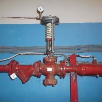
The heating system is then started up and tested immediately before the next step. And if the indicators differ from those shown in the calculations, the master may have several ways out of this situation.
- When using unregulated devices, it is better to recalculate all problem areas where a pressure or temperature failure is noticed. If there is no time to carry out a complete reinstallation, you can try to balance the system with additional washers with a specific thread for the situation in order to set the pressure to the optimal level. A complete reinstallation is possible only at the end of the heating season, since it becomes impossible to service subscribers during this period.
- Everything is much simpler if adjustable washers were used in the design. In this case, a complete recalculation and reinstallation is not required, and you can easily adjust each problem area separately, and then check all possible parameters.
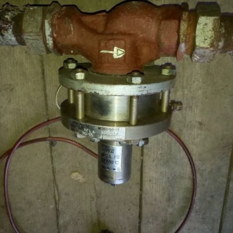
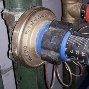
For information on how to correctly calculate the size of the throttle washers, see the next video.
How to install?
In addition to installation, it is very important to carry out the calculation correctly - these are two key stages that must be paid attention to.
Payment
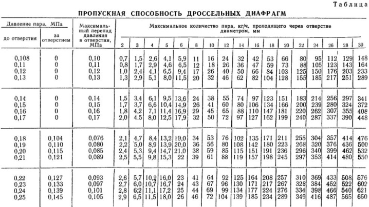
To carry out a calculation for a heating system means to take into account not only the diameter of the washer hole, but also several other key parameters. Despite the fact that only one single formula is used in calculating the pressure for water and gas, it still remains a complex and responsible process. The main role here will be played by the accuracy of the initial data, which guarantee uninterrupted thermal and hydraulic operation. Based on the calculations carried out, a washer is made with the required hole and section. The calculation can be carried out in two ways:
- manually;
- using specialized software.


Manual calculation is carried out according to the formula D = 10x? Р / ΔН, where the operand "P" determines the thermal flow rate at maximum temperature in both versions of the pipeline - supply and return, and the second determines the pressure that the diaphragm can extinguish in this system. The diameter of the washer in this case, according to state quality standards, in any case will not be less than 3 mm. If the hole is lower, and the diameter itself is smaller, there is a possibility of clogging it with small particles.Most often it is rust, and after a blockage, the heating system in a residential building will not work, in general, and all the work will have to start completely anew, with the preliminary removal of all water from the heating network.

The throttled head, which is damped by the diaphragm, is calculated from the pressure difference between the supply and back pressure in the pipes. Strictly speaking, this is the minimum and maximum indicator of indoor pipes. The hydraulic resistance is also taken into account, where the entire loss of pressure in heating networks is summed up. Hydraulic calculation is always the first step, and for each system it is carried out separately according to a number of mandatory recommendations:
- the water pressure when switched on must be at least 6 m;
- before calculations, the parameter of hydro loss of 1-2 m inclusive is taken into account;
- the size of the washer is always determined in advance and taking into account possible hydro loss, so that in the end it fits as tightly as possible;
- the maximum head should not exceed a parameter of 40 m;
- the hole of the washer is always slightly larger than the hole of the assembly, while it should turn smoothly and freely.
Installation
How to install the washer correctly? After performing the calculations and matching the dimensions, it remains only to attach it to the desired hole, securing its position with a nut. The fastening must be as tight as possible for the heating system to work. It is worth checking the reliability of the fasteners before starting the system!

Washers for the heating system - HOA Horizon Perm
Washering of heating networks is carried out in order to distribute the coolant flows between consumers in accordance with their needs. Without regulation, hot water from the heat source mostly enters the buildings located near the boiler room. The remaining small volume of water is directed to the periphery. Remote buildings lack heat, they freeze, while overheating is observed in nearby buildings. People, opening the vents, literally heat the street.
To prevent this from happening, limit washers with a calibrated hole of a smaller section than the pipeline are installed on the branches of the heating networks to the buildings. This makes it possible to increase the volume of the coolant for remote buildings.
Washers (hole sizes) are calculated for each house, depending on the required amount of heat. A positive result from washering heating networks can be obtained only in the case of 100% coverage of all buildings connected to the heating network. In parallel with washering, it is necessary to adjust the operation of the pumps in the boiler room with the hydraulic resistance of the heating network and.
Washer effect
After installing the washers, the flow rate of the coolant through the pipelines of the heating network is reduced by 1.5-3 times. Accordingly, the number of operating pumps in the boiler room also decreases. This results in savings in fuel, electricity, and chemicals for make-up water. It becomes possible to increase the temperature of the water leaving the boiler room. For more details on setting up external heating networks and the scope of work, see ... .. Here you need to give a link to the section of the site "Setting up heating networks"
Washering is necessary not only for the regulation of external heating networks, but also for the heating system inside buildings. Risers of the heating system, located farther from the heating point located in the house, receive less hot water, here it is cold in the apartments. It is hot in apartments located close to the heating point, since more heat carrier is supplied to them. The distribution of the coolant flow rates along the risers in accordance with the required amount of heat is also carried out by calculating the washers and their installation on the risers.
Stages of washering the heating system
First step
Inspection of the main pipelines of the heating system in the basement and in the attic (if any)
Drawing up an executive diagram of the heating system indicating the diameters of pipelines, their lengths, locations of fittings (in the absence of a project)
Collecting data on the internal air temperature in apartments, specifying which apartments are warm, which ones are cold
Analysis of the reasons for the unsatisfactory operation of the heating system, identification of problem risers (apartments)
Second phase
Hydraulic calculation of the heating system, calculation of washers
Development of recommendations for improving the work of a heating point, heating system
Installation of regulating washers on risers (this work can be carried out by the customer himself)
Stage Three
Checking the implementation of the recommended activities
Analysis of the new steady state after washering the heating system
Correction of the size of the washers in places where the desired result is not achieved (by calculation)
Removing washers requiring adjustment, installing new washers
Washers can be installed on internal heating systems both in winter and in summer. Check their work - only during the heating season.
Washer costs
The cost of washers is low - this is the cost of the washers themselves and their installation on risers. The cost of work on the regulation of internal heating systems depends on the thermal power of the building (the number of risers).
The minimum price is 40 thousand rubles. with a heat output of the heating system up to 0.5 Gcal / h. The price of regulating the heating system of a multi-section building can go up to 150 thousand rubles. The rise in the cost of work arises when there is no project documentation. In this case, it is necessary to make a full-scale survey of the heating system and its measurements (diameters, lengths of pipelines, location of fittings).
Throttle washer calculation
Purpose and device of adjusting washers ↑
The heating network diagram is a complex structure consisting of a boiler, pipe fittings, highways, batteries, a coolant distributor, circulation pumps and an expansion tank. The throttle washer in the heating system is needed to evenly distribute the hot water flow moving through the pipes. Without it, the coolant from the boiler or other heating source is unevenly distributed. That is, more hot water enters the rooms located near the boiler room, and its remainder goes to the distant rooms.
The throttle washer, mounted in the heating system on the branches of the pipeline, is a metal part with a selected hole that is smaller than the diameter of the pipe. Due to such control elements, it is possible to effectively heat the premises with the lowest energy consumption.
Due to the presence of washers in the heating pipeline of the building, the total flow rate of the coolant in the heating system is reduced by 1.5 - 3 times, from which the following advantages can be distinguished:
- the electrical energy required for the operation of circulation pumps is saved;
- reduced fuel consumption required to heat water to the required temperature in the pipeline;
- the temperature of the coolant at the outlet of the heat source rises.
Installing throttle washers in a heating system requires certain knowledge and skills. Therefore, such work must be performed by qualified specialists.
Installing the throttle washer ↑
In practice, the process of washering the heating pipeline is carried out in several stages.
- inspection for the uniform distribution of the temperature of the heating system, starting from the source and ending with a remote heating point;
- a diagram is drawn up indicating the diameters of pipes, valves and lengths;
- obtaining temperature data separately for each room;
- analysis of the shortcomings of the two-pipe heating network.
- throttle valves with holes are calculated;
- an algorithm for improving the operation of the heating system is being developed;
- throttle elements are installed on the pipeline branches - they are mounted in the places where valves are installed at the inlet to the consumer or in threaded pipe connections.
- checking the assembled heating circuit
- study of criteria for improvement after the installation of the washers;
- replacement of washers in places where there is no required indicator - replacement is performed with valves with a smaller or larger diameter, depending on the temperature at a specific section of the line;
Of the specified algorithm of the technological and technical process, the most important thing is the ability to accurately calculate the diameter of the washers. To do this, you need to use the numbers obtained from the calculations, which should be suitable for the reference data.
How is the throttle washer calculated ↑
The diameters of the throttle element holes are calculated by the formula:
When the calculation is performed, according to the provided formula, it is required to take into account:
• H- throttled head (m of water column);
• G - consumption of heat carrier fluid (t / h).
It is important to know that the heating system must be thoroughly flushed before installing the throttle diaphragms. To prevent the system from being forgotten by debris, it is required to mount washers of at least 3 mm
You also need to know that the dismantling of washers in systems under pressure is prohibited.
Setting the size of the washers must be done for each room. Maximum efficiency is achieved when they are installed on all circuits and in all rooms. In parallel with the installation of these elements, it is necessary to check the functioning of the circulation pumps and their compliance with the required standards.
Washering the heating network will distribute hot water to all rooms, depending on their needs. In this way, it is possible to heat the most distant points to the required temperature without further increasing the power of the heat source.
Aperture markings
Diaphragms are usually labeled with orifice size information. Typically, this information is stamped on the diaphragm shank. In addition to the size of the orifice, there may be other information, such as: the name of the manufacturer and the code of the material from which the diaphragm is made, the corresponding size of the pipe for installation in which this diaphragm is designed. This information is extremely important for the operator who has to deal with the replacement of diaphragms if damaged or due to the fact that it worked. The shank of the new diaphragm that is being installed must have the same marking with the information identical to the information of the old diaphragm being replaced.
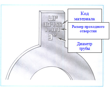 Diaphragm shank markings
Due to the fact that the diaphragms can be of a special design for correct trouble-free operation, it is necessary to place the bore in accordance with the project. Many manufacturers add the words "Up" or "Inlet" when marking all their diaphragms. Otherwise, in the absence of these words in the marking, the general rule for mounting all diaphragms is this: the diaphragm must be installed in such a way that the side with the marking is the inlet for the flow passing through the diaphragm. The orientation when installing unmarked diaphragms is determined based on the type of bore ribs.
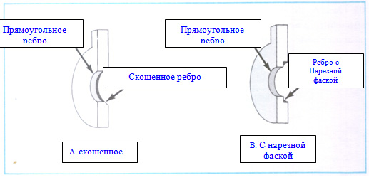 Bore Diaphragm Rib Types
The illustration above shows, as an example, two diaphragms with the following types of bore ribs: a beveled diaphragm rib and a recessed chamfer cut along the edge of the rib. In both cases, the rib of the passage hole on the other side of the diaphragm is usually rectangular, without bevel or chamfer.
In both cases, when installing orifice plates with markings, and when installing diaphragms without markings, the diaphragm should be installed so that the flow enters the diaphragm from the side of the normal rectangular rib of the bore. The beveled or chamfered edge of the bore should be located downstream of the orifice plate.
Calculation of the parameters of gas flow through the throttle washer (L 2;
P0 - pressure in front of the orifice plate;
P1 / P0 - pressure ratio before and after the orifice plate;
e - consumption coefficient;
On the auxiliary graph for determining the flow coefficient at the inlet to the orifice (ein)
F1 / F0 - ratio of the orifice area of the orifice plate to the area of the passage section of the channel in front of the orifice plate.
On the auxiliary graph for determining the flow coefficient at the outlet from the throttle hole (eout)
F1 / F0 - the ratio of the orifice area of the orifice plate to the area of the passage section of the channel after the orifice plate.
Gas consumption for subcritical flow regime:
G = e F P0 [(2 g / (R T)) (k / (k-1)) ((P1 / P0) 2 / k - (P1 / P0) (k + 1 ) / k] 0.5
Gas consumption for supercritical flow regime:
G = e · F · P0 · [(2 · g / (R · T)) · (k / (k + 1)) · (2 / (k + 1)) 2 / (k-1)] 0, 5
The critical pressure drop (at which the transition from subcritical to supercritical flow occurs) is determined by the formula:
To construct a system of nomograms, these formulas for finding the gas flow rate were divided into the following complexes:
C-ex A = e · [2 · g / (R · T)] 0.5
For subcritical mode - C-ex B = [(k / (k-1)) · ((P1 / P0) 2 / k - (P1 / P0) (k + 1) / k] 0.5
For supercritical mode - C-ex B = [(k / (k + 1)) · (2 / (k + 1)) 2 / (k-1)] 0.5
The adiabatic exponent is calculated by the formula k = (Cv + R) / Cv = 1 + (R / Cv) or we choose from the table
Number of degrees of freedom
Scheme of work with the system of nomograms
To select the required parameters, we use the following system of nomograms: 
The basic system of nomograms consists of four nomograms. Nomograms 1 and 2 have additional systems of nomograms, consisting of three nomograms. For the first nomogram, this is the determination of the flow rate e (Y-axis), which is the sum of the flow rates at the inlet and outlet of the orifice plate, which in turn depend on the ratio of the areas and the Reynolds number (10 4). Also, for the first graph, an additional nomogram is used to determine the product of RT (gas constant and gas temperature in K).
For the second nomogram, an additional system of nomograms is used to determine the C-ex B complex. This complex is calculated using different formulas for the subcritical and supercritical flow regimes. Knowing the value of the adiabatic coefficient k, according to the lower graph of the additional system of nomograms, we determine the critical pressure drop for a given washer. If the selected pressure drop across the washer is less than [P1 / P0] cr, then the flow is supercritical and the C-ex B complex is determined by the right auxiliary graph and depends only on k. If the difference we have chosen is greater than [P1 / P0] cr, then the flow is subcritical and C-ex B is determined by the left nomogram and depends on k and P1 / P0.
The following parameter ranges are common to all variants:
d = 0.2. 1.9 mm P0 = 0.4. 35 kgf / cm 2 T = 200. 2500K
e = 2.14 RTx10 -3 = 0.2. 7.5 G = 0. 400 g / s
Commissioning calculation of heat consumers, throttle washers and elevators
Subsystem "Adjustment" GCI "CityCom-TeploGraf"
This subsystem is a toolkit for calculation of adjustment devices, the installation of which allows balancing the hydraulic regime in the heating network, ensuring uniform heat supply to consumers and the hydraulic stability of the heating network and the heat supply system as a whole.
Calculation of constriction devices (throttling washers and nozzles of elevators) by the types of connected heat load on consumers suggests a much more detailed description of subscriber inputs than with a simple hydraulic calculation and modeling of a heat network. Therefore, the subsystem includes the corresponding extensions of the consumer certification database, as well as the necessary additional input procedures.
The calculation of the adjustment devices is carried out on the hydraulic model of the heating network calibrated in the nominal mode. As a result of the commissioning calculation, analytical documents are generated containing all the necessary data on the hydraulic characteristics of consumers and the parameters of the hydraulic regime, as well as the resulting document with the calculated design parameters of the restriction devices - head and retaining diaphragms, as well as elevator nozzles and washers by types of connected heat load.
In addition to the actual adjustment of subscriber inputs, the subsystem also allows simulating the adjustment of the hydraulic regime by pressing the valves in heat chambers with the simultaneous calculation of the diameters of equivalent washers corresponding to the “pressed” fittings for their installation at regulated points of the heating network (recall that the rules for operating heat networks categorically prohibit regulation of the mode by pressing the shut-off valves).
Adjustment of the hydraulic regime in accordance with the calculation obtained using the "Adjustment" subsystem allows obtaining a real technical and economic effect, expressed in stable and uniform satisfaction of consumers with thermal energy while reducing the required heat supply from the source, and also in a significant reduction in electricity consumption for pumping the coolant.
Net savings from the introduction of settlement adjustment activities may amount to 5. 35%, depending on the initial state of the heating network and subscriber inputs.
