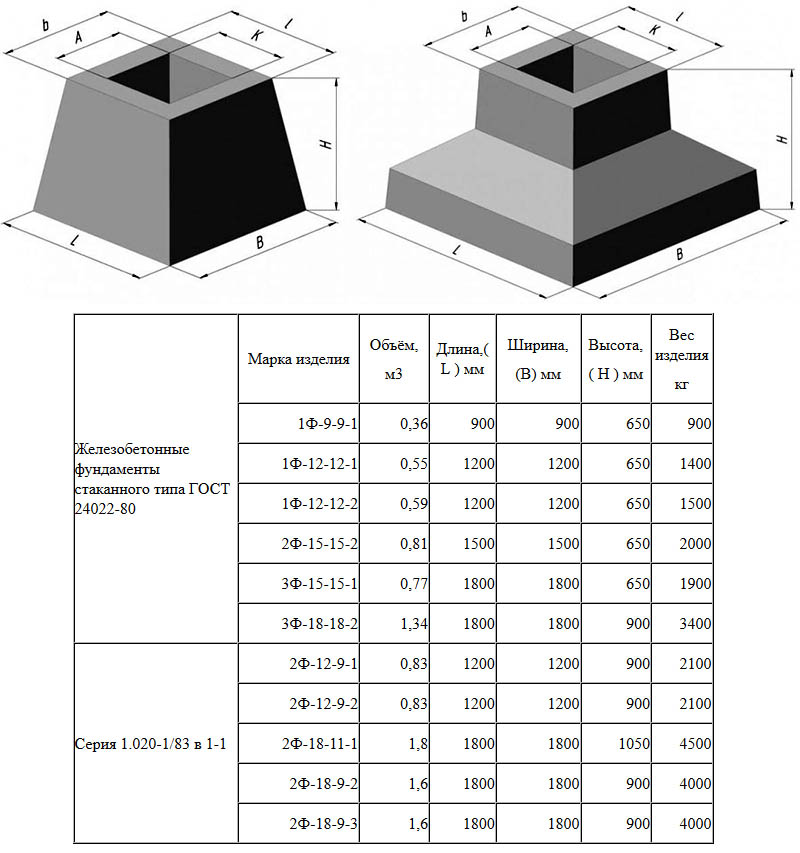
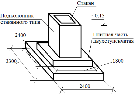
Calculation of foundations for columns
Installation diagram of steel columns on foundations
Such foundations are always calculated for a specific geodetic support. For the correct provision of geodetic parameters, the vertical and horizontal height positions of the bolted connections are monitored. Ready-made templates or a special jig are perfect for such purposes.
Templates are metal or wooden frames of specific sizes, in which there are already ready-made sockets for future anchors. They are connected along the formwork with the axes of the monolithic foundation, and are fixed.
The templates must be installed absolutely level, therefore an additional measurement of the vertical is carried out using a building level or level. In some cases, it will be justified to use welding, when the templates are rigidly installed on the reinforcement of a monolithic concrete pad.
Now, when erecting foundations for metal columns, they began to practice anchor connections installed in wells. Such recesses are sealed last, because the bolt head is measured with geodetic instruments, its position and horizontal location are specified.
All monolithic cushions are connected to the columns using powerful anchors, because the load on the cushion is enormous through a large distance between the columns. Therefore, in addition to connections, special building straps are additionally used and the connection of structures in the upper position on the grillage. The straps consist of:
- Metal frame for fixing bolt patterns.
- Metallic templates. They are used for direct fixation of structures, installation of anchors and bolted connections.
You can also install metal frames, grips and clamps on a concrete base, connect them to each other. After all the reinforcing elements are connected to each other, the structure is poured with concrete and left to dry for a month. In this case, all templates and conductors are dismantled.
How is the calculation of the column foundation done
Monolithic columnar foundation for a metal column
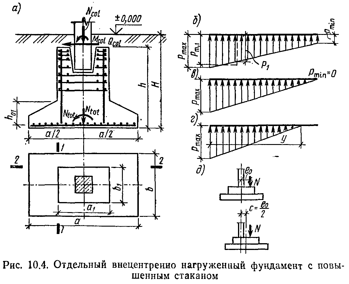
As a rule, the calculation of the foundation for a metal column implies whether the soil is able to withstand the design load of the foundation with which it will act on a square centimeter of the area, and the collection of all data on future construction. In fact, you need to get complete information about the building, soils and groundwater, collect and systematize the data obtained and, on their basis, transfer the finished project to the builders. For this you need:
- receive from the architect the project of the future building, the specification of building materials and communications;
- calculate the total support area;
- collect all the parameters, systematize them and get the actual design pressure of the building as a whole.
How do you know the load that the building itself will create? To do this, you need to obtain detailed data about the building itself, to collect the mass and characteristics of all materials that can be used in its construction, as well as projected communications, future furniture, the amount of snow on the roof. This calculation consists of several parts:
- Calculation of building floors and steel columns. First you need to find out the mass of the metal column itself, because it also, albeit slightly, creates pressure on the ground. This requires calculating the volume of the structure. This is done according to the geometric formula for calculating the volume of a cylinder. This gives the volume, which is then multiplied by the density of the metal to obtain the mass of the steel column.
- Then you need to find out the mass of the floors. As a rule, these are manufactured products and each manufacturer already indicates their weight.Therefore, it is enough to contact the suppliers.
- There are times when a grillage structure is installed on metal columns. Its mass is also not a problem to calculate, because for this it is enough to know how much concrete or ready-made concrete structures will go to the construction of the grillage.
- Calculation of the mass of the walls. Much depends on the material, because a brick weighs less than concrete, but more than foam blocks. Accordingly, it is worth collecting data on all building materials used in the construction of the building.
- Roof calculation. This includes the specification of the materials from which the attic is made, as well as the specification of all roof materials, right down to the outer covering. When designing a structure, the architect provides a detailed specification, so it will not be difficult to calculate the total mass of the structures.
- After summing up all the data received, a figure will be calculated that characterizes the maximum permissible load on the foundation supports.
To find out what force is pressing on a unit of support area, you need to know its overall dimensions. If the steel post has a square section of 50 x 50 cm, then the support area will be 2500 cm². Then the pressure that will act on a unit of soil area is calculated by dividing the mass of the building by the area of one support.
But there is always a rule: a larger number of supports will not be superfluous, therefore, designers often install supports with an interval of approximately 1.5 - 3 m.This is done in order to provide the necessary reserve of strength for structures associated with unauthorized completion, arrangement of premises or the installation of heavy industrial equipment ... As a rule, in the calculations, a mandatory 50% safety margin for each support is provided.
Using anchors when laying supports
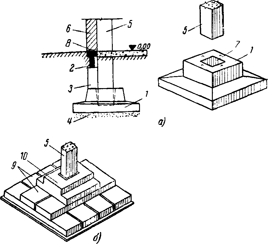
The foundation for a metal column is laid using anchor bolts. These anchors are laid directly in the support itself. Laying must be carried out under strict control and with precise breakdowns. Permissible deviation approx. 2 mm.
All anchors are installed on axles and fixed at the very top of the formwork. An important step is control over the installation of such bolts. The height of the position must be monitored. To do this, use a template or a conductor. It helps to install all bolts correctly. A template is a special frame made of metal or wood. It contains special sockets for attaching bolts. There are also special risks on it, with the help of which it is attached to the formwork to the axes along the entire support.
Not so long ago, anchor bolts began to be placed in wells, which are left in the structure and are sealed after the entire installation. Anchors of large sizes and with significant weight are laid in supports under very tall buildings (they are used for columns of industrial buildings). To keep them, some devices are made. When installing such devices, frames are used, which are used to support templates with anchor devices in the required position when pouring concrete, and templates that are used to attach the anchors.
The anchor device is very difficult to install. The fasteners are made with high precision and are very reliable. When laying, it is the measurements and markings that are considered the most difficult task. For reliability and greater accuracy, special templates are made, which are called conductors. These are essentially such devices in the form of frames, which are made from metal pieces. On this frame, the axes are precisely drawn, holes are made to mark future mountings. If light bolts are used in the work, then such a jig can be made of wood.
The calculation of the metal column must be accurate. Such structures are very strong, and if there are errors or deviations from the required dimensions, it is very difficult to fix them.
Features of the foundation for metal columns
There are buildings with increased strength requirements. These are buildings related to industrial and energy facilities.
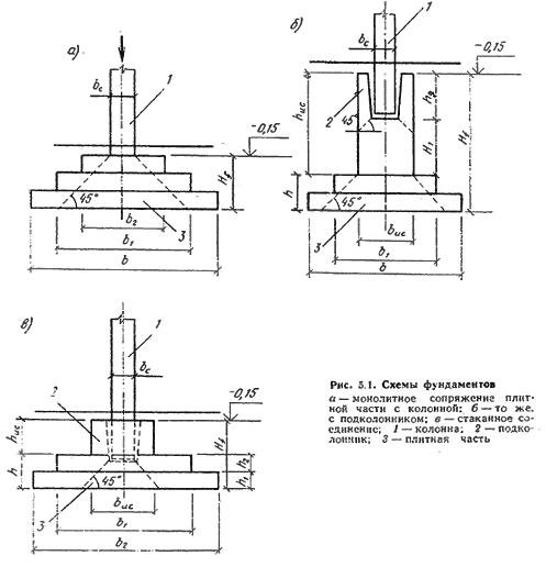
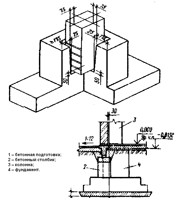
As a rule, a columnar foundation is used here for a frame-type metal column, when the load from the building falls on metal pillars installed inside a bowl made of concrete. The peculiarity of the foundations for steel columns is that a pillow is preliminarily prepared, inside which a recess is made. This is where the column will be attached by anchoring.
Construction stages
The use of metal pillars does not imply the presence of prefabricated structures. Otherwise, an additional calculation of the bearing characteristics of the structure would have to be done.
The best option is to use a monolithic concrete foundation. The specified type of base is stronger, quickly poured. The construction process is divided into the following stages:
Pre-calculate the maximum permissible loads exerted on the base cushion;
The marking of the points where the columns will be installed is carried out. Then earthworks are carried out;
A well is being dug. The length and size of the pit depends on the section of the metal column and the estimated depth;
Now you need to make the outer formwork. For this, boards are taken, it is recommended to use plywood with a moisture-resistant coating. As a rule, such formwork is not removable;
A pillow is made of sand and gravel. Previously, the surface of the soil is leveled, then sand is poured. The layer is not more than 15 cm, it is carefully rammed. Crushed stone is poured on top. The layer is no more than 20-25 cm. It is also carefully rammed and leveled horizontally;
The next step is to create a reinforcing belt, which will be the main one. Metal rods are installed around the perimeter of the pillow. The armature is positioned both vertically and horizontally;
Now the prepared foundation pit is filled with concrete mortar.
It is important to use concrete grade 200M. Before starting the solution, it is necessary to establish geodetic levels, as well as elevation marks
These will be the pointers where the metal columns will be placed. Also, these pointers will help when carrying out repair work on the foundation, due to subsidence.
Anchor connections are installed inside the recesses, with the help of which the steel elements are fastened. But here, too, there are some peculiarities.
The reliability and strength of the fastening is checked as follows: after the anchors are welded to the reinforcing layer, the concrete base is broken and the condition of the bolts is examined. If the latter remained in place, it means that the installation was carried out correctly and the construction can continue. In the case when the structure deviated from the center even by 2 millimeters, it becomes necessary to replace the anchor bolts. Compliance is checked after each installation. Otherwise, the erected structure will be unstable and can lead to the destruction of the building.
Significant foundation requirements
In typical construction, frame buildings are erected only for industrial purposes. With the development of the segment of individual buildings from several floors of a large area, bearing supports in the form of columns have become in demand both in the houses themselves and in adjoining structures (balconies, fences, sheds, a garage for several cars).
Often, the frame structure of the outer walls, the support of the floors, is made in the form of pillars from a reinforced monolith with filling the gap between them with light aerated concrete blocks. Uneven subsidence of concrete pillars will lead to cracking of the wall material. Therefore, you need to take a responsible approach to the correct foundation arrangement under the supporting elements, which are made in the form of pillars.
The main document for such construction will be "Guidelines for the design of foundations on a natural basis for the columns of buildings and structures of industrial enterprises."
 Finished reinforced concrete products
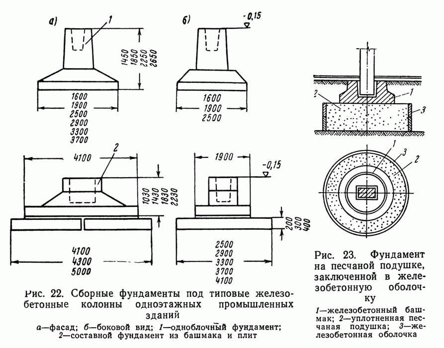
When designing the supporting part of the building, standard prefabricated elements with already known characteristics and mounting loops for quick installation can be taken into account.
Main characteristics of cranes
When designing new structures, the main
the characteristics of the cranes should be taken according to the standards of the types, the main
parameters and dimensions (so far, such standards are available only for special
cranes with flexible suspension of the traverse and for several types (metallurgical
cranes) or according to the technical conditions of factories of lifting and transport equipment
(ZPTO), producing cranes: general purpose - tab. and special - tab. ... At
reconstruction, these characteristics should be taken according to passport data
installed cranes. The characteristics of previously produced cranes are also given
in the Crane Handbook. T. 2. Characteristics of cranes, crane mechanisms, their
units and parts, technical operation (L., 1973).
Table 1
Basic parameters according to the picture
Indicators (no more) at operating mode
crane
LTO, m
not less
average
heavy
ATO,
mm
V, mm
TTO,
T
MT, T
Pmax,
kN
TTO,
T
MT, T
Pmax,
kN
Bureysky ZPTO
16,5
3500
5120
11
2
65
12
2
73
5
22,5
5000
5910
16
2
77
17
2
82
28,5
5000
5910
22
2
94
24
2
100
Alexandria ZPTO
16,5
4000
5260
11
2
55
12
3
57
5
22,5
4000
5260
13
2
60
14
3
62
28,5
4200
5460
19
2
75
19
3
76
16,5
4350
5600
13
3
84
14
4
89
10
22,5
4350
5600
16
3
93
18
4
99
28,5
4600
5850
21
3
105
22
4
110
16,5
4350
5450
19
4
133
19
5
139
16
22,5
4350
5450
21
4
142
21
5
149
28,5
4600
5700
27
4
161
27
5
166
16,5
4350
5450
20
5
138
20
6
144
16/3,2
22,5
4350
5450
22
5
147
22
6
154
28,5
4600
5700
28
5
166
28
6
171
PO "Crane" (Uzlovaya)
16,5
4400
5600
22
7
188
26
7
195
20/5
223
4400
5600
28
7
195
32
7
210
28,5
5000
6200
38
7
235
42
7
240
16,5
4400
5600
30
10
260
34
10
270
32/5
22,5
4400
5600
36
10
275
40
10
290
28,5
5000
6200
45
10
305
47
10
305
Kharkiv ZPTO
16,5
5250
6500
41
14
364
50
16
380
50/12,5
22,5
5250
6500
49
14
387
58
16
440
28,5
5250
6500
60
14
421
71
16
470
Notes: 1. Values
crane weight TTOand carts TTrounded
up to 1 t.
2. The highest wheel load is indicated Rmax.
3.
For cranes operated outdoors, some
base increase V (as well as the height of the crane), with an increase TTOand Rmax.It
changes the load slightly (within the strength of the calculation of building structures and
grounds).
table 2
Basic parameters according to the picture
Indicators (no more)
LTO, m
not less
ATO, mm
BTO, mm
mTO, T
mT, T
Pmax,
kN
Magnetic cranes
16,5
3500
5070
15
2
75
5
22,5
3500
5070
19
2
87
28,5
5000
5910
26
2
109
16,5
4400
5380
15
3
91
10
22,5
4400
5380
18
3
100
28,5
5000
5980
24
3
113
16,5
4400
5600
29
6
171
15
22,5
4400
5600
34
6
190
28,5
5000
6200
43
6
212
16,5
5300
6500
30
8
202
20/5
22,5
5300
6500
38
8
220
28,5
5600
6800
47
8
246
Clamshell cranes
16,5
4400
5380
16
3
83
5*
22,5
4400
5380
18
3
91
28,5
5000
5980
24
3
105
16,5
4900
6100
33
9
165
10
22,5
4900
6100
41
9
197
28,5
5000
6200
50
9
210
15
22,5
6000
7250
50
14
245
28,5
6000
7250
62
14
280
20
22,5
5250
6500
50
18
281
28,5
5250
6500
60
18
320
Magnetic grab cranes
16,5
3800
4960
15
2
101
5/5
22,5
3800
4960
20
2
116
28,5
4850
5860
25
2
131
16,5
4900
6200
42
9
136
10/10
22,5
4900
6200
50
9
207
28,5
5000
6300
58
9
230
15/5
22,5
5650
6900
36
—
295
28,5
5650
6900
74
—
332
20/5
25
7500
8700
50
13
265
31,5
7500
8700
54
13
310
Notes: 1. All taps
heavy duty, except for the marked * - very heavy duty.
2. See note. to table ...
Reducing the deformability of the base
At
the performance of construction and installation work must be guided by the general
rules and requirements established by applicable regulatory documents.
In this case, measures should be taken to reduce the influence of initial deformations
grounds for the deviation of load-bearing structures from the design position during the period
operation, for which it follows:
to communicate
the design organization about all deviations found during excavation
actual soil conditions from those adopted in the project;
provide
drainage of surface water from the site during construction;
not
disrupt the natural composition of the soil under the base of the foundation or unpaved
pillows;
prevent
soaking the base under the base of the foundation;
not
allow freezing of the base;
produce
preliminary running-in of the overpass with a crane.
Running in
overpasses are carried out with a loaded crane during 5-6 shifts of continuous work with
so that the crane passes over each column about 1000 times.
The running-in of multi-span flyovers should be carried out simultaneously in all
spans. Final alignment and fastening of crane rails, and in case
necessary - and crane beams is made after the end of running.
Stages of the foundation
 When marking the site, it is advisable to use geodetic equipment
After the work on the project of the future building is completed, you should proceed directly to the construction work. First of all, the design drawings are transferred to the area.
The construction site is divided using centerlines - thin wire or twine, stretched over pegs.
These pegs are installed in such a way that the center lines, crossing each other, form the perimeter of the future building. Then earthworks are carried out. Their nature and volume completely depend on the type of the designed foundation.
To evenly distribute the weight of the building on the supports, it is necessary to calculate as accurately as possible on the terrain the points of the foundations under the pillars.
Below we will consider the features of the device of monolithic foundations for columns produced using various technologies.
Columnar monolithic base
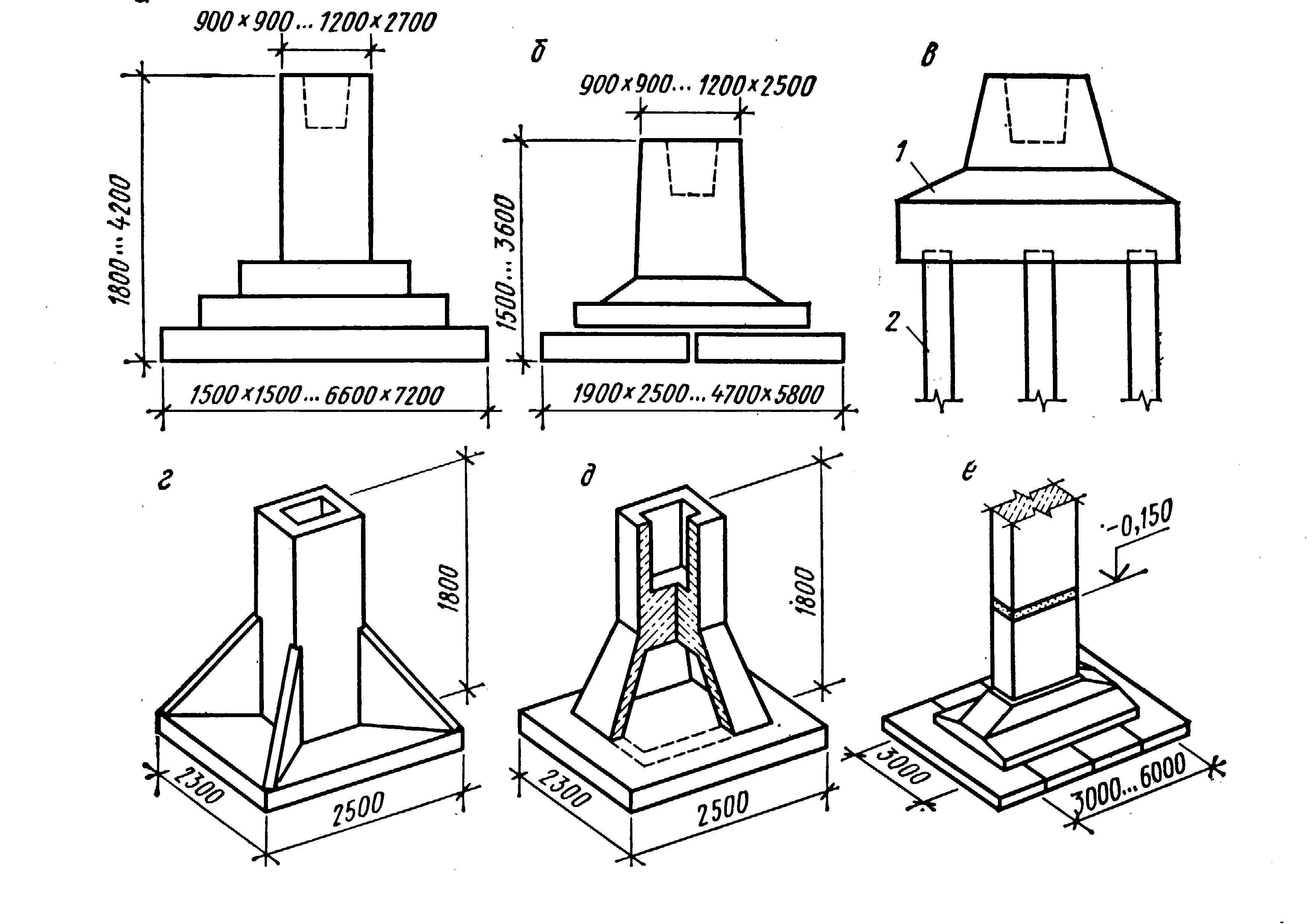
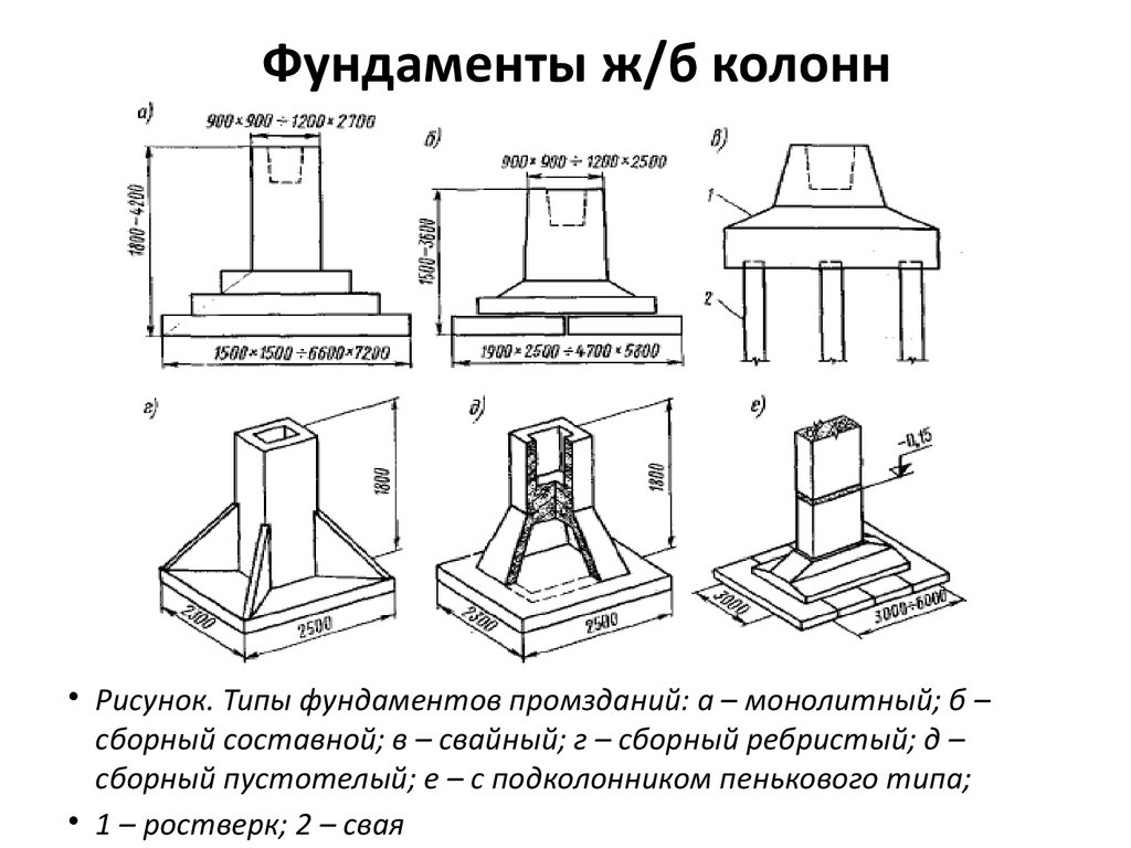
For the installation of a columnar monolithic foundation, it is enough to dig a hole of the required depth for pouring a monolithic glass, or to install a ready-made "glass". A sand and gravel cushion is also built at the bottom. Before pouring the monolithic columnar foundation, the point of installation of the column is measured and the formwork is constructed.
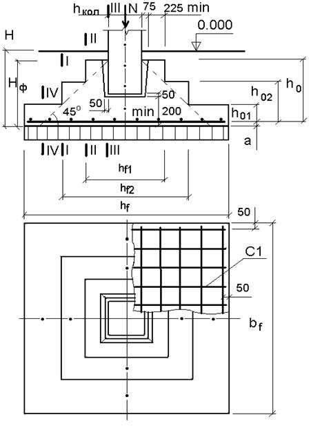
A frame is placed inside it with a mortgage or with pins protruding upwards for fastening the future support. Structurally, the columnar base can be made both in the form of a monolithic slab, and in the form of a stepped pyramid of two or three ledges. In the latter case, each step is poured separately, starting from the lowest.
Watch a video on how to install a column in a glass.
Monolithic tape base
In this case, a trench is dug around the entire perimeter of the building, as well as where the internal load-bearing walls will pass. At the points of installation of the columns, extensions or depressions are made in the ground, if the project provides for the installation or pouring of concrete "glasses" in these places.
 Column strip construction
If the total mass of the building under construction is not so large, you can do without such a strengthening of the structure. It will be enough to only strengthen the frame at the points of mounting of the bearing supports with the help of thicker reinforcement, the release of vertical rods or the installation of metal plates - "embedded".
Around the entire perimeter of the trench, a pillow of coarse sand, gravel or crushed stone is poured onto the bottom, and then a volumetric frame is laid. It is assembled and mounted in such a way as to rise above the trench level to a certain height (at least 30-40 cm), which is necessary to protect the walls of the building from melt and rainwater flows. The protruding part of the frame is taken into the formwork.
Solid monolithic base
To pour a solid reinforced concrete slab, it is necessary to remove the topsoil over the entire area of the future building. Then the site is leveled horizontally and covered with crushed stone, sand or gravel. A volumetric frame is laid on top of the sand and gravel cushion, the frame is also reinforced at the mounting points of the supports, rods (anchor bolts) are produced or a metal embedded plate is mounted.
We recommend watching a video on how the column is installed on the finished base.
Pile monolithic foundations
By the type of device, such bases can be of several types, but perhaps only bored technology can be attributed to monolithic foundations for columns. In the places of installation of future columns, a hole is made with the help of a drill, where the formwork is installed.
It is better to install embeds, anchors or outlets of reinforcement for the future column before pouring the monolith. In this case, it is possible to fasten these parts to the frame, which makes the connection of the column to the base more durable. In addition, it will take much less effort and time.
Since the reliability of the building and the durability of its operation depend on the correct choice of the foundation, it is necessary to approach the calculations very responsibly. The best option would be to contact specialists who can draw up a project taking into account all the smallest nuances.
Technical features of the device of such a base
Such foundations must fully comply with building codes and GOSTs. Their purpose is to transfer the total mass of the building structure through reinforced concrete supports to the base, and then to act on the soil. Accordingly, all foundations can be conditionally divided into the following groups:
- Base for supports with a permissible section up to 300x300 mm;
- Foundations for columns with a section of 400x400 mm.
There are other options for reinforced concrete foundations, but their thickness, dimensions and immersion depth are calculated individually. It should also be noted that the columns are used in the construction of massive industrial buildings, in the restoration of architectural monuments, as well as buildings on quicksand and karst sediments.
In some cases, to determine the type and arrangement of a specific foundation for a general-purpose building, it is necessary to carry out calculations for each support individually, since such bases in most cases are not connected to each other by reinforcement and concrete mortar.
 Installation of reinforced concrete columns.
The main types of foundations for supports, depending on the purpose:
- Wireframe. Used for the construction of general purpose structures;
- Frameless - for small private houses;
- Reinforced concrete and concrete - for industrial and private buildings of high altitude, which are built taking into account height differences in tiers, as well as in the presence of different types of soil in the section;
- Rubble bases for supports. They are used in restoration work, as well as to provide a decorative component of the future design.
The main materials used in the construction of the base:
- Concrete;
- Reinforced concrete;
- Rubble concrete;
- Rubble masonry.
It is clear that when choosing a material for the base, the builder starts from the maximum allowable loads on the pillow and the purpose of the building itself. There are also several types of foundations for supports: strip, columnar, pile and solid monolith.
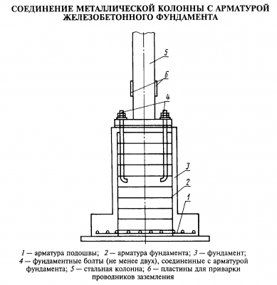 Connection of metal columns with reinforcement of a reinforced concrete foundation.
At the same time, steel posts are attached to the base using special bolts and anchors, the fasteners must be poured with concrete. Such a structure can sometimes be found in the construction of frame-monolithic buildings, when there is reinforcement in the base itself, as well as in general-purpose buildings.

