Foundation settlement
You are here: Reconstruction of a wooden house => Foundations and foundations => Example of calculation of a foundation => Settlement of a foundation
Calculation example
Below, as an example, is the calculation of the settlement of the foundation of the reconstructed wooden house. (see description of the foundation and soil conditions at the construction site, see columnar foundation on a sand bed).
Solution
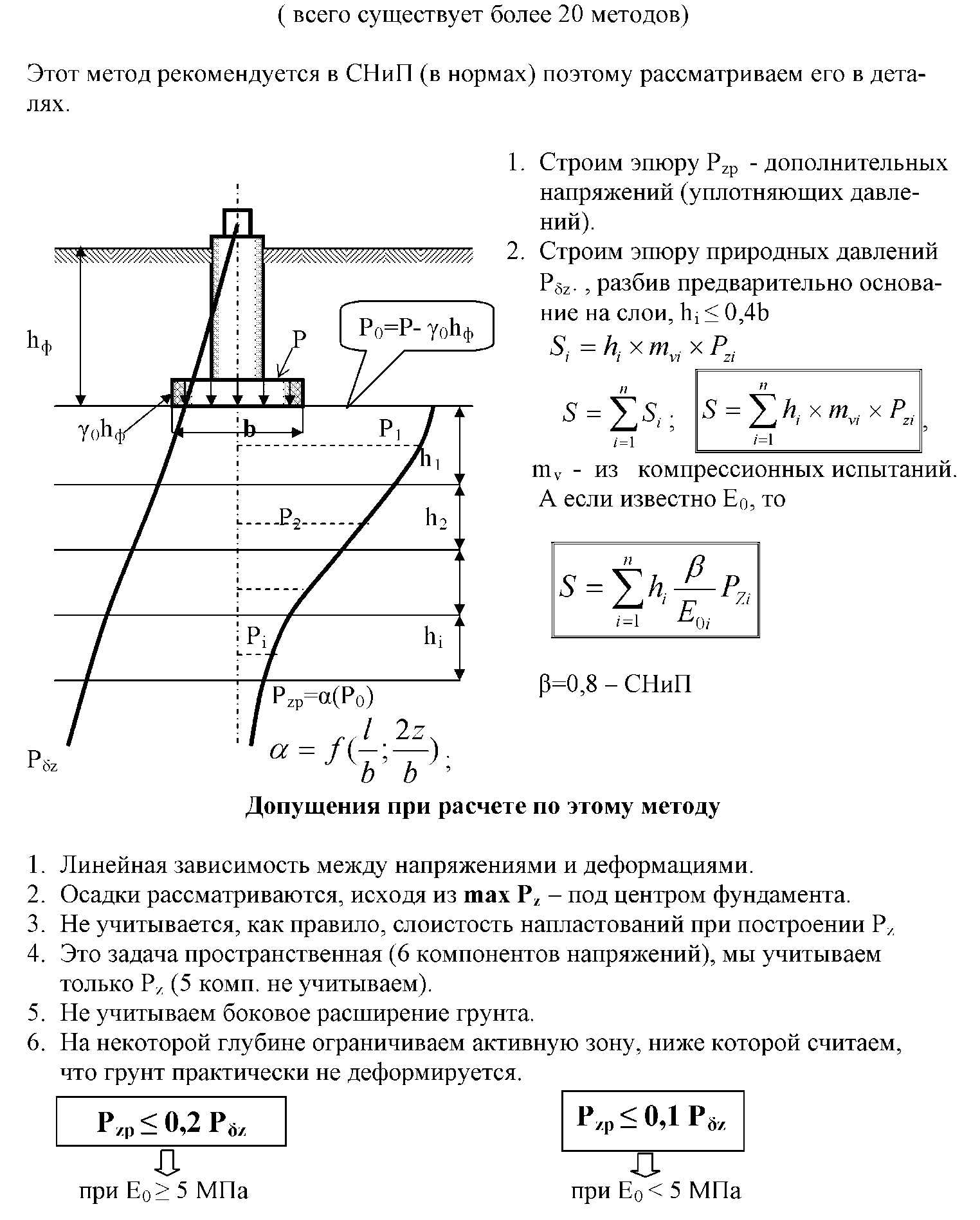
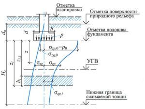
The settlement of the foundation base s, cm, using the design scheme in the form of a linearly deformable half-space (see clause 5.6.31) is determined by the layer-by-layer summation method according to the formula (5.16)
s = β∑ni = 1 (σzp, I - σγ, i) hi / Ei + β∑ni = 1 σzγ, Ihi / Eв, i (5.16)
- Determine the average pressure under the sole with the main combination of loads for calculating the foundation of a reconstructed wooden building for deformations p = 88.26 kN
- We accept, with the width of the foundation at b = 0.2 m, the height of the elementary soil layer hi = hi, min / 2 = 0.04 m, taking into account that, according to the value of h, included in the forumula (5.16) should be no more than 0.4 width foundation: hi, min ≤ 0.4b = 0.4 × 0.2 = 0.08 m.
- Determine the weighted average specific gravity of the soil γ ’layers I and II, lying above the foundation of the foundation
γ '= (γ'1h1 + γ'2h2) / (h1 + h2) = (12.0 × 0.2 + 18.4 × 0.4) / (0.2 × 0.4) = 1.63 kN / m3
- where γ'1 and h1 are the specific gravity and thickness of layer I, respectively; γ'1 and h1 are the specific gravity and thickness of layer II, respectively;
- Using the formula (5.18), we find the natural stress at the level of the base of the foundation:
σzg, 0 = γ'd = 18.4 kN / m3 × 0.6 m = 11.6 kPa.
- Interpolating, we determine the coefficients αi for rectangular foundations with the aspect ratio η = l / b = 0.4 / 0.2 = 2, α is the coefficient taken according to table 5.8 SP 22.13330.2011, depending on the relative depth ξ equal to 2z / b;
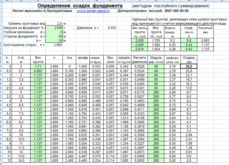
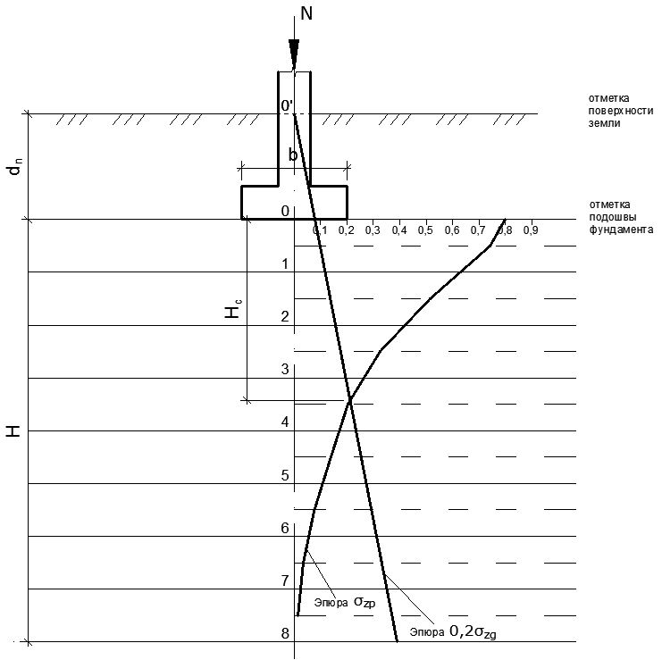
Using the formula (5.8), we determine the stress values σzg, i in the elementary layers from the proper weight of the overlying soil layers and from the external load σzp, i at the depth z. The lower bounds of the compressible thickness of the base Hc is determined graphically as the ordinate, the point of intersection of the σzp curve with the straight line 0.5σzg. To simplify the calculation, we neglect the decrease in stresses from the own weight of the soil taken out in the pit. The calculation results are shown in the table below.
| z, m | ξ | α (η = 1.8) | α (η = 2.4) | α (η = 2.0) | σzp, kPa | σzp, sr, kPa | σzg, kPa | σzg, sr, kPa | 0.5σzg, sr, kPa | s, cm |
| 1 | 1 | 1 | 100,30 | 99,06 | 9,76 | 9,95 | 4,97 | 0,02 | ||
| 0,04 | 0,4 | 0,975 | 0,976 | 0,975 | 97,82 | 92,51 | 10,52 | 10,89 | 5,45 | 0,02 |
| 0,08 | 0,8 | 0,866 | 0,876 | 0,869 | 87,19 | 79,92 | 12,03 | 12,60 | 6,30 | 0,02 |
| 0,12 | 1,2 | 0,717 | 0,739 | 0,724 | 72,65 | 65,88 | 14,30 | 15,05 | 9,13 | 0,01 |
| 0,16 | 1,6 | 0,578 | 0,612 | 0,589 | 59,11 | 53,47 | 17,18 | 17,57 | 8,69 | 0,01 |
| 0,2 | 2 | 0,463 | 0,505 | 0,477 | 47,84 | 43,43 | 21,10 | 22,23 | 11,12 | 0,01 |
| 0,24 | 2,4 | 0,374 | 0,419 | 0,389 | 39,01 | 35,50 | 25,64 | 26,96 | 13,48 | 0,01 |
| 0,28 | 2,8 | 0,304 | 0,349 | 0,319 | 31,99 | 29,30 | 30,93 | 32,44 | 16,22 | 0,01 |
| 0,32 | 3,2 | 0,251 | 0,294 | 0,265 | 26,61 | 24,47 | 36,98 | 38,68 | 19,34 | 0,00 |
| 0,36 | 3,6 | 0,209 | 0,25 | 0,223 | 22,33 | 20,63 | 43,78 | 45,67 | 22,84 | 0,00 |
| Average foundation draft, cm | 0,10 |
The lower limit of the compressible base thickness is Hc = 0.35 m. The average foundation settlement s = 0.10 cm and the relative settlement difference Δs / Lu = 0.10 / 170 = 0.0006 does not exceed the ultimate deformations of the base of the building foundations with wooden structures on columnar foundations. According to clause 6.8.10, when laying foundations above the calculated freezing depth of heaving soils (shallow foundations), it is necessary to calculate the deformations of frost heaving of base soils, taking into account the tangential and normal forces of frost heaving.
The procedure for calculating the settlement of foundations
Destruction of the walls of the house from uneven settlement of the foundation
Any structure is subject to subsidence over time. The foundation of the building must settle within the design limits. If the base of the house dropped evenly over the entire area of support, then the calculation of the foundation settlement was made correctly.
Otherwise, uneven subsidence of the foundation or pile field can lead to deformation of the supporting structures of the structure, which will lead to damage to the structure.
The risk of uneven subsidence of the foundations of a large bearing area is especially great, therefore it is necessary to accurately calculate the permissible settlement of the base of the building.
Application of the method
It is recommended to use the method of layer-by-layer summation if it is necessary to determine not only the main factors of sediment, but also secondary or additional ones that arise only in specific situations.
The calculation allows:
- Determine the draft of a separately standing foundation or a set of bases located close to each other or docked with them.
- Used when calculating foundations made of heterogeneous materials. Such parameters are displayed in changes in the deformation modulus with increasing depth.
- As a rule, the method makes it possible to calculate the draft along several verticals at once, and here you can omit the parameters of the angular variables, and use the central or peripheral parameters. But this can only be done if the foundation has layers along its entire perimeter, their thickness and structure are the same.
Such precipitation often occurs from neighboring foundations, because with an increase in the load on the site, soil subsidence inevitably occurs, especially when using powerful heavy structures. But here designers are often faced with the problem of precisely creating sediment sketches, because it is necessary to clearly determine exactly those forces along the vertical axis that arose from the influence of neighboring bases.
Calculation of the slump of the strip foundation
Design scheme by the method of layer-by-layer summation of the strip foundation settlement
For example, you can take a strip foundation, which has a width of 120 cm (b) and a depth of 180 cm (d). It is built on three layers of soil. The total pressure under the sole on the soil is 285 kPa.
Each layer of soil has the following characteristics:
- Low-moisture soil of medium density and porosity, the main component is fine-grained sand, porosity e1= 0.65, density γ1 = 18.7 kN / m³, degree of deformation E1 = 14.4 MPa.
- The second layer is thinner and consists of coarse-grained sand saturated with moisture. Its indicators, respectively, are: e2 = 0.60, γ2 = 19.2 kN / m³ and E2 = 18.6 MPa.
- The next layer is loam, parameters JL = 0.18, γ3 = 18.5 kN / m³ and E3 = 15.3 MPa.
According to the geodetic service and topographic survey, groundwater in the calculated region is located at a depth of 3.8 meters, so their effect on the base can be considered almost zero.
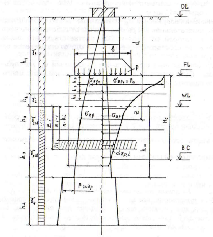
So, given that the method of layer-by-layer summation is the creation of several graphic studies of vertical stress in soils, then it is time to create them to calculate the permissible load on the soil.
On the surface of the earth σzg = 0, but at a depth of 1.8 meters (sole level), σzg 0 = γ1d = 18.7Κ · 1.8 = 33.66 kPa.
Now you need to calculate the ordinates of the vertical stress diagram at the joints of several soil layers:
It is also worth considering that the second layer of soil is saturated with water, so you cannot do without calculating the permissible pressure of the water column:

Ysb2 = (Ys2-Yw) / (1 + e2) = (26.6 -10.0) / (+ 0.60 1) = 10, 38kPa
Now attention. The example clearly states that the third soil layer takes on not only the pressure of the two upper layers, but also the water column, so these parameters cannot be neglected.
Thus, the stress along the base of the foundation will be calculated using the formula:

Additional pressure under the sole:

Further, all the parameters of the voltage studies must be selected from the calculation tables of SNiP. As a result, it turns out that the sediment S1 the first layer of sand will be:

Coarser sand draft:

Loam:
The total foundation settlement, calculated by the layer-by-layer summation method, will be:
According to the parameters specified in SNiP 2.02.01-83 * for structures erected on strip foundations, taking into account the indicated types of soils, the shrinkage parameter corresponds to the norm.
Nuances of calculating the pile foundation
Some features of the influence of the load exist for the pile foundation. Therefore, consider an example of calculation.
The main indicators that appear in the calculations:
- Pile radius.
- Length.
- Quantity.
- The distance at which adjacent elements are placed.
This example provides for simplified calculations.
Let's start by asking what the radius of the screw piles should be:
- radius 28.5 mm suitable for fencing;
- piles with a radius of 38 mm have a bearing capacity of up to 3 tons. They are used for laying the foundation for light buildings;
- 44.5 mm - piles, which are used for one-story buildings, frame houses, etc. Carrying capacity up to 5 tons;
- with a radius of 54 mm can be used for laying both one-story and two-story lightweight buildings. Able to withstand the effects of a load of 7 tons.
The distance between the piles also depends on the expected load. If aerated concrete or cinder blocks are used to build a building, then the step is 2 m, for lighter frame structures, no more than 3 m.
Calculation of the foundation settlement
There are several ways to calculate the settlement of the foundation. The main and most proven method for determining the final, total settlement is the method of summing the settlement of individual layers. For each of the layers, it is necessary to determine its own value of the degree of deformation. The layers should be considered within a certain soil thickness - in the core, and deformations that occur below this soil level can be excluded. The method of summing the sediment of individual layers can be used to determine any sediment.
The settlement can also be calculated using the equivalent layer method, which allows to determine the settlement taking into account the limited lateral expansion. An equivalent layer is a soil thickness that, under conditions of the impossibility of lateral expansion (when the entire surface is loaded with a continuous load), gives a settlement that is equal in size to the settlement of a foundation, which has limited dimensions under a load of the same intensity. That is, in this case, the spatial problem of calculating the settlement can be replaced by a one-dimensional one.
Calculation of the slump of the strip foundation
In addition to the layer-by-layer stacking method, there are various methods for determining the amount of building subsidence. Under the conditions of a detached structure, taking into account the resistance of the soil foundation and other forces, only the use of the layer-by-layer summation method will be the most correct calculation.
The method is based on creating stress plots in multilayer soil along each vertical axis.
 Calculation schemes for the method of adding the shrinkage of soil layers
The determination of the slump of the strip foundation is carried out in order to:
- determine the size of the slump of a monolithic tape with other bases attached;
- perform an accurate calculation of the settlement of the base of a building erected from different materials;
- determine the sedimentary nature and physical properties of the foundation of the building, which are associated with a change in the deformation index as the depth of the foundation increases.
This calculation methodology determines the base indicators for each combination of vertical axes, excluding angular variables, using peripheral values and a central indicator. This can be done when uniform structural soil layers are located along the perimeter of the base of the structure.
 Scheme for plotting stress by groups of vertical axes
Designations according to SNiP 2.02.01-83:
- S is the settlement index;
- zn is the average value of the stress along the vertical axis in the "n" layer;
- hn, En - compression thickness and deformation index of the layer "n";
- n is the specific gravity of the soil in "n";
- hn - layer height "n";
- b = 0.8 - constant coefficient.
The width of the strip monolithic foundation is 1200 mm (b), the depth of the foundation will be 1800 mm (d).
Video "Calculation of soil resistance":
An example of determining the amount of settlement of a strip foundation
The total load from the weight of the building on the soil will be 285,000 kg • m − 1 • s − 2. For each layer, the following values are noted:
- The upper layer is dry soil (fine sand, with porosity indices e1 = 0.65; density y1 = 18.70 kN / m³, compression index E1 = 14,400,000 kg • m − 1s − 2).
- The middle layer is wet coarse sand with the corresponding indicators: e2= 0.60, γ2 = 19.20 kN / m³; E2 = 18,600,000 kg • m − 1s − 2.
- The lower soil layer is loam with the corresponding values: e3 = 0.180; y3 = 18.50 kN / m³; E3 = 15300000 kg • m − 1s − 2.
 Ground layers with different shrinkage rates
The results of soil studies were taken from the local geological and geodetic administration. Groundwater in the development area is 3800 mm from the ground surface. the depth of the groundwater of this magnitude does not matter even for the buried foundation of the building. In this case, the impact of groundwater on the settlement of the building is considered scanty, that is, practically none.
To draw a diagram of diagrams and calculate critical loads on the soil, actions are performed in accordance with SNiP 2.02.01-83.
As a result, the following indicators are obtained for each soil layer: S1 = 11.5 mm; S2 = 13.7mm; S3 = 1.6 mm.
The total subsidence of the building base will be:
S = S1 + S2 + S3 = 11.5 + 13.7 + 1.6 = 26.8 mm.
Calculation of the settlement of the pile foundation
The settlement of the pile foundation is determined by the method of layer-by-layer summation.
 View of the pile foundation of the building
A full calculation of the settlement of the pile foundation is carried out by the design organization over the course of several days to 2 weeks. Designers use special computer programs. It is almost impossible for a person who does not have special education to do this on their own.
It is possible to calculate the settlement of the pile foundation of a small private house in a simplified way, which is within the power of every developer.
Using the layouts of various types of piles and design formulas specified in SP 24.13330.2011, it is possible to determine both the amount of settlement of a single pile and the degree of subsidence of the entire pile field.
Various methods are used for determining the settlement values of different types of foundations, mainly for large industrial and civil facilities.
Features of calculating the load from the type of foundation
After deciding on the depth of the foundation, it is necessary to calculate its width and other parameters depending on its type. Before calculating the load on the foundation, we determine the depth of its foundation, taking into account the type of soil. After that, we try to determine the rest of the parameters. To do this, we collect loads:
- materials from which the walls will be erected;
- wooden structures, rafters, beams;
- materials used for the roof;
- the estimated weight of furniture and people who will live in the house.
Having determined all the components, it is necessary to calculate the amount of material and its weight. The results obtained are multiplied by the static load reliability index. It is different for each species:
- metal - 1.05;
- tree - 1.1;
- factory reinforced concrete - 1.2;
- self-made reinforced concrete - 1.3;
- payloads - 1.2;
- snow load - 1.4.
A few tips for laying the foundation
Many, especially novice builders, trying to improve the quality and reliability of the foundation, make some mistakes. Let's try to point out the main nuances:
By increasing the height of the base strip, a high degree of rigidity can be achieved. But this indicator does not always lead to positive results and reduces the impact of loads on it. It is necessary to carry out the reinforcement of the foundations, which increases the degree of stress. The base must be made flexible, thereby reducing the stiffness factor.
It is difficult to calculate the deformations due to loading, which are caused by factors such as frost heaving or the influence of groundwater. They can change over time. Therefore, it is best to contact a specialist to determine the type of soil and the influence of climatic conditions.
To prevent the occurrence of deformations of the base, attention should be paid to measures to strengthen both the foundation itself and the basement with walls.
To reduce the impact on the base of frost in winter and demi-season moisture, it is recommended to carry out a number of measures for insulation and waterproofing. In the event that they are planned, then this factor must be taken into account when calculating the load.
If you started this important task yourself, then you can use special programs such as Lear. It is a computer program that allows you to carry out construction calculations. It is only necessary to enter all the parameters correctly, and the technique will calculate and give the result: calculation of the foundation with a horizontal load, the area of the sole and the thickness of the cushion. Plus, it's a great test of your own calculations. Don't forget about online calculators.
Maximum permissible settlement of foundations
To date, there is no convincingly substantiated standard value of the maximum permissible additional settlement of buildings. Normally, regulations do not differentiate between the initial, obtained during construction, and the additional draft. According to the documents, the maximum average draft of a brick building is approximately 10-12 cm.
It is worth noting that the initial settlement of the foundation on a homogeneous soil base is uniform over the building spot, therefore, even with a large permissible average settlement (10-12 cm), the requirements for uneven settlement are also satisfied. And, as you know, the result of unevenness are distortions of the building and the occurrence of cracks.
According to the standards, the maximum permissible draft for buildings of the 1st category of technical condition is 5 cm, and for buildings of the 2nd and 3rd categories, which already have deformations - 3 and 2 cm.
As observations show, brick buildings of the 1st and 2nd category of condition with a local additional draft of 5 cm can receive serious damage. Through cracks will form in the walls, and when a vertical crack occurs, its opening is comparable to the amount of settlement. The displacement of prefabricated floor slabs in this case along the support areas is very close to the limiting one. In this case, the renovation of the building will require the eviction of the tenants, selective reinforcement of the structure and restoration of the interior and exterior decor. With precipitation of 3 and 2 cm, smaller repairs will be required. So, can a foundation draft of 2-5 cm be considered permissible? Of course, if the absence of collapse of structures is taken as the criterion of admissibility, and it is impossible, if the criterion of admissibility is the absence of damage that requires repair.
Initial data
Help and accepted symbols (click to open / close)
The following units of measurement are accepted in the calculations: tons, meters.
According to SP 22.13330.2011, the coefficient to natural pressure for determining the depth of the compressive strata is taken equal to 0.5. Correction of the coefficient to a value of 0.2 is performed automatically in the case when the lower boundary of the compressible stratum is in the soil layer with the modulus of deformation E 2
If within the depth of the compressible strata there is a layer of soil with a modulus of deformation E> 10000 t / m2, then it is taken up to the roof of this soil
When indicating that the layer is watered, the next layer without water is taken by the aquiclude to obtain the corresponding jump on the natural pressure plot. In this case, the designation of the layer in the form of a confining layer in the pivot table is not displayed without detailed breakdown.
Legend:
Ei - modulus of deformation of the constituent soil layer, t / m2
kE, e, i - the multiplier to the deformation modulus for the transition to the deformation modulus along the secondary branch (for structures with a normal level of responsibility, it is allowed to be taken equal to 5.0)
γi - specific gravity of soil, t / m3
γs, i - specific gravity of soil particles, t / m3
hi - thickness of the groove layer, m
e - coefficient of porosity
The data for the first layer is given as an example.
Design load on the base Fz (T):
Coefficient to natural pressure for determining the depth of the compressive strata (from 0.2 to 1.0, according to the joint venture it is recommended to take 0.5):
Additional pressure to the natural pressure plot (t / m2):
Foundation form:
- Circle
- Rectangular
Foundation depth (m):
Foundation width or diameter (m):
Foundation length (m, only for rectangular type):
Number of soil layers (n ≤ 10):
Reasons for the appearance of foundation settlement
The composition of the soil is one of the most important reasons due to which the sediment of the base of the house occurs. The soil is divided into types and each has its own strength. The most durable types of soil cover are rocky soil and dispersed soil. In another way, these soils are called incoherent, since they will not retain moisture in themselves.
The first type of soil is based on monoliths, and the second type consists of mineral grains of various sizes.But there are connected types of soil, they absorb and retain moisture, therefore, the main component of these types of soil cover is clay, due to which the soil layer acquires the property of mobility and deformation. In the cold season, the moisture contained in these types of soil freezes and the soil layer expands. The first reason is a cohesive layer of soil. The second reason is the design features of the foundation of the house. The third reason is the incorrectly distributed pressure of the walls on the foundation. When building a house, all these factors should be taken into account so as not to face this problem in the future.
Data on the composition of the soil massif of the base
Layer 1
Ei (t / m2):
kE, e, i:
γi (t / m3):
hi (m):
γs, i (t / m3):
e:
Availability of water: Without waterWater-saturatedWaterproof
Layer 2
Ei (t / m2):
kE, e, i:
γi (t / m3):
hi (m):
γs, i (t / m3):
e:
Availability of water: Without waterWater-saturatedWaterproof
Layer 3
Ei (t / m2):
kE, e, i:
γi (t / m3):
hi (m):
γs, i (t / m3):
e:
Availability of water: Without waterWater-saturatedWaterproof
Layer 4
Ei (t / m2):
kE, e, i:
γi (t / m3):
hi (m):
γs, i (t / m3):
e:
Availability of water: Without waterWater-saturatedWaterproof
Layer 5
Ei (t / m2):
kE, e, i:
γi (t / m3):
hi (m):
γs, i (t / m3):
e:
Availability of water: Without waterWater-saturatedWaterproof
Layer 6
Ei (t / m2):
kE, e, i:
γi (t / m3):
hi (m):
γs, i (t / m3):
e:
Availability of water: Without waterWater-saturatedWaterproof
Bed 7
Ei (t / m2):
kE, e, i:
γi (t / m3):
hi (m):
γs, i (t / m3):
e:
Availability of water: Without waterWater-saturatedWaterproof
Bed 8
Ei (t / m2):
kE, e, i:
γi (t / m3):
hi (m):
γs, i (t / m3):
e:
Availability of water: Without waterWater-saturatedWaterproof
Bed 9
Ei (t / m2):
kE, e, i:
γi (t / m3):
hi (m):
γs, i (t / m3):
e:
Availability of water: Without waterWater-saturatedWaterproof
Bed 10
Ei (t / m2):
kE, e, i:
γi (t / m3):
hi (m):
γs, i (t / m3):
e:
Availability of water: Without waterWater-saturatedWaterproof
Features of calculating the load on the MZGF
The shallow foundation has its own characteristics in calculations. It is necessary to correctly determine what loads a given base can withstand. The calculation of a shallow strip foundation is based on certain rules:
- it is necessary to determine the depth of laying based on the degree of influence of geological factors, that is, the depth of soil freezing and the formation of groundwater;
- above the ground, the maximum permissible height of the tape is 4 widths, but at the same time it does not exceed the depth of the base;
- correctly calculate the width of the sole. For this, the formula D = g / R is used. D is the width of the base, g is the collection of loads on the strip foundation, R is the resistance of the soil, the indicators of which are different for each type of soil.
- then we proceed to calculating the thickness of the pillow for a shallow foundation. This indicator is influenced by the degree of soil strength. Formula for calculating t = 2.5 * D * (1-1.2 * R * D / g). For unstable and problematic soils, it is better to use the following formula t = (A-C * D * g) / (1-0.4 * C * W * (g / D)). A, C, W - coefficients that can be determined from the tables below.

The following table gives the value of the W coefficient. The numerator indicates the value for a shallow foundation of 30 cm, in the denominator - for foundations that are not buried.


