2. REQUIREMENTS FOR SURVEYS
2.1. The volume and scope of survey work for objects designed on pile foundations with a reduced volume of pile underfilling (or with its complete exception) should guarantee an increased detail in assessing the variability of soil properties (in plan and in depth). For this, it is recommended to increase the proportion of high-speed methods for determining the resistance of piles (express methods) and, accordingly, increase the number of points for site inspection. It is recommended to use static sounding with high-performance installations of the C-832M type as the main express method. Recommended sounding volumes are given in the recommended appendix.
2.2. Sounding points should evenly cover the entire territory of the projected building or structure. If an increased heterogeneity of the soil is detected, the "grid" of sounding points should be thickened throughout the surveyed territory. The frequency of location of sounding points in the plan depends on the complexity of soil conditions and on average should be taken at the rate of 1 point per 50 ... 100 m. In the case of a group arrangement of objects, it is recommended to evenly place sounding points throughout the entire site, covering both the territory of buildings and intermediate zones.
2.3. When performing probing and calculating the bearing capacity of piles, the existing normative and recommendatory documents should be used, carrying out additional calculations in accordance with these Recommendations.
7. ORGANIZATION AND TECHNOLOGY OF PILING
7.1. Driving of piles with the accuracy specified in the project is carried out according to the traditional technology with ensuring strict control over the position of the piles during the entire driving process: at the time of installing the pile at the driving point, ensuring the verticality of the pile during installation and during driving, ensuring the alignment of the pile and the hammer, instrumental control beyond the immersion level.
7.2. Depending on the requirements for the accuracy of pile driving in the plan, it is recommended to use the following pile driving methods;
- immersion of piles without guiding devices;
- immersion of piles using metal conductors;
- immersion of piles into the holes of concrete and reinforced concrete conductors-elements of the structure.
The accuracy of pile driving in the plan, provided by each method, is given in Table 4 (with a standard accuracy of ± 6 cm).
Table 4
|
Pile driving method |
The deviation of the piles in the plan, cm |
|
Without guiding devices |
±6 |
|
Using metal conductors |
±5 |
|
In holes in concrete and reinforced concrete conductors-structural elements |
±3 |
7.3. immersion of the pile with a given accuracy in the plan is achieved if the following basic requirements are met:
- installation of the pile on the driving point with an accuracy of ± Icm;
- alignment of the verticality of the pile before driving, driving the pile to a depth of 0.5 m and re-alignment of the verticality of the pile ;,
- ensuring the alignment of the hammer-pile system during the driving process to the full depth;
- use of piles with a blunt bottom end.
Detailed technology of work, used devices and devices are given in.
7.4. Control of the design level of driving should be carried out with the help of sighting devices, along the lighthouse piles, with the help of levels and level gauges. The first two methods provide, with a certain skill of the pile driver, the pile driving accuracy of ± 4 cm from the design mark, with the help of instruments ± 2 si. It should be borne in mind that the diesel hammer, after stopping the fuel supply, produces 1 - 3 blows on the pile, depending on its technical condition. Therefore, the fuel supply should be stopped in advance, otherwise breaking the piles in soft soils can be 10 cm or more.The control technology is given in.
Table 5
|
Pile type and location |
Permissible deviations of pile axes in plan |
|
Driven piles of square and rectangular cross-sections, hollow circular cross-section with a diameter of up to 0.5 m: |
|
|
a) single-row arrangement of piles: |
|
|
across the axis of the pile row |
0.2d |
|
along the axis of the pile row |
0.3d |
|
b) bushes and belts with piles in two or three rows for the outermost piles across the pile row |
0.2d |
|
for the rest of the piles and for the extreme piles along the pile row |
0.3d |
|
c) continuous pile field under the entire building |
|
|
for extreme piles |
0.2d |
|
for medium piles |
0.4d |
|
d) single piles for a column |
5 cm |
|
e) pile-columns |
3 cm |
Notes: 1. The number of piles with the maximum permissible deviations from the design position should not exceed 25% of the total number of piles with a strip arrangement. The question of using piles with deviations above the permissible ones is established by the design organization.
2. d- diameter of a round, square side or the smaller side of a rectangular pile.
7.5. In the process of driving the piles, the master must maintain documentation in accordance with SNiP 3.02.01-83
Particular attention should be paid to determining the residual failure at the end of the pile sinking. The deviation of the value of the control failure from the actual one obtained during dynamic tests should not be more than -20%
The technology, instruments and equipment for determining the residual failure of the pile are given in.
7.6. Deviations of driven piles from the design position should not exceed the values given in Table 5 (deviations in the plan according to SNiP 3.02.01-83) and Table 6 (deviations from the design mark) or the values specified in the project with appropriate justification.
Table 6
|
View of the pile foundation |
The greatest permissible deviations of the pile heads from the design mark, cm |
|
Foundation With monolithic grillages |
±5 |
|
Foundation with prefabricated slab grillage (platform joint) |
±1 |
|
Gridless foundation with prefabricated top |
-5 |
|
Column piles |
-3 |
7.7. Acceptance of works on the construction of pile foundations is carried out in accordance with the documentation for SNiP 3.02.01-83.
2.3. Combined pile-slab foundations (KSP)
2.3.1.
Combined pile-slab foundations (KSP) are used for multi-storey
heavy buildings, the construction of which is planned on sites where from the surface
soils of medium strength and slab foundation lie, even with sufficient
bearing capacity of the soil, does not pass through deformations.
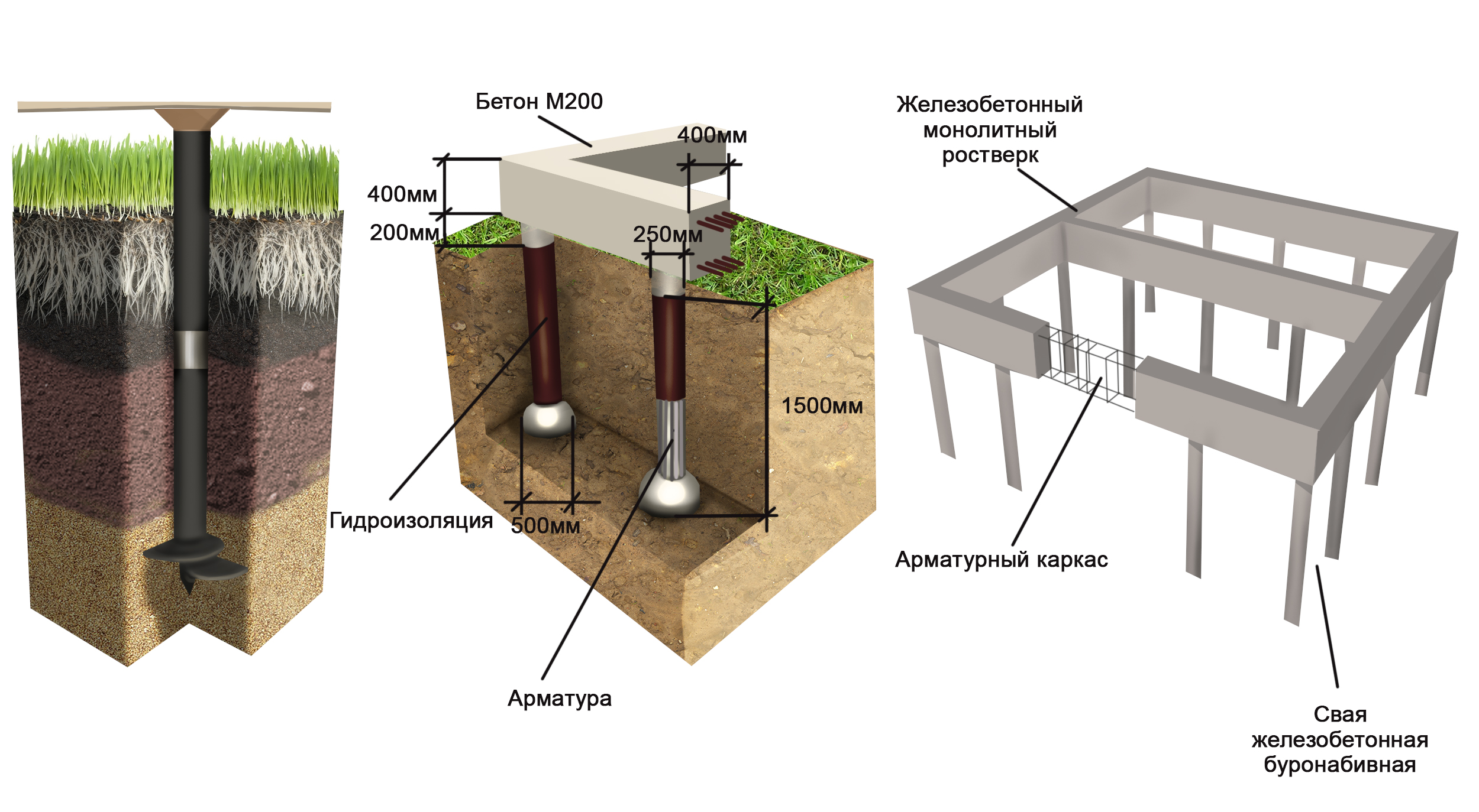
2.3.2. For PCB
foundations, bored piles with a diameter of 800 - 1200 mm and a length of up to
the size, width of the building, constructed according to the technology provided for in clause 2.5a) of SNiP 2.02.03-85,
or driven reinforced concrete piles, solid, square section with a transverse
barrel reinforcement with dimensions 35´35 or 40´40 cm in accordance with GOST 19804.1-79 *.
2.3.3.
According to soil conditions and the structure of the foundation of the pile in this type of foundation
must work as hanging, and therefore they are located under the foundation
slab on a grid with distances between the axes of piles 5-7 diameters (transverse
sizes).
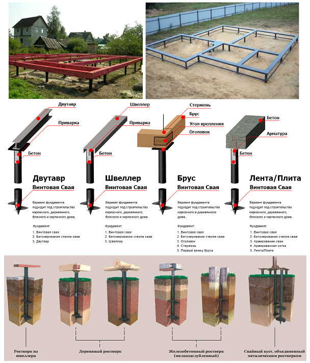
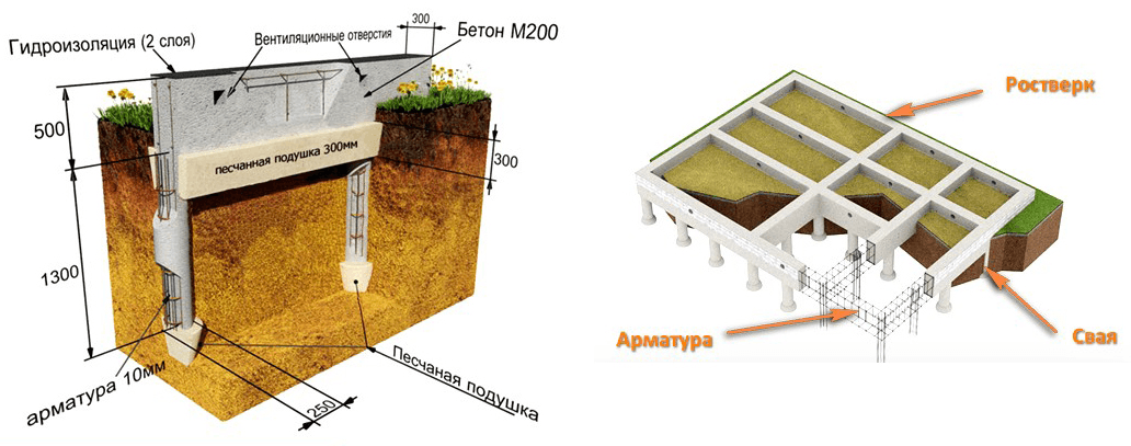
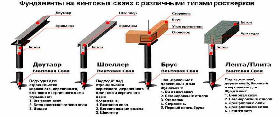
2.1. Structures made of screwed piles
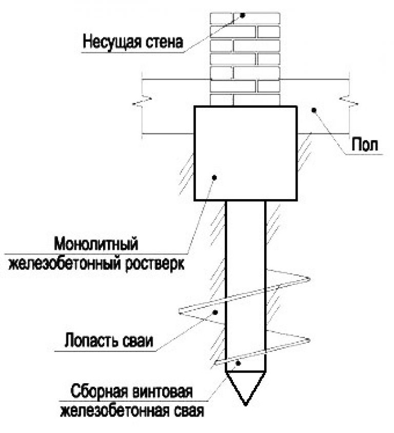
2.1.1. Screw-type
piles are used in non-rocky soils for the construction of load-bearing or
combined (bearing and enclosing) foundation structures and
manufactured according to the RF patent "Method of erecting piles in the ground"
(patent N 2073084).
2.1.2.
The screw-on pile () consists of a metal
pipe (1), cruciform tip (2) and spiral winding (3),
ensuring the immersion of the pile by rotating it in combination with indentation.
2.1.3.
Metal pipes used for the manufacture of screwed piles,
can have an outer diameter from 100 to 800 mm and a length of up to 12 m. Wall thickness
pipes must be at least 6 mm and meet the requirements for strength and
durability.
Rice.
2.1. Diagram of a screwed pile
2.1.4.
The cruciform tip is made in two metal pointed
plates with a thickness of 8 mm, welded in the form of a cross between themselves. Depending on the
technology of the device of screw-in piles, the tip can be removable and
left in the ground after the pile is immersed; up to the design mark or deaf,
welded to a round plate with a thickness of at least 6 mm, covering the lower end
piles. The tip angle is 60 °.
2.1.5.
Spiral Winding is a continuous metal bar
triangular, square or circular cross-section (for example, reinforcement) with a width of =
(0.04¸0.06) d,
welded to a metal pipe with a pitch a = (0.5 - 1.0) d, where d is
outer diameter of the pipe.
2.1.6. At
using a removable tip, the walls of a screwed pile are performed
the role of inventory casing and piling technology is similar
technology used in the manufacture of bored piles of the BSI type.
2.1.7. The main
the field of application of foundation structures made of screwed piles -
construction and reconstruction of buildings and structures, near existing buildings and
structures, when the immersion of driven and vibrating piles can cause
unacceptable dynamic effects on nearby buildings and structures and their
foundations, and the device of bored piles - unacceptable unloading and
loosening of soils when driving wells.
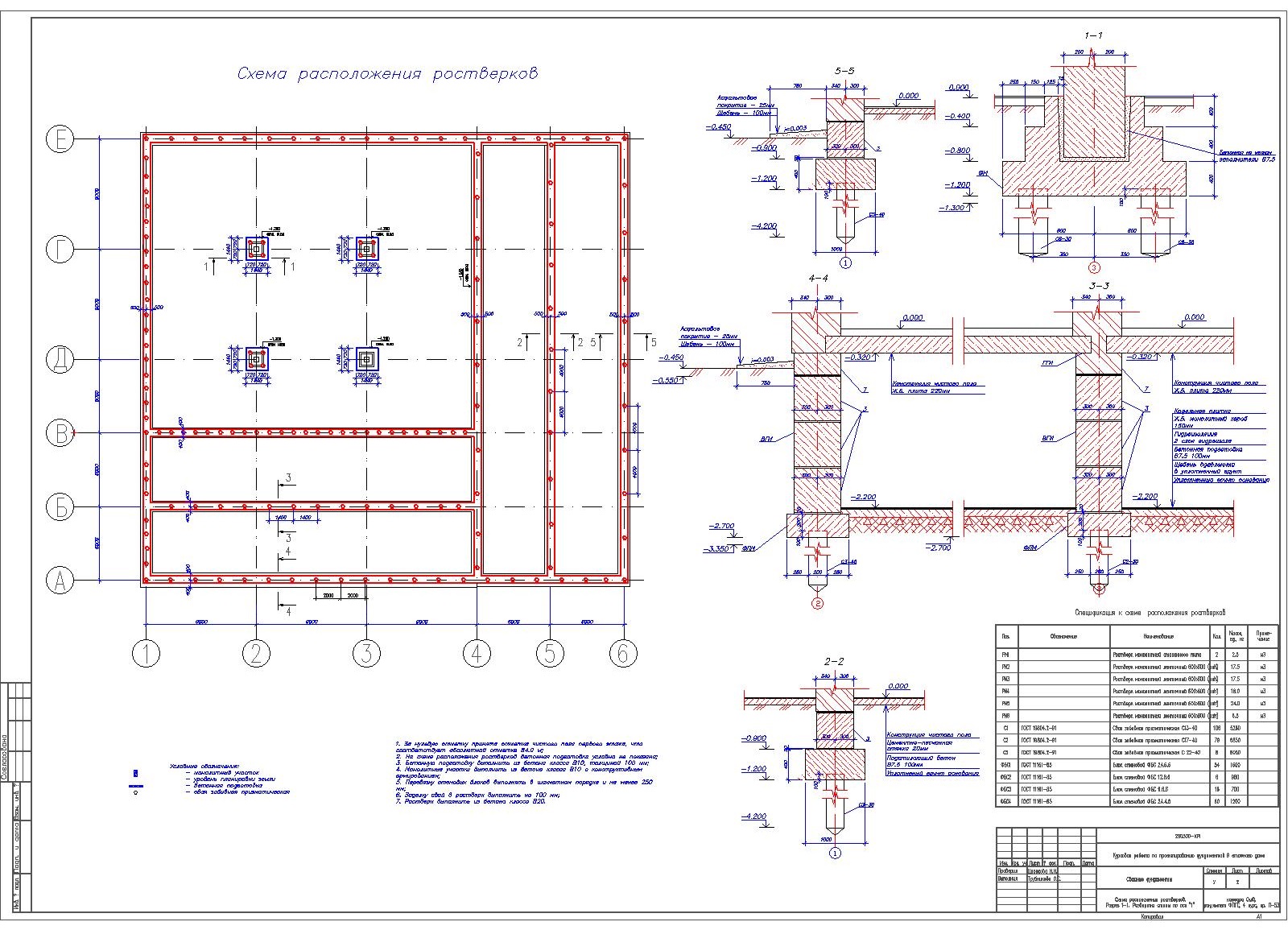
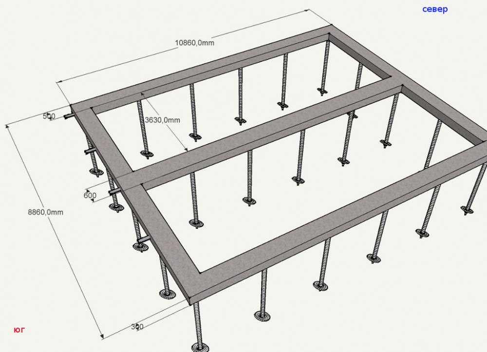
Self-verification of the correctness of the project
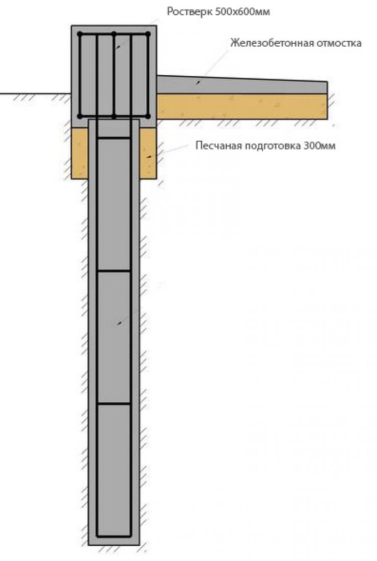
 Sketch indicating the determination of the dimensions of the foundation piles in all parameters
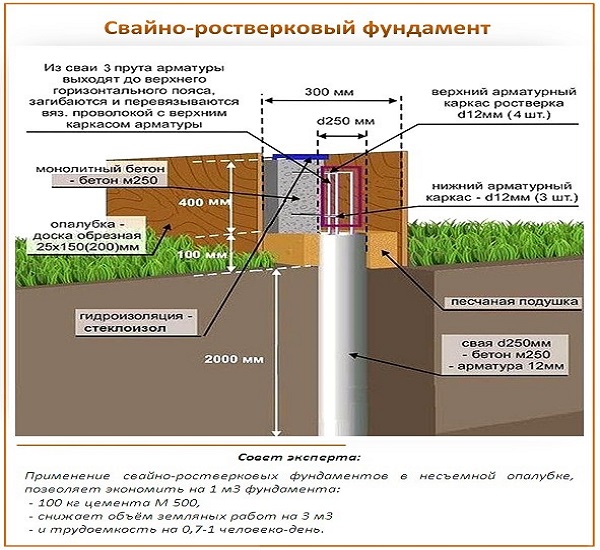
In calculating the permissible soil load, there is always such a factor as the bearing capacity of screw piles, and it depends on the type of soil. For example, the SVS 108/2500 pile can withstand up to 17 tf. Therefore, all bases, depending on the existing loads, are divided into groups by the project:
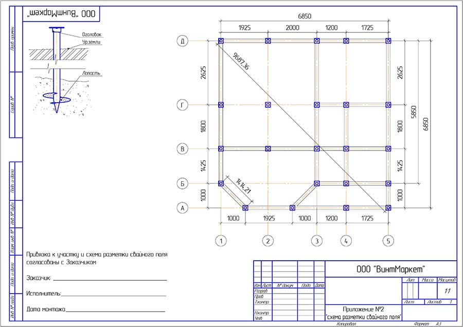
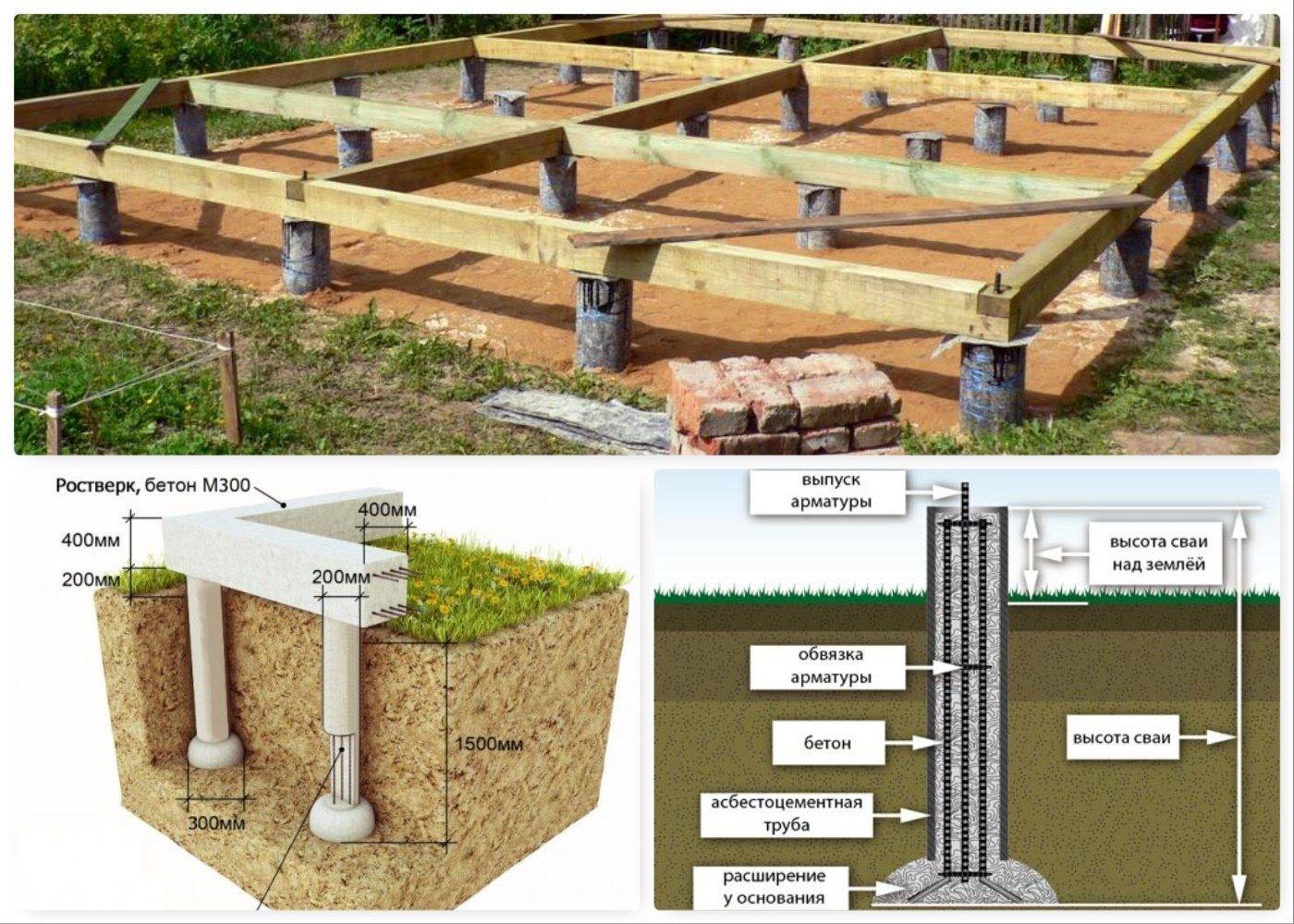
- Single piles - for small compact buildings, installed at the intersection of load-bearing walls.
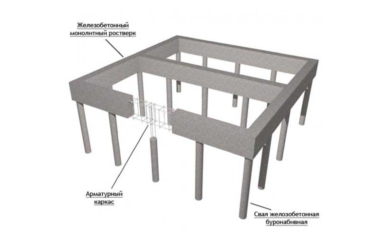
- Pile belts are installed at a certain design interval under the load-bearing walls in order to transfer the loads distributed along the length to the ground. There may be several such rows, all supports are connected to each other by grillages or internal reinforcement.
- Bushes are structures of a rectangular, square or round shape, they are installed under the columns, reinforced as a whole. They are used to transfer loads from large, massive, low-rise industrial buildings.
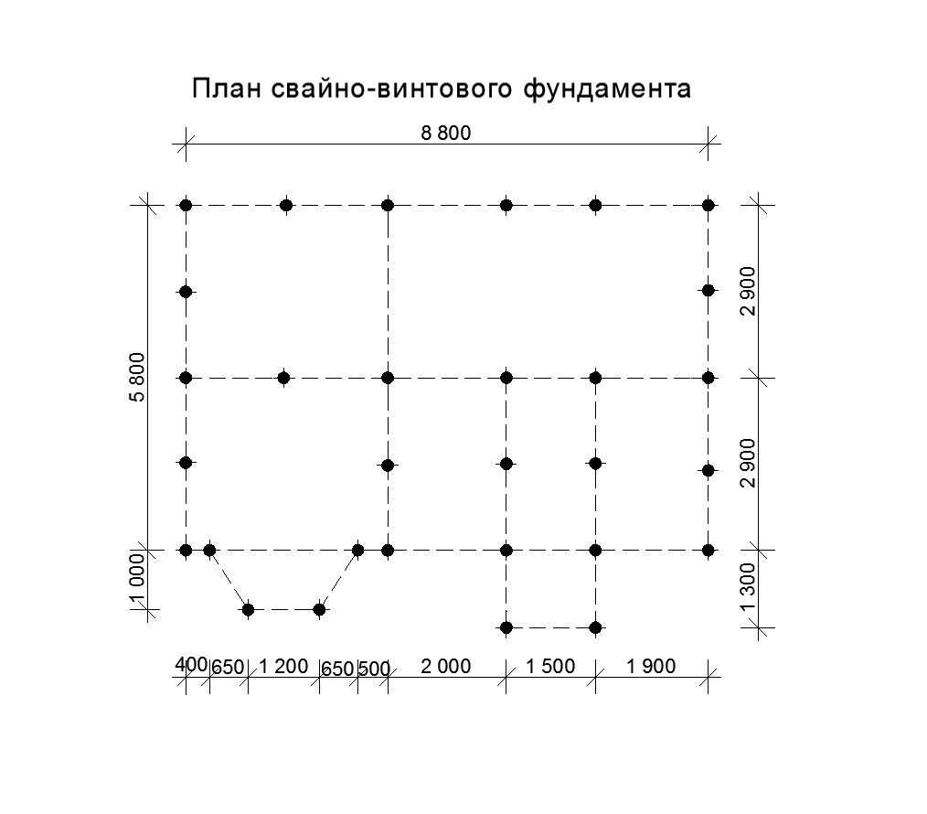
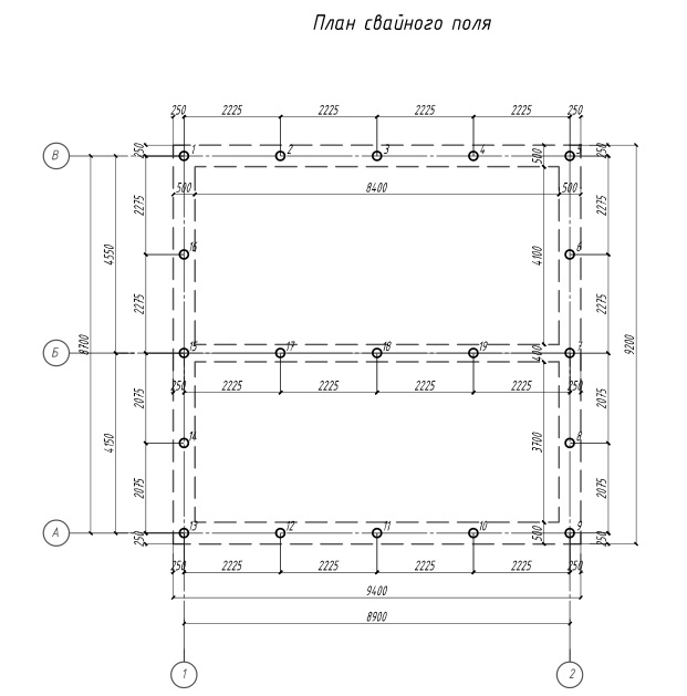
- The pile field is used in the construction of heavy structures, the piles are evenly spaced under the base of the building, united by a single grillage and aligned horizontally.
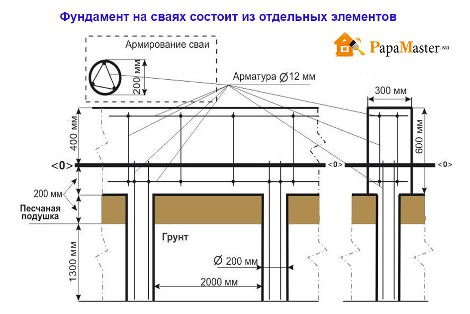
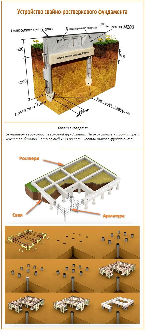
In some projects, a section may be provided for describing the type of grillage, its structure and the method of reinforcement.
The number of piles and their dimensions, as well as the material of the products, are determined based on the calculation of the maximum resistance of the pile material, as well as the bearing capacity of the soil. Such requirements are described in detail in SP 50-102-2003, there is also data on the structure of the metal and its strength testing.
Also, the project provides for the calculation of mating - this is the joint effect of a stand-alone support on another due to the uniform transfer of loads through the grillage. The calculation is rather complicated, it involves the use of the resistance of the reinforcement metal, the material of the supports and the horizontal mobility of the grillage.
The choice of the design and dimensions of piles is always carried out taking into account the values and directions of the impact of loads on the foundations, including technological ones, as well as the technology of building construction. Thus, only a professional can develop a detailed design of a pile foundation, but the result will be high-quality construction documentation with a detailed description of each stage of construction work.
Application
TsNIIEPselstroy has developed a device for stamping out pyramidal pits. The device allows:
reduce energy consumption;
improve the quality of the seal;
to minimize the costs of reinforcement;
reduce the cost of erecting pile foundations. The device is simple to manufacture and reliable in operation.
Removing the device from the ground
The sequence of the construction of foundations using the proposed device:
construction site layout;
breakdown of axes and pile field;
immersion in the ground of the device using a pile driving unit to the design level;
removing the device from the ground using a pile driving unit, while the side walls of the device are folded, reducing the resistance of the soil to pulling out.
In fig. shows a diagram of the device when it is removed from the ground.
Construction using foundations in stamped cavities makes it possible to exclude excavation and formwork, reduce concrete consumption by 30 ... 70%, estimated cost and labor costs - by 1.5 ... 3 times.
TsNIIEPselstroy provides technical assistance in the implementation of pyramidal piles in a stamped bed, provides consultations, sends design documentation, and supplies equipment to the customer.
FOREWORD
Pyramidal and short bored piles are effective zero-cycle structures for low-rise agro-industrial complex. The use of foundations from short piles in frost-hazardous, heaving soils is limited by the current regulatory documents. Fulfillment of the requirements of the norms, according to which even minor movements of piles caused by soil heaving are not allowed, leads to an increase in their length, which sharply worsens the technical and economic indicators of pile foundations.
At the same time, the requirement of inadmissibility of pile buckling is not justified, since any building and structure is able to withstand some uneven deformations of the foundations. The use of foundations from short piles is based on a fundamentally new approach to their design, which is based on the calculation of heaving deformations. A similar approach was used in the design of shallow foundations. Positive experience in the construction and operation of buildings with shallow foundations about its legality.
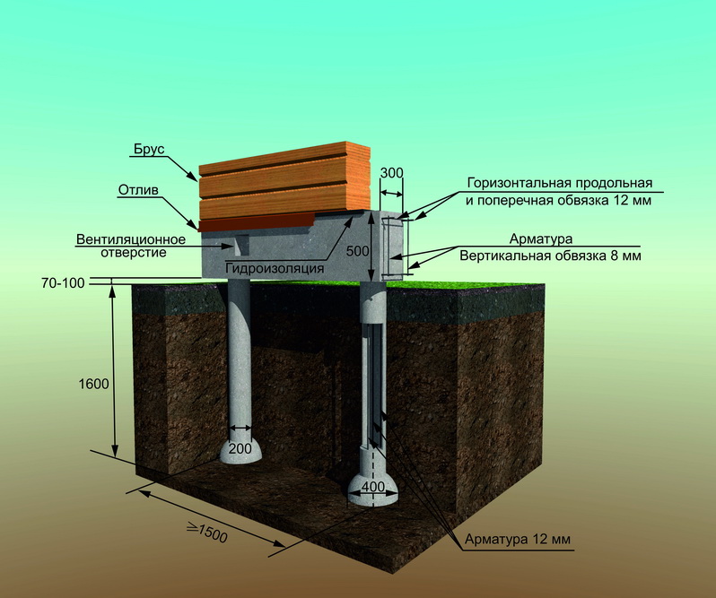
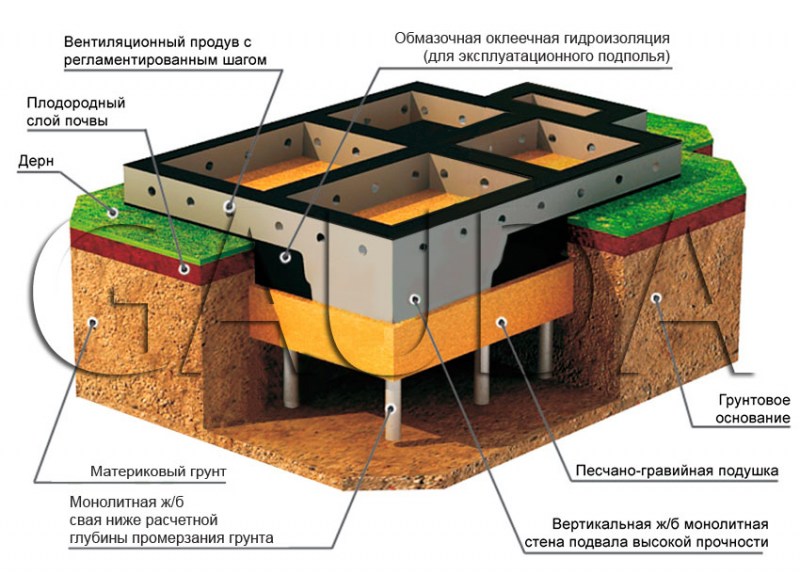
When constructing foundations from short piles, the same principle is used as when constructing shallow columnar foundations: foundation beams, basement panels are combined into a single system, forming a fairly rigid horizontal frame.
Such a system redistributes the uneven movements of individual piles, levels them, which ultimately reduces the relative deformations of foundations and overground structures of buildings.
When designing pile foundations, as well as shallow ones, the requirement is put forward that the absolute and relative heaving deformations do not exceed the maximum permissible. The latter depend on the design features of buildings and are regulated by VSN 29-85.
For pile foundations, in the bearing capacity of which a large specific weight is the bearing capacity of the lateral surface, it is necessary to fulfill the condition of the absence of residual heaving deformations.
It is necessary that when the soil thaws, the piles return to their original position, i.e. their precipitation should be no less than the rises caused by the heaving forces.
Thus, when designing short piles, their geometric dimensions should provide the necessary bearing capacity, and the acting load should ensure regulated lifting and return of the pile after thawing of the soil to its original position.
In recent years, TsNIIEPselstroy has carried out extensive studies of the interaction of pile foundations with heaving soils. Tests of foundations were carried out on sites formed by soils with varying degrees of heaving. Based on the research results, the technical feasibility of using short piles in heaving soils has been substantiated, and methods for calculating them based on heaving deformations have been developed.
The provisions of these "Recommendations" have been tested in the design and construction of pile foundations for manor-type residential buildings. At present, more than 600 houses have been built on heaving soils using such foundations in the Omsk, Perm, Saratov, Yaroslavl and other regions. Instrumental observations are being carried out for many of these buildings, which testify to the reliable operation of foundations from short piles. At the same time, the use of such foundations instead of strip made of prefabricated blocks, laid below the depth of soil freezing, made it possible to reduce concrete consumption by 30 ... 60%, the volume of earthworks - by 80 ... 90%, labor costs - by 1.5 ... 2 times.
"Recommendations" were developed by V.S. Sazhin and V. Ya. Shishkin. Engineers L.M. Zarbuev, K.Sh. Pogosyan, T.A. Prikazchikova (TsNIIEPselstroy), Candidate of Technical Sciences A.G. Beirit, engineer A.P. Aydakov (Mosgiproniiselstroy) and candidate of technical sciences V.N. Zekin (Perm State Agricultural Institute).
The "Recommendations" apply to the design of foundations from short (up to 4 m long) pyramidal and bored piles of low-rise (up to two storeys inclusive) rural buildings built on weak and medium-heaped soils with a standard freezing depth of no more than 1.7 m.
At the same time, the requirements provided for by SNiP 2.02.01-83 with amendments to it No. 211 and other relevant all-Union documents must be observed.
3. ESTIMATION OF THE FUNCTIONALITY OF DESIGNING FOUNDATIONS WITH IMMERSION OF THE PILES TO A PERIODED MARK
3.1. It is recommended to evaluate the feasibility of using pile foundations with pile driving to a given elevation at the design stage, based on survey data and information about available pile-driving mechanisms.
3.2 Assessment of the technical and economic feasibility of using pile foundations with pile driving to a given elevation can be carried out by means of special calculations or without them based on the analysis of engineering and geological sections and the features of the designed structures. The methodology for such an assessment is recommended to be adopted on the basis of clauses 3.3 ... 3.5.
3.3. The decision on the inexpediency of driving piles to a given elevation can be made without special calculations if there is a clearly defined bearing layer in the depth range under consideration in the form of a layer of coarse-grained or rocky rocks with an uneven or inclined roof. In this case, pile driving should be carried out until the specified failure, and the unfinished parts of the piles should be cut down.
3.4. Driving piles to the required depth is ensured if the following requirements are met:
- pile failure Swith the selected hammer in the area with the most durable soils, at least a predetermined value is expected S... For objects of mass construction, it is recommended to take S= 0.5 cm;
- the number of blows of the selected hammer does not exceed the critical value set depending on the impact resistance of the selected piles, the method for checking these conditions is given in.
3.5. In cases not covered in clause 3.2, it is recommended to make a simplified quantitative assessment of the material consumption of the following two options for foundations:
1) the piles are driven to different depths up to a given equal failure (on the assumption that this failure corresponds to the failure of the hammer's immersion capacity), the underloaded parts of the piles are cut down;
2) the piles are immersed to the same depth, corresponding to the minimum pile depth in the first option, so that the cutting of the pile is excluded.
It is recommended to evaluate the feasibility of these options on the basis of sounding data, using the simplified criterion given in clause 3.6.
3.6. The material consumption of a cluster or strip foundation with the immersion of the piles to a given level should be considered lower than the material consumption of the foundation with the immersion of the piles to failure, if the following condition is met:
where Fu.n- average (standard) resistance of piles in kN with immersion depth hin m;
h- the considered depth of immersion of the piles, conventionally taken as the depth corresponding to the second option in clause 3.5;
- a value reflecting the intensity of the increase in the average limiting resistance of the pile with increasing depth in m / kN (in practical calculations it is convenient to take the variability Fu.n. in the range from h before h+1 m);
V- the value taken with a low grillage equal to 0.8, for other pile structures - 0.6.
3.7. The assessment of the labor intensity of pile work should be made, taking approximately the labor costs for cutting each pile and removing its debris equal to the cost of driving it. The proportion of piles subjected to felling in such calculations can be taken equal to 70% of their total number.
3.8. The number of sections within which a single pile immersion depth is taken should be selected so that at each section the coefficient of variation of the ultimate pile resistance does not exceed 0.3.
3.9. The question of the use of pile foundations with the immersion of piles to a given level should be resolved together with the question of the expediency of certain pile structures. It is recommended to use foundations with piles immersed to a given elevation for buildings on pile-columns, with non-grouting pile foundations, with single-pile foundations in which shearing of piles causes difficulties (combined pile foundations, etc.).
3. Calculation of the foundations of pile foundations for the action of vertical loads
where N - design load transmitted to the pile;
Fd - the calculated bearing capacity of the pile on the ground;
- the coefficient of reliability, taken equal to 1.25, if the bearing capacity of the pile is determined based on the results of field tests with a static load or calculation for deformations.
where TO - coefficient of proportionality, equal to the ratio of the load on the pile heel to the total load at the maximum settlement of the pile S, taken equal to 8 cm: coefficient TO depends on the pile length ratio l to its diameter d and the consistency of soils. For soils of solid and semi-solid consistency at ld£ 3,75 TO = 0.45; at 3.75 ld£ 5 TO = 0.40; at 5 ld£ 7,5 TO = 0.37. For soils with a rigid-plastic consistency with the indicated ratios ld coefficient TO equal to 0.5, respectively; 0.45 and 0.40. For soils of soft plastic consistency - 0.55; 0.5 and 0.45;
- coefficient taking into account the increase in the settlement of the pile in time, taken equal to:
0.5 - for silty clay soils of solid consistency;
0.4 - for silty-clayey soils of semi-hard and refractory consistency;
0.3 - for silty clay soils of soft plastic consistency;
SAve Wed - the maximum permissible average settlement of foundations, taken for low-rise rural buildings, equal to 10 cm;
- the ultimate bearing capacity of the lateral surface of the bored pile, determined by the formula
where RWed - the average pressure at the contact of the lateral surface of the pile with the ground, equal to
(3.4)
where - the coefficient of lateral pressure of the concrete mixture is taken equal to 0.9;
- specific weight of concrete mix, kN / m3;
l - the length of the pile section, in which the pressure of the concrete mixture on the borehole walls increases linearly with depth, l = 2 m;
- relative shrinkage of concrete during hardening in contact with the ground: with a soil flow rate of £ 0.20JL = 3 10-4, for £ 0JL = 4 10-4, at JL = 5·10-4;
E, - the calculated modulus of deformation and Poisson's ratio of the soil, respectively.
Included in the formula () resistivity with1 and the angle of internal friction of the soil, taking into account its hardening during concreting of the pile, are equal: j1 = jI + (5 … 7)°; with1 = withInwhere jI, withI - design angle of internal friction and design cohesion of natural soil; n - coefficient taken equal to 1.8; 1.4; 1.3 and 1.2, respectively, for soils of hard, semi-hard, hard-plastic and soft-plastic consistency.
Note. In the case of heterogeneous soil within the pile length, the weighted average values of the characteristics used are introduced into the calculation.
3.3. The design bearing capacity of pyramidal piles and driven blocks is determined according to VSN 26-84 "Design and installation of pyramidal piles and driven blocks for low-rise rural buildings".