Foundation settlement
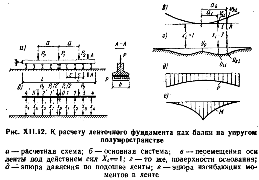
Another strictly standardized value when calculating a strip foundation is its draft. It is determined by the elementary summation method, for which data from the engineering survey report will again be needed.
The formula for determining the average settlement value according to the linear-deformable layer scheme (Appendix G SP 22.13330.2011).

Application diagram of the linear-deformable layer technique.
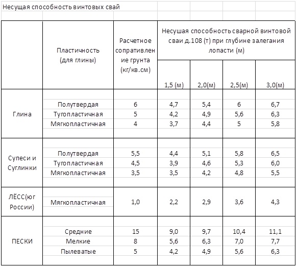
Based on the experience of construction and design, it is known that for engineering and geological conditions, characterized by the absence of soils with a deformation modulus of less than 10 MPa, weak underlying layers, macroporous IGE, a number of specific soils, that is, under relatively favorable conditions, the calculation of settlement does not lead to the need to increase the width of the base foundation after calculating the bearing capacity. The reserve for the design draft in relation to the maximum allowable is usually obtained several times. For more complex geological conditions, the calculation and design of the foundations should be carried out by a qualified specialist after conducting engineering surveys.
Calculation of the amount of concrete, wire and reinforcement
Having decided on the dimensions of the foundation, you need to calculate how much reinforcement, wire and concrete we need.
With the latter, everything is just simple. The volume of concrete is equal to the volume of the foundation, which we already found when we calculated the load on the ground.
But what kind of metal to use for reinforcement has not yet been decided. It all depends on the type of foundation.
Reinforcement in strip base
For this type of foundation, only two reinforcement belts and reinforcement with a thickness of up to 12 mm are used. Horizontal longitudinal reinforcement bars are subject to greater stress than vertical or transverse ones.
Therefore, ribbed reinforcement is placed horizontally, and smooth reinforcement vertically.
The length of the ribbed reinforcement is easy to calculate if you multiply the total length of the base by the number of rows of bars. If the foundation is narrow (40 cm), two longitudinal bars for each chord are enough. Otherwise, the amount of reinforcement in the belt will have to be increased.
Transverse rods are mounted every 0.5 m, retreating 5-10 cm from the edge of the foundation. Determine the number of connections by dividing the entire length of the foundation by 0.5 (step between intersections) and adding 1.
To find the length of smooth reinforcement required for one intersection, use the formula:
(SHF - 2 * from) * 2 + (VF - 2 * from) * P, where SHF and VF are the width and height of the foundation, from is the indent from the edge of the foundation, P is the number of rows of reinforcement in the belt.
the amount of smooth reinforcement required for the foundation
The cost of knitting wire for the foundation is the product of the wire consumption for one bundle (30 cm), the number of bundles at one intersection (equated to the number of rows of reinforcement multiplied by 4) and the number of joints.
Slab reinforcement
For a slab base, ribbed reinforcement with a thickness of 10 mm or more is used, laying it with a grid, in increments of 20 cm.
That is, two reinforcement belts will need:
2 * (WF * (DF / 0.2 + 1) + DF * (WF / 0.2 + 1)) m reinforcement, where WF is the width, DF is the length of the foundation.
connect the intersection of the upper grid with the corresponding intersection of the lower
Taking into account the thickness of the slab and the distance of the frame from the surface of the slab, we determine the amount of reinforcement required to connect the belts using the formula:
((DF / 0.2 + 1) * (WF / 0.2 + 1)) * (TP-2 * from), where TP is the thickness of the slab, from is the indent from the surface.
how much reinforcement is needed for a slab foundation
The length of the knitting wire is calculated based on the formula:
(DF / 0.2 + 1) * (WF / 0.2 + 1) * 4 * 0.3
Reinforcement in a columnar base
When reinforcing foundation posts, ribbed rods with a thickness of 10-12 mm are used in the vertical plane and smooth six-millimeter ones - in the horizontal plane. The reinforcement is connected every 40-50 cm of the column height.
The length of the ribbed reinforcement is:
KS * DS * KP, where KS is the number of columns, DS is the length of each column, KP is the number of rods in one column.
Number of smooth reinforcement:
Rmp * KP * Kss, where Rmp is the distance between ribbed rods, KP is the number of rods in a column, Kss is the number of connections in one column.
The consumption of knitting wire corresponds to the formula:
0.3 * KP * Kss * KS
Calculation of the foundation on a natural basis for deformations
Structures are deformed during operation, and the reason for this may be vertical deformations of the foundations on which they are built. Such deformations are divided into settlements and subsidence.
Diagram of an eccentrically loaded pile foundation.
A radical change in the existing structure of the soil is called subsidence. The reason for subsidence may be soil compaction during soaking. Loose soil can be compacted by shock. Sometimes it begins to bulge out from under the sole of the foundation. Such deformation changes in foundations should not be allowed. The likelihood of their occurrence must be established before construction begins.
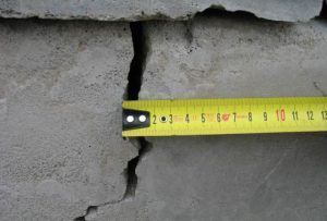
If solid soils are compacted due to the weight of the structure, as a result of which it occurs, this deformation of the foundations is called settlement. As a rule, as a result of settlement, cracks do not appear in the building elements. If the soil settles differently under each of the parts of the building, this can be the reason for the appearance of cracks in individual elements of its structure.
The reason for the uneven settlement of the soil can be:
- the difference in densities and, as a consequence, their unequal compressibility;
- different expansion of its layers as a result of seasonal freezing and thawing;
- unequal formation thickness;
- different loads on the soil from the side of the structure, which leads to different stress states.
There are two reasons why it is necessary to perform the calculation of foundations by deformations. One of them is the structures close to the construction site, which differ significantly in weight.
Scheme of a non-symmetrical pile foundation with the definition of an offset center of gravity.
The second reason for the settlement of foundations can be weak soils. These are bulk soils, loose sands in clay types that are in a fluid state, soils with a high content of organic residues. In such types, deformation of the foundation is possible.
The calculation of the bases consists in checking the fulfillment of the inequality:
S ≤ f, (2)
where S is the calculated absolute value of the settlement;
f is the maximum permissible draft.
Maximum precipitation, at which condition (2) is not met, can be the reason for the formation of an artificial foundation.
The S-value is determined by carrying out compressibility tests in accordance with the established procedure at various points on the construction site. As a result, the maximum Emax and minimum Emin the value of the modulus of compressibility.
The base is considered such that its sediment depends little on the compressibility if Emin = 200 kg / cm², otherwise it is necessary to check the fulfillment of two more conditions:
1.8≤ Emax/ Emin≤ 2.5 (at 200> Emin ≥ 150 kg / cm²);
1,3≤ Emax/ Emin≤ 1.5 (at 150> Emin ≥ 75 kg / cm²);
There are special tables by which the absolute values of the deformation f are determined. Without giving the table, it should be noted that depending on the type of walls and the ratio of the length of the strip foundation to the height of the wall, the maximum draft f varies from 8 to 15 cm.
With respect to Emax/ Emin
For the construction of a house, it is impractical to perform such complex calculations on your own. A mistake made out of inexperience can result in significant material costs.
General Provisions
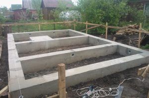
When erecting buildings and structures, a tape support base is often used.The further operation of the structure and its durability depend on the correct calculation of the strength of the strip foundation.
 Strip foundation
Developers of large objects order design documentation for the construction of buildings, houses and structures. When designing, all structures rely on strength to ensure their durable operation. The strength characteristics of the structural elements of the base of the house are especially important.
When an object is small in terms of its volume (a low-rise residential building, summer cottage or other structure), the costs of manufacturing the project are economically unprofitable.
Even with a minimum of construction experience and knowledge, you can calculate the foundation yourself. Today on the Internet there is a lot of information on how to determine the strength of structures and materials for the construction of the base of a house. All methods and calculators of the network for determining the strength properties of the support base of buildings contain general information. However, in each individual case, one cannot do without an independent calculation of the foundation structures.
Determination of resistance to displacement of frozen soil relative to the foundation
1. Resistance
displaced frozen soil relative to the foundation is determined from the table
of the present application depending on the heaving rate ut
and the calculated temperature of the freezing soil Td under the foundation.
2. Speed
heaving of soil Ut, m / day, is determined from the expression
,(1)
wherehfi- deformation of heaving of an unloaded base, determined in
According to ;
td- the duration of the period,
in months, soil freezing under the foundation
,(2)
Here t - the duration of the period with negative air temperatures, in
months, determined in accordance with the chapter of SNiP 2.01.01-82.
d, hNS, df - the same designations as in.
3. Estimated
the temperature of the soil under the foundation is determined by the formula
,(3)
at
,(4)
where Tmin - average temperature
air of the coldest month of the winter period, ° C,
determined in accordance with the chapter of SNiP 2.01.01-82.
table
The values ss
|
Estimated |
Average |
|||||||||||||||||||
|
0,02 |
0,04 |
0,06 |
0,08 |
0,1 |
0,12 |
0,14 |
0,16 |
0,18 |
0,2 |
0,25 |
0,3 |
0,35 |
0,4 |
0,45 |
0,5 |
0,55 |
0,6 |
0,65 |
0,7 |
|
|
-0,6 |
0,5 |
1,1 |
1,6 |
2,2 |
2,7 |
3,3 |
3,8 |
4,4 |
4,9 |
5,5 |
6,8 |
8,2 |
9,6 |
11,0 |
12,3 |
13,7 |
15,1 |
16,4 |
17,8 |
19,2 |
|
-0,8 |
0,6 |
1,2 |
1,8 |
2,4 |
3,0 |
3,6 |
4,2 |
4,8 |
5,4 |
6,0 |
6,6 |
9,1 |
10,6 |
12,1 |
13,6 |
15,2 |
16,7 |
18,2 |
19,7 |
21,2 |
|
-1 |
0,7 |
1,3 |
2,0 |
2,7 |
3,0 |
4,0 |
4,7 |
5,4 |
6,1 |
6,7 |
8,4 |
10,1 |
11,8 |
13,5 |
15,2 |
16,9 |
18,6 |
20,2 |
21,0 |
23,6 |
|
-1,2 |
0,75 |
1,5 |
2,2 |
3,0 |
3,8 |
4,5 |
5,2 |
6,0 |
6,7 |
7,5 |
9,4 |
11,2 |
13,1 |
15,0 |
16,9 |
18,8 |
20,6 |
22,5 |
24,4 |
26,2 |
|
-1,4 |
0,8 |
1,6 |
2,5 |
3,3 |
4,1 |
5,0 |
5,8 |
6,7 |
7,5 |
8,3 |
10,4 |
12,5 |
14,6 |
16,7 |
18,8 |
20,8 |
22,9 |
25,0 |
27,1 |
29,2 |
|
-1,6 |
0,9 |
1,8 |
2,8 |
3,7 |
4,6 |
5,6 |
6,5 |
7,4 |
8,3 |
9,3 |
11,6 |
13,9 |
16,2 |
18,5 |
20,8 |
23,2 |
25,4 |
27,8 |
30,1 |
32,4 |
|
-1,8 |
1,0 |
2,0 |
3,1 |
4,1 |
5,1 |
6,2 |
7,2 |
8,2 |
9,3 |
10,3 |
12,8 |
15,4 |
18,0 |
20,6 |
23,1 |
25,7 |
28,3 |
30,8 |
33,4 |
36,0 |
|
-2 |
1,1 |
2,3 |
3,4 |
4,6 |
5,7 |
6,9 |
8,0 |
9,1 |
10,3 |
11,4 |
14,3 |
17,1 |
20,0 |
22,8 |
25,7 |
28,6 |
31,4 |
34,2 |
37,1 |
40,0 |
|
-2,2 |
1,3 |
2,5 |
3,8 |
5,1 |
6,3 |
7,6 |
8,9 |
10,1 |
11,4 |
12,7 |
15,8 |
19,0 |
22,2 |
25,4 |
28,6 |
31,7 |
34,9 |
38,0 |
41,2 |
44,4 |
|
-2,4 |
1,4 |
2,8 |
4,2 |
5,6 |
7,0 |
8,5 |
9,8 |
11,3 |
12,7 |
14,1 |
17,6 |
21,1 |
24,7 |
28,2 |
31,7 |
35,2 |
38,8 |
42,3 |
45,8 |
49,3 |
|
-2,6 |
1,5 |
3,1 |
4,7 |
6,2 |
7,8 |
9,4 |
10,9 |
12,5 |
14,1 |
15,6 |
19,5 |
23,5 |
27,4 |
31,3 |
35,2 |
39,1 |
43,0 |
47,0 |
50,9 |
54,8 |
|
-2,8 |
1,7 |
3,5 |
5,2 |
6,9 |
8,7 |
10,4 |
12,1 |
13,9 |
15,6 |
17,4 |
21,7 |
26,0 |
30,4 |
34,8 |
39,1 |
43,5 |
47,8 |
52,1 |
56,5 |
60,8 |
|
-3 |
1,9 |
3,8 |
5,8 |
7,7 |
9,6 |
11,6 |
13,5 |
15,4 |
17,4 |
19,3 |
24,1 |
28,9 |
33,8 |
38,6 |
43,4 |
48,3 |
53,1 |
57,9 |
62,8 |
67,6 |
|
-3,2 |
2,1 |
4,2 |
6,4 |
8,6 |
10,7 |
12,9 |
15,0 |
17,2 |
19,3 |
21,5 |
26,8 |
32,2 |
37,6 |
42,9 |
48,3 |
53,7 |
59,0 |
64,4 |
69,8 |
75,1 |
|
-3,4 |
2,4 |
4,7 |
7,2 |
9,5 |
11,9 |
14,3 |
16,7 |
19,1 |
21,5 |
23,8 |
29,8 |
35,8 |
41,7 |
47,7 |
53,6 |
59,6 |
65,6 |
71,5 |
77,5 |
83,4 |
|
-3,6 |
2,6 |
5,3 |
7,9 |
10,6 |
13,2 |
15,9 |
18,5 |
21,2 |
23,8 |
26,5 |
33,1 |
39,7 |
46,3 |
53,0 |
59,6 |
66,2 |
72,8 |
79,4 |
86,1 |
92,7 |
|
-4 |
3,3 |
6,5 |
9,8 |
13,1 |
16,3 |
19,6 |
22,9 |
26,1 |
29,4 |
32,7 |
40,8 |
49,0 |
57,2 |
65,3 |
73,5 |
81,7 |
89,8 |
98,0 |
106,2 |
114,3 |
|
-4,2 |
3,6 |
7,2 |
10,9 |
14,5 |
18, I |
21,8 |
25,4 |
29,0 |
32,7 |
36,3 |
45,4 |
54,4 |
63,5 |
72,6 |
81,6 |
90,7 |
99,8 |
108,8 |
117,9 |
127,0 |
|
-4,4 |
4,0 |
8,1 |
12,1 |
16,6 |
20,1 |
24,2 |
28,2 |
32,2 |
36,3 |
40,3 |
50,4 |
60,4 |
70,5 |
80,6 |
90,7 |
110,8 |
120,9 |
131,0 |
131,0 |
141,0 |
|
-4,6 |
4,5 |
9,0 |
13,4 |
17,9 |
22,4 |
26,9 |
31,3 |
35,8 |
40,3 |
44,8 |
55,9 |
67,1 |
78,3 |
89,5 |
100,7 |
111,9 |
123,1 |
134,3 |
145,5 |
156,7 |
|
-4,8 |
5,0 |
9,9 |
14,9 |
20,0 |
24,9 |
29,8 |
34,8 |
39,8 |
44,7 |
49,7 |
62,1 |
74,6 |
87,0 |
99,4 |
111,9 |
124,3 |
136,7 |
149,1 |
161,6 |
174,0 |
|
-5 |
5,5 |
11,0 |
16,6 |
22,1 |
27,6 |
33,1 |
38,7 |
44,2 |
49,7 |
55,2 |
69,0 |
82,8 |
96,6 |
100,4 |
121,2 |
138,0 |
151,9 |
165,7 |
170,5 |
193,3 |
|
-5,2 |
6,1 |
12,3 |
18,4 |
24,5 |
30,7 |
36,8 |
42,9 |
49,1 |
55,2 |
61,3 |
76,7 |
92,0 |
107,3 |
122,7 |
138,0 |
153,3 |
168,7 |
184,0 |
199,3 |
214,7 |
|
-5,4 |
6,8 |
13,6 |
20,4 |
27,2 |
34,1 |
40,9 |
47,7 |
54,5 |
61,3 |
68,1 |
85,2 |
102,2 |
119,7 |
136,2 |
153,3 |
170,3 |
187,3 |
204,4 |
221,4 |
238,4 |
|
-5,6 |
7,6 |
15,1 |
22,7 |
30,3 |
37,8 |
45,4 |
53,0 |
60,5 |
68,1 |
75,7 |
94,6 |
113,5 |
132,4 |
151,3 |
170,2 |
189,2 |
208,1 |
227,0 |
246,0 |
264,8 |
|
-5,8 |
8,4 |
16,8 |
25,2 |
33,6 |
42,0 |
50,4 |
58,8 |
67,2 |
75,6 |
84,0 |
106,1 |
126,1 |
147,1 |
168,1 |
189,1 |
210,1 |
231,1 |
252,1 |
273,1 |
294,1 |
|
-6 |
9,3 |
18,7 |
28,0 |
37,3 |
46,7 |
56,0 |
65,3 |
74,7 |
84,0 |
93,3 |
116,7 |
140,0 |
163,4 |
186,7 |
210,0 |
233,4 |
256,7 |
280,0 |
303,4 |
326,7 |
Note. For intermediate values Td and Ufmeaning ss adopted by
interpolation.
Calculation of bases
The development should solve the problem of ensuring their stability in any manifestation of unfavorable options for loads and impacts. After all, the loss of stability of the foundations, respectively, will entail deformation, and, possibly, the destruction of all or part of the building.
 Consequences of a foundation shift
The following probable buckling losses are checked:
- shift of the soils of the base together with the foundation;
- flat shear of the structure in contact: the foot of the structure - the surface of the ground;
- displacement of the foundation along any of its axes.
In addition to loads and other forces acting on the structure, the stability of a building depends on the depth, shape, size of the base of the foundation.
Application of the limit state method
The design scheme for determining the loads is quite diverse and specific for each object. At different stages up to 1955, there were different methods for calculating structures: a) permissible stresses; b) breaking loads. From the moment of this date, calculations are carried out according to the method of limit states. Its feature is the presence of a number of coefficients that take into account the ultimate strength of structures. When such structures cease to meet the requirements of operation, their state is called limiting.
The mentioned SP and SNiP establish the following limit states of the bases:
- by bearing capacity;
- by deformations.
 Deformation of the building foundation due to displacement
In terms of bearing capacity, states are included in which the base and structure do not comply with operational standards. This can be their deprivation of a stable position, collapse, all kinds of vibrations, excessive deformations, as an example: subsidence.
The second group unites conditions that complicate the operation of structures or reduce its life. Dangerous displacements can occur here - settlement, roll, deflections, cracks, etc. Calculation based on deformations is always performed.
The grounds are calculated according to the first group in such situations:
- in the presence of horizontal loads - retaining wall, work on deepening the basement (reconstruction), foundations of spacer structures;
- the location of the object near a pit, slope or underground mine;
- the base consists of moist or hard soils;
- the structure is on the list according to the I level of responsibility.
Calculation of loads
The design takes into account all types of loads arising at the stages of construction and operation of buildings and structures. The order of their normative and calculated values is established in SP 20.13330.2011, an updated version of SNiP 2.01.07-85.
Loads are classified according to the duration of exposure, and can be permanent or temporary.
Constant loads include:
- weight of building elements and structures;
- bulk soil weight;
- hydrostatic pressure of groundwater;
- prestressed forces, for example: in reinforced concrete.
 The range of temporary loads is wider. We can say that they include all the others that are not included in the permanent ones.
As a rule, several forces act on a foundation or structure, therefore limit state calculations are performed on the basis of critical load combinations or corresponding forces. Such combinations are designed when analyzing the composition of the simultaneous application of various loads.
The composition of the loads is different:
the main combinations, which include constant, long-term and short-term loads:
Example formula:

special combinations, where, in addition to the main ones, one of the special loads acts:
Example formula:
Characterization of natural bases
Strip foundation diagram.
At the disposal of the builder, nature provides the soil as a natural foundation. The type of foundation is additionally determined by a number of factors: geological structure, depth of groundwater, depth of freezing, etc. The nature of the loads also affects, but for private households it is necessary to focus on a constant load. At the same time, one cannot exclude the possibility that a neighbor will start building a house nearby on driven piles.
The natural foundation is rocky soils (granite, limestone, quartzite, etc.), which are waterproof and reliable for any structures. Similar characteristics are inherent in large-block soils, which were formed from rocks as a result of their destruction. These are crushed stone, gravel, pebbles. They consist of particles larger than 2 mm. Their reliability essentially depends on the presence of groundwater.
Rocks crushed to a size of 0.1-2 mm are called sands. Sands with a particle size of 0.25-2 mm practically do not swell in winter conditions and therefore do not affect the foundation. The reliability of a sand base depends on the thickness of the sand layer and on the impact of groundwater on it.
Strip foundation pouring scheme.
Clay soils contain particles that do not exceed 0.005 mm in size. According to the clay content, they are divided into:
- sandy loam: clay content from 3 to 10%;
- loam: clay content from 10 to 30%;
- loess: is a silty loam.
The most durable base is clay. On this basis, if the clay is dry, massive buildings can be erected.
The bearing capacity of all the listed types of natural substrates is highly dependent on humidity. And wet loess soils are also compacted under the influence of the weight of the structure, sagging heavily.
Some sandy loams, which can turn into quicksands from excess moisture, as well as plant soil, peat, silt and bulk soils, are unsuitable as bases. On such soils, construction is possible after their preliminary compaction.
When you need to do the calculation of the bases for the bearing capacity
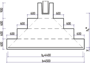 Drawing of the calculation of the foundation for the bearing capacity
- If an existing or new foundation is exposed to significant horizontal loads, especially from buildings under construction in the vicinity or regular vibrations from highways, industrial enterprises.
- The structure was built on a slope, or the slope formed over time, exposing the outside of the base.
- If the base of the foundation is installed on moisture-saturated soils.
- When the buoyancy force of various origins can act on the base.
- If you need to check the stability of natural and artificial slopes.
If visible deformations of structures have already appeared on the construction site or in the foundation of an existing building, always first pay attention to the condition of the soil under the sole and determine their condition. Therefore, according to the standards, there are several different types of soil deformations at once, which depend on internal and external factors.
Precast concrete foundation
The strip support of the precast concrete building is the factory-made foundation blocks, laid in a row around the entire perimeter of the house and inside the site under the load-bearing walls. In some cases, concrete blocks are placed on reinforced concrete cushions.
 Precast concrete blocks
The pillows are mounted close to each other. Sometimes, in order to save money, pillows are placed at intervals, but not on soft soils. Standard reinforced concrete blocks are capable of withstanding the loads from multi-storey buildings. Therefore, the support of low-rise buildings from one row of blocks in height will be very reliable and durable.
When arranging a basement, garage, the blocks are mounted in several rows, creating the walls of the underground room.
The prefabricated blocks are fastened together with cement mortar with the laying of a reinforcing mesh.

