What measurements are they used for?
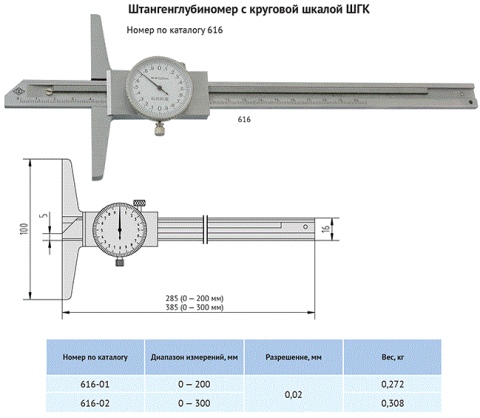
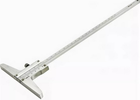
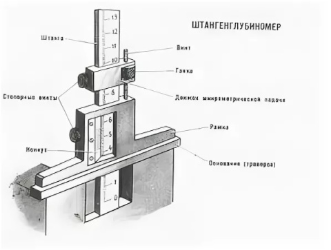
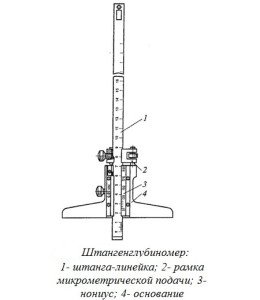
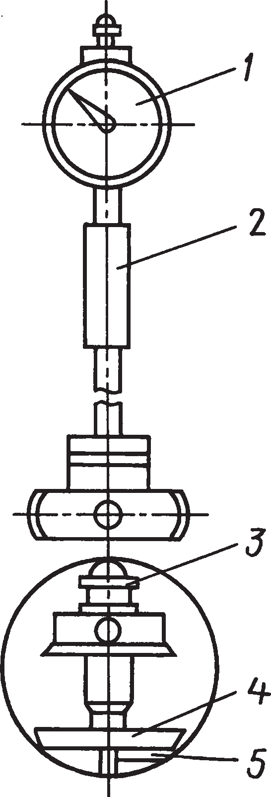
As follows from the above, the purpose of the depth gauge is to measure the depth of the elements of the parts by inserting the end of the rod into the groove or groove. It is necessary that the end of the rod easily enter the area under study and fit snugly against the surface of the part. Therefore, the rods are made of an alloy of increased hardness, and for complex grooves and narrow wells, special inserts are used - measuring needles and hooks - from the same materials.
This tool is used in cases where it is required to obtain the exact size, and the use of a caliper or micrometer is impossible due to the specifics of the shape of the part.
At the same time, it is important to understand how the device works and monitor the effectiveness of its use. There is a simple test of accuracy: take several measurements in a row and compare the results.
If the difference is several times greater than the permissible error limit, then an error was made during the measurements or the device was defective. For calibration, you need to follow the steps described in the verification methodology approved by GOST.
- Prepare the instrument for calibration by washing it to remove dust and debris with detergent.
- Make sure it externally meets the requirements of the standard, the parts and the scale are not damaged.
- Check if the frame moves freely.
- Determine if the metrological characteristics are consistent with the standard. First of all, this concerns the limit, error, measurement range, and the length of the boom overhang. All this is checked with the help of another known working device and a ruler.
Although for mechanical depth gauges according to GOST, an error limit of up to hundredths of a millimeter is declared, if you need guaranteed accuracy, it is recommended to use a depth gauge with a digital type reading device.
How to use?
The measuring principle includes several practical guidelines that should be applied to obtain accurate results. When measuring, fix the frame with a bolt, which is designed so that it does not accidentally move. Do not use tools with damaged rod or vernier (in the case of digital devices, there may be more complex malfunctions) or with a broken zero mark. Take into account the thermal expansion of parts (it is best to take measurements at a temperature close to 20 C).
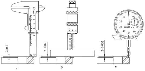
When measuring with a mechanical depth gauge, remember the division value. For most models, it is 0.5 or 1 mm for the main scale and 0.1 or 0.5 mm for the vernier. The general principle is that the number of the division of the vernier, which coincides with the mark of the main scale, must be multiplied by its division price and then added to the whole part of the desired value.
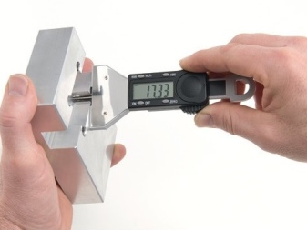
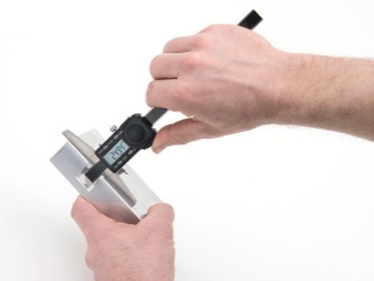
There are several rules for the use and storage of devices to avoid their premature failure:
- the ingress of dust and solid particles between the frame and the rod can cause it to jam, so keep the instrument in the case;
- the service life of mechanical devices is longer than digital ones, and the latter require more careful handling;
- the reading computer and the display must not be subjected to shock and shock;
- for proper operation, power to these components must be supplied from a battery with a normal charge level and / or from a working power supply.
In the next video you will find an overview of the ShGTs-150 depth gauge.
Classification
Height gauges are classified according to various criteria. By design, the following types of device are distinguished:
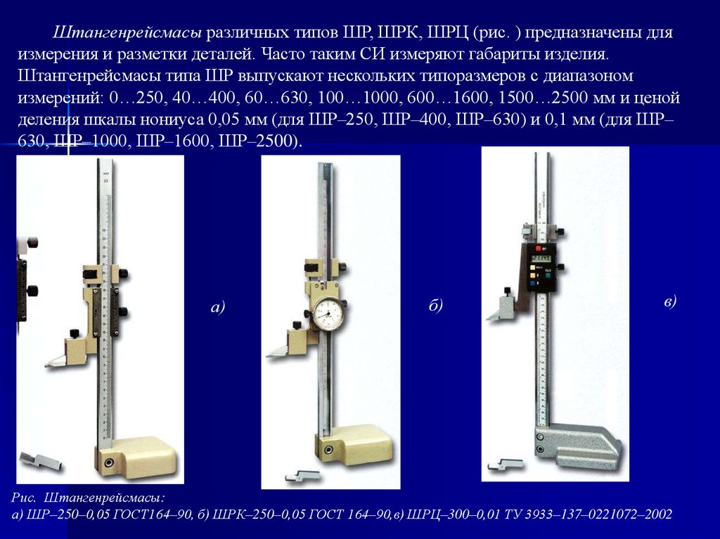
- vernier (SR) - these are those that have already been described above, that is, they resemble a caliper;
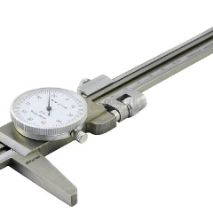
- with a circular scale (ШРК) - devices having a circular reference scale;
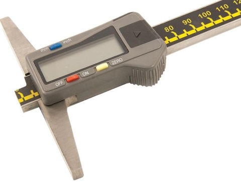
- digital (ШРЦ) - having electronic readout indicators.
In addition, these tools are distinguished depending on the maximum measured length (height) of the parts. This parameter (in millimeters) is included in the model name of the tool.
And there are also models of height gauges with markings ShR-400, ShR-630 and more. The maximum known model is SHR-2500.
All tools are classified according to the accuracy class. It is also included in the model markings. For example, marking ШР 250-0.05 will mean that this model of manual height gauge has a measurement accuracy of 0.05 mm, as indicated by the last figure (0.05). This parameter corresponds to the first class of instrument accuracy according to GOST 164-90. The interval of this class is 0.05-0.09 mm. Starting from 0.1 and higher - the second accuracy class.
For digital devices, there is a separation according to the so-called step of discreteness - from 0.03 to 0.09 mm (for example, ShRTs-600-0.03).
CONTROL AND TEST METHODS
4.1. Verification of the depth gauge - according to GOST 8.163 and MI 965.
4.2. When determining the effect of transport shaking, a shock stand is used that creates a shaking with an acceleration of 30 m / s at a frequency of 80-120 beats per minute. in table. 2. It is allowed to carry out tests of depth gauges by transportation on a truck at a speed of 20-40 km / h for a distance of at least 100 km along a dirt road.
4.3. The impact of climatic factors of the external environment during transportation is determined in climatic chambers in the following modes: at a temperature of minus (50 ± 3) ° С, plus (50 ± 3) ° С and at a relative humidity of (95 ± 3)% at a temperature of (35 ± 5 ) ° C. Exposure in a climatic chamber for each of the three types of tests - 2 hours. After the tests, the error of depth gauges should not exceed the values indicated in table 2.After holding the depth gauge in each mode, it is allowed to keep it under normal conditions for 2 hours.
Specifications
Table 1 - Metrological characteristics
|
Description of characteristics |
Meaning |
|||||
|
SHG- 160 |
SHG- 200 |
SHG- 250 |
SHG- 300 |
SHG- 400 |
SHG- 630 |
|
|
Measurement range, mm |
from 0 to 160 |
from 0 to 200 |
from 0 to 250 |
from 0 to 300 |
from 0 to 400 |
from 0 to 630 |
|
Reading value according to vernier, mm |
0,05 |
|
Description of characteristics |
Meaning |
|
|
SHG-SHG-SHG-TTTG-TTTG- 160 200 250 300 400 |
SHG- 630 |
|
|
Length of the measuring surface of the frame, mm, not less |
120 |
175 |
|
Deviation from flatness of the measuring surface of the frame, mm |
0,006 |
|
|
Deviation from flatness of the stays measuring surface, mm |
0,004 |
|
|
Roughness parameter of the measuring surface of the frame, mm |
Ra |
|
|
Roughness parameter of the measuring surface of the rod, mm |
Ra |
|
|
Distance from the upper edge of the vernier edge to the scale surface of the depth gauge rod, mm, not more |
0,25 |
|
|
Angle of the vernier scale plane relative to the rod scale plane, °, not more |
30 |
|
|
Line width of the bar and vernier scales, mm |
from 0.08 to 0.20 |
|
|
The difference in the width of the lines within one scale and the lines of the scales of the rod and vernier of the same depth gauge, no more, mm |
0,03 |
Table 2 - Limits of permissible absolute error of depth gauges
|
Description of characteristics |
Scale value |
|
|
0 to 400 mm incl. |
St. 400 to 630 mm |
|
|
Limits of permissible absolute error of depth gauges at ambient temperatures from plus 10 ° C to plus 30 ° C and relative humidity up to 80% at a temperature of plus 25 ° C, mm |
±0,05 |
±0,10 |
Note - the error is given with both tightened and loose clamping of the frame. Table 3 - Main technical characteristics_
|
Modification |
Overall dimensions (length x width x height), mm, no more |
Weight, kg, no more |
|
SHG-160 |
250x120x11.4 |
0,30 |
|
SHG-200 |
290x120x11.4 |
0,31 |
|
SHG-250 |
340x120x11.4 |
0,33 |
|
SHG-300 |
390x120x11.4 |
0,36 |
|
SHG-400 |
490x120x11.4 |
0,39 |
|
SHG-630 |
720x175x11.4 |
0,48 |
Specifications
Table 1. Basic metrological and technical characteristics of depth gauges with a rod in standard version_
|
Measurement range, mm |
Reading value according to vernier, mm |
Step of discreteness of digital reading device, mm |
Length of the measuring surface of the frame, mm, not less |
|
from 0 to 150 |
0,02; 0,05; 0,10 |
0,01 |
102; 120; 175 |
|
from 0 to 160 |
0,02; 0,05; 0,10 |
0,01 |
102; 120; 175 |
|
from 0 to 200 |
0,02; 0,05; 0,10 |
0,01 |
102; 120; 175 |
|
from 0 to 250 |
0,02; 0,05; 0,10 |
0,01 |
102; 120; 175 |
|
from 0 to 300 |
0,02; 0,05; 0,10 |
0,01 |
102; 120; 175 |
|
from 0 to 400 |
0,05; 0,10 |
0,01 |
102; 120; 175 |
|
from 0 to 500 |
0,05; 0,10 |
0,01 |
102; 120; 175 |
|
from 0 to 600 |
0,05; 0,10 |
0,01 |
102; 120; 175 |
|
from 0 to 630 |
0,05; 0,10 |
0,01 |
102; 120; 175 |
|
from 0 to 1000 |
0,05; 0,10 |
0,01 |
102; 120; 175 |
Table 2. Main metrological and technical characteristics
depth gauges with L-shaped bar
|
Measurement range, mm |
Reading value according to vernier, mm |
Step of discreteness of digital reading device, mm |
Length of the measuring surface of the frame, mm, not less |
|
from 0 to 150 |
0,02; 0,05; 0,1 |
0,01 |
102; 120; 175 |
|
from 0 to 160 |
0,02; 0,05; 0,1 |
0,01 |
102; 120; 175 |
|
from 0 to 200 |
0,02; 0,05; 0,1 |
0,01 |
102; 120; 175 |
|
from 0 to 250 |
0,02; 0,05; 0,1 |
0,01 |
102; 120; 175 |
|
from 0 to 300 |
0,02; 0,05; 0,1 |
0,01 |
102; 120; 175 |
Table 3. Limits of permissible absolute error of depth gauges at ambient temperature (20 ± 5) ° С_
|
Measured depth, mm |
Limits of permissible absolute error of depth gauges, mm |
|||
|
with vernier reading value, mm |
with discreteness step of digital reading device, mm |
|||
|
0,02 |
0,05 |
0,10 |
0,01 |
|
|
from 0 to 100 incl. |
± 0,02 |
± 0,05 |
± 0,05 |
± 0,03 |
|
St. 100 to 200 incl. |
± 0,03 |
± 0,05 |
± 0,05 |
± 0,03 |
|
St. 200 to 300 incl. |
± 0,04 |
± 0,05 |
± 0,05 |
± 0,04 |
|
St. 300 to 400 incl. |
— |
± 0,05 |
± 0,10 |
± 0,04 |
|
St. 400 to 600 incl. |
— |
± 0,10 |
± 0,10 |
± 0,05 |
|
St. 600 to 800 incl. |
— |
± 0,10 |
± 0,15 |
± 0,07 |
|
St. 800 to 1000 |
— |
± 0,15 |
± 0,15 |
± 0,07 |
The deviation from the flatness of the measuring surface of the rod is not more than 0.004 mm. The deviation from the flatness of the measuring surface of the frame is not more than 0.006 mm. Operating temperature range from 15 to 25 ° С.
Relative air humidity no more than 80% at a temperature of 25 ° C.
Heck. 4
Heck. 4
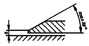
2.9.2. Distance a from the upper edge of the vernier edge to the surface of the bar scale should not exceed 0.25 mm for vernier depth gauges with a vernier reading value of 0.05 mm and 0.30 mm for depth gauges with a reading value of 0.1 mm.
2.9.3. The dimensions of the bars of the barbell and vernier scales must correspond to the following: the width of the bars is 0.08-0.20 mm; the difference in the width of the bars within one scale and the bars of the scales of the barbell and the vernier of one vernier depth gauge should not be more than 0.03 mm when counted according to the vernier 0, 05 mm; 0.05 mm when reading vernier 0.1 mm.
2.10. Requirements for the dial scale of the reading device (type ShGK)
2.10.1. The scale division must be at least 1 mm.
2.10.2. The scale line width is 0.15-0.25 mm. The difference in the width of the corresponding lines within one scale should be no more than 0.05 mm.
2.10.3. The width of the arrow above the scale marks should be 0.15-0.20 mm. The end of the arrow should overlap short strokes by no more than 0.8 of their length. The distance between the end of the hand and the dial must not exceed 0.7 mm.
2.10.4. The reading device should provide the ability to align the arrow with the zero mark on the dial.
2.11. Requirements for ShGTs type depth gauges
2.11.1. The figures must be at least 4 mm high.
2.11.2. Depth gauges of the SHGTs type may additionally be equipped with an interface for outputting the measurement result to an external device.
2.12. The hardness of the hardened measuring surfaces of the depth gauge should be: from tool and structural steel - not less than 59 HRC; from high-alloy steel - not less than 51.5 HRC.
2.13. The roughness parameter of the measuring surfaces according to GOST 2789: frames - 0.08 microns; rods - 0.16 microns.
2.14. The outer surfaces (with the exception of the measuring surfaces of the frame and the rod) of depth gauges made of tool or structural steel must be chrome-plated.
2.15. The bar and vernier scales of stainless steel depth gauges should have a matte finish.
2.16. The depth gauge must be demagnetized.
2.17. Mean time between failures of a depth gauge - 30,000 conditional measurements. Under a conditional measurement, we mean the movement of the frame along the rod until the measuring surfaces contact the object of measurement. In this case, the movement of the frame should be at least 1/3 of the upper measurement limit of the depth gauge.
2.18. The established failure-free operating time of the ShG and ShGK type depth gauges is at least 6000 conventional measurements; the ShGTs type depth gauge - at least 9000 conventional measurements. 2.2 and / or 2.6.
2.19. The total average service life of the depth gauge is at least 5 years.
2.20.The established full service life of the ShG-type depth gauge is at least 1.5 years; type ShGK - at least 2.0 years; type SHGTs - at least 2.5 years. The criterion of the limiting state is the wear of the elements of depth gauges, leading to non-compliance with the requirements of paragraphs. 2.2 and (or) 2.6 and characterized by the impossibility or inappropriateness of the restoration of worn surfaces.
2.21. The average recovery time of a vernier depth gauge with a vernier is no more than 2 hours, with a dial and a digital reading device - no more than 4 hours.
2.22. The average shelf life should be at least 4 years, subject to re-preservation after 2 years.
2.23. A passport according to GOST 2.601 must be attached to each depth gauge.
2.24. Marking
2.24.1. Each depth gauge must bear the following: trademark of the manufacturer; serial number according to the manufacturer's numbering system; conventional designation of the year of manufacture; value of reading according to vernier or scale division price.
2.24.2. The marking on the case is in accordance with GOST 13762. The name or symbol of the depth gauge is applied only on the hard case.
2.25. Package
2.25.1. Methods and means for degreasing and preserving the depth gauge - in accordance with GOST 9.014.
2.25.2. A depth gauge should be packed in a case made of material in accordance with GOST 13762. For a vernier depth gauge with an upper measurement limit of up to 400 mm, soft packing is allowed.
TECHNICAL REQUIREMENTS
2.1. Depth gauges should be manufactured in accordance with the requirements of this standard according to working drawings approved in the prescribed manner.
2.2. The maximum permissible error of the depth gauge both with loose and tightened clamping of the frame at an ambient temperature of (20 ± 10) ° С, relative humidity of no more than 80% at a temperature of 25 ° С should correspond to that indicated in table. 2.
table 2
mm
|
Depth gauge permissible error limit (±) |
|||||
|
Scale sections |
with vernier counting value |
with the division value of the dial of the reading device |
with a discreteness step of a digital reading device |
||
|
0,05 |
0,1 |
0,02 |
0,05 |
0,01 |
|
|
Up to 100 |
0,03 |
0,03 |
|||
|
» 200 |
0,05 |
0,05 |
0,05 |
||
|
200 » 300 |
|||||
|
300 » 400 |
0,04 |
0,04 |
|||
|
400 » 600 |
0,10 |
0,10 |
|||
|
600 » 800 |
— |
— |
— |
||
|
800 » 1000 |
0,15 |
0,15 |
Note. The error of the depth gauge should not exceed the values indicated in table. 2, when checking them against plane-parallel gauge blocks made of steel.
2.3. The flatness tolerance of the measuring surface of the depth gauge rod is 0.004 mm.
2.4. The flatness disc of the measuring surface of the frame of depth gauges of the ShG and ShGK types is 0.006 mm, of the ShGTs type - 0.005 mm. Blocks are allowed along the edges of the measuring surfaces in a zone no more than 0.2 mm wide.
2.5. The backlash of the micrometric pair of the micrometric frame feed should not exceed 1/3 of a turn.
2.6. The frame should not move along the rod under its own weight when the rod is in a vertical position. The depth gauge must have a device for clamping the frame, which ensures its locking in any position within the measuring range.
2.7. The measuring surface of the rod must be made of carbide. (Carbide according to GOST 3882). At the request of the consumer, the measuring surface of the rod may not be equipped with hard alloy. The rod of the depth gauge must have a hardness of at least 30 HRC.
2.8. At the request of the consumer, the depth gauge must measure the dimensions of grooves, grooves and the depth of holes with a diameter of at least 2 mm.
2.9. Requirements for the bar and vernier scales (type SHG)
2.9.1. The location of the plane of the vernier scale relative to the plane of the bar scale is indicated in fig. 4.
Description
Height gauges are manufactured in the following types:
SHR - with counting according to vernier;
ShRK - with a reading device with a circular scale;
ShRTs - with an electronic digital reading device.
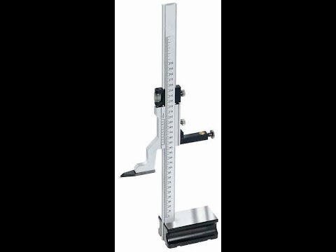
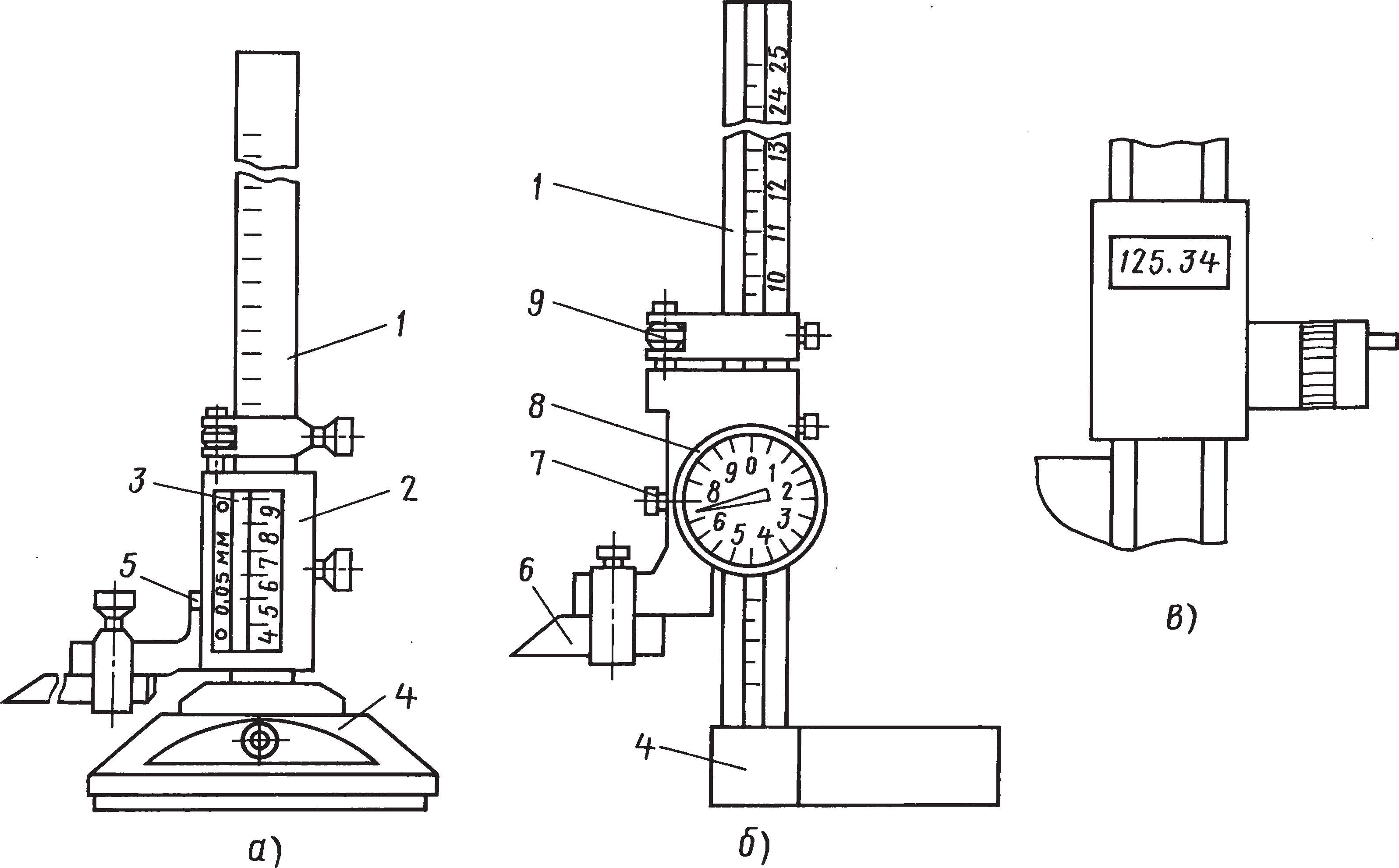
The principle of operation of height gauges such as ShR is mechanical. The dimensions are counted by the method of direct assessment of the coincidence of the scale divisions on the bar with the vernier divisions located on the frame of the height gauge.Height gages of the ShR type consist of a base, a rod with a millimeter scale fixed to the base, a frame with a vernier moving along the rod, a micrometric feed device, and a measuring leg.
The principle of operation of height gauges of the ShRK type is mechanical. The dimensions are counted by the method of direct assessment by millimeter divisions of the bar scale and by divisions of the circular scale built into the frame. The dial rotates by means of a movable bezel and is locked with a set screw. ShRK-type height gauges consist of a base, a bar fixed to the base, on which a millimeter scale is applied, a frame with a circular scale moving along the bar, a micrometer feed device, and a measuring leg.
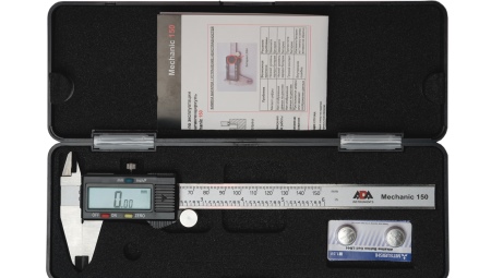
The principle of operation of height gauges of the SHRTs type is mechanical with the output of readings on a liquid crystal (LCD) screen of an electronic digital reading device. The dimensions are counted directly by reading the indications on the LCD screen of an electronic digital reading device located on the frame of the height gauge. ShRTs type gages consist of a base, a rod fixed to the base, a micrometric feed device, a measuring foot, a frame with a digital reading device, on the front panel of which buttons are installed, with the help of which a number of special functions are carried out (for example, turning on / off the digital reading device ( ON / OFF), selection of units of measurement in inches or millimeters (mm / inch), zeroing the measurement result (0), selection of absolute or relative measurements (ABS), etc.).
All moving elements of the height gauge are equipped with locking screws.
Sealing of the body of height gauges against unauthorized access is not provided.
(s) - The trademark "AO KZ" Krasny Instrumentalschik "is applied to the passport of height gauges by typographic method, on a bar or dial (for height gauges ShRK) and on the cover of the case with paint or by laser marking.
What it is?
First of all, it is worth giving general information about this locksmith tool.
- It also has another name - height-gauge.
- It looks like a vernier caliper, but is installed to determine dimensions on a horizontal plane in a vertical position.
- The principle of operation of the caliper is no different from the principle of operation of the caliper.
- Its purpose is to measure the height of parts, the depth of the holes and the relative position of the surfaces of various body parts. In addition, it is used for marking operations.
- Since the instrument is, in fact, a measuring device, it has a certain method of verification and measurement.
- Regulates the technical conditions of this instrument GOST 164-90, which is its main standard.
TESTING TOOLS
2.1. The list of verification tools is shown in table. 2.
table 2
|
Recommendation item number |
Name of an exemplary measuring instrument or verification aid; number of the document regulating the technical requirements for the product; category according to the state verification scheme and (or) metrological and basic technical requirements |
|
Fluxgate pole detector FP-1 |
|
|
Probe according to TU 2.034.225, thickness, mm, 0.25; 0.30 |
|
|
Instrument microscope according to GOST 8074 |
|
|
Surface roughness samples according to GOST 9378 with parameters R = 0.08 μm and R = 0.16 μm; magnifier LP-1-4x according to GOST 25706 or model 295 profiler according to TU2.034.4; |
|
|
Linear rulers, type LT or LD, accuracy class 1 in accordance with GOST 8026; plane-parallel gauge blocks of accuracy class 2 in accordance with GOST 9038; flat glass plate of accuracy class 2 according to TU 3.3.2123 |
|
|
Checking plate of accuracy class 1 or 2 in accordance with GOST 10905 plane-parallel gauge blocks of the 3rd accuracy class in accordance with GOST 9038; or exemplary 4th category according to MI 1604 flat glass plate of accuracy class 2 according to TU 3.3.2123 |
|
|
Mechanical stopwatch with a scale division of 0.1 s, accuracy class 1 in accordance with GOST 5072 |
Notes (edit): 1. It is allowed to use funds not listed in table., but meeting the accuracy requirements of this recommendation.
Description
Height gauges consist of a base with a vertical guide (rod) fixed on it, along which a frame with a reading device moves. The frame with the reading device is equipped with a measuring (or marking) foot and freely moves along the rod.
Height gauges are manufactured in the following versions:
SHR - with counting according to vernier;
ShRK - with a reading device with a circular scale;
ShRTs - with an electronic digital reading device.
The principle of operation of height gauges is mechanical.
The measurement of the dimensions of the ShR height-gage is made by the method of direct assessment of the coincidence of the scale divisions on the bar with the vernier divisions located on the frame of the height-gage.
The dimensions of the ShRTs height gauge are counted directly by reading the readings on the liquid crystal screen of a digital reading device located on the frame of the height gauge. Next to the liquid crystal display there are buttons for turning on / off the electronic digital reading device (OFF / ON), setting zero (ZERO), selecting the mode of units of measurement mm / inch (mm / inch), etc. ...
The dimensions of the ShRK height gauge are counted according to the bar scale and the circular scale of the reading device.
Height gauges have a device for clamping the frame, which ensures its locking in any position within the measurement range. Frame design and leg attachment are subject to change without affecting performance.
Height gages of ShR version with vernier counting 0.05 and 0.1 mm and measuring range from 0 to 250 mm, from 40 to 400 mm, from 60 to 630 mm, from 100 to 1000 mm, from 600 to 1600 mm, from 1500 to 2500 mm are manufactured in accordance with GOST 164-90. The rest of the height gauges are manufactured according to the technical specifications TU 3933-015-74229882-2013.
The appearance of the ShR, ShRTs, ShRK height gauges is shown in Figures 1, 2, 3.
a) height gage with a marking foot b) height gage with a measuring foot
Figure 1 - General view of the ShR height gauge


