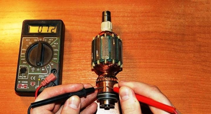
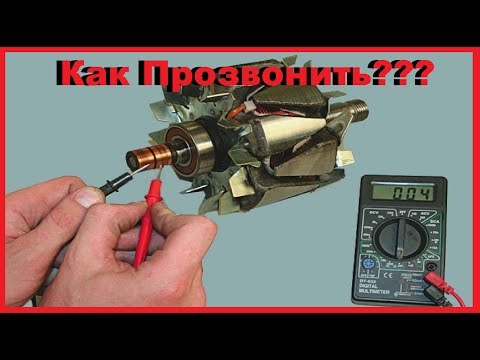
How to check with a multimeter
-
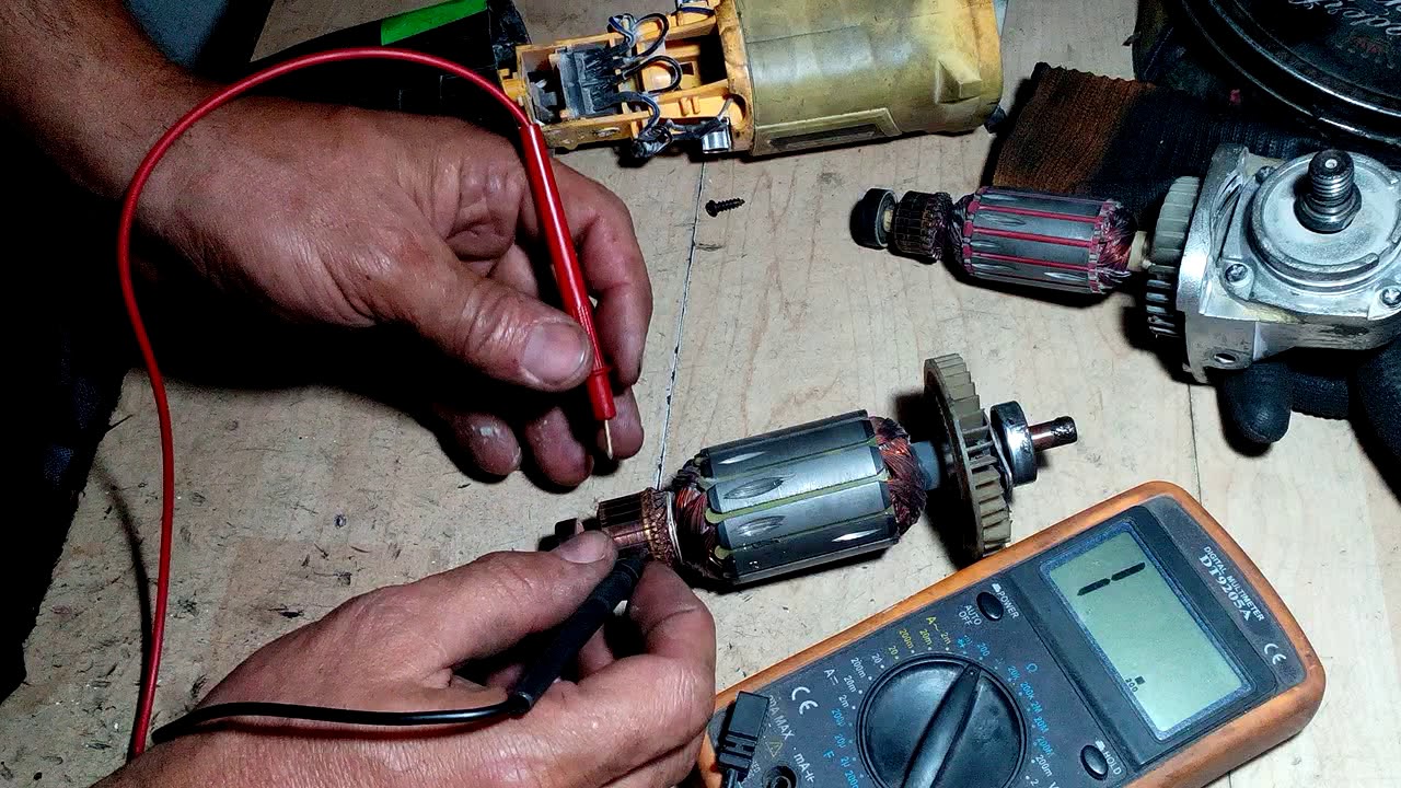
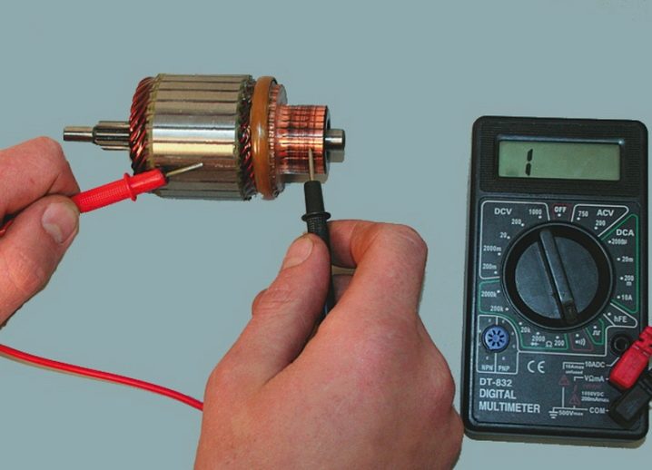
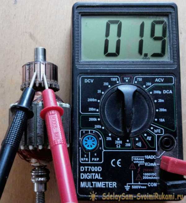
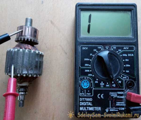
Put a resistance of 200 ohms. Connect the test leads of the instrument to two adjacent lamellas. If the resistance is the same between all adjacent plates, then the winding is in good order. If the resistance is less than 1 ohm and very close to zero, there is a short circuit between the turns. If the resistance is two or more times higher than average, then there is a break in the winding turns. Sometimes, when there is a break, the resistance is so great that the device goes off scale. On an analog multimeter, the arrow will go all the way to the right. And on digital it will not show anything.
- The determination of the breakdown to ground is done in the absence of a winding break. Set the maximum resistance on the scale of the device. Depending on the tester, it can be from 2 MΩ to 200 MΩ. Connect one probe to the shaft, and the other to each plate in turn. In the absence of faults, the resistance should be zero. Do the same with the rotor. Connect one probe to the iron body of the rotor, and move the other along the lamellas.
Video: how the check goes
If you don't have a tester, use a 12 volt light bulb up to 40 watts.
How to check the grinder rotor with a light bulb
- Take two wires and connect them to the lamp.
- Make a break on the negative wire.
- Apply voltage to the wires. Attach the ends of the gap to the collector plates and twist it. If the light is on without changing the brightness, then there is no short circuit.
- Conduct a short to iron test. Connect one wire to the lamellas and the other to the rotor iron. Then with the shaft. If the light is on, then there is a breakdown to ground. The winding closes to the rotor housing or shaft.
This procedure is similar to diagnostics with a multimeter.
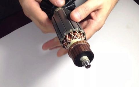
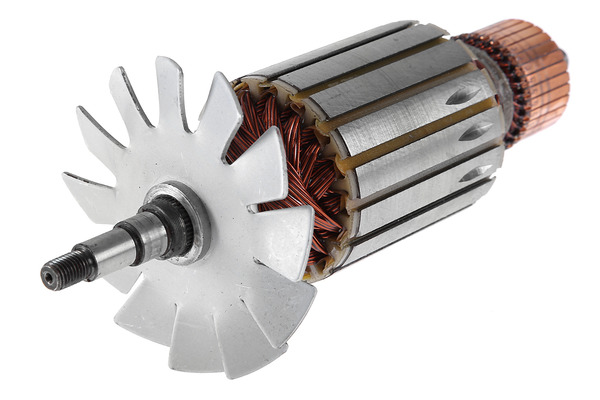
How to repair an anchor at home
Due to the anchor, a third of the breakdowns of the screwdriver occurs. With daily intensive operation, malfunctions can occur already in the first six months, for example, if the brushes are not replaced on time. With sparing use, the screwdriver will last a year or more.
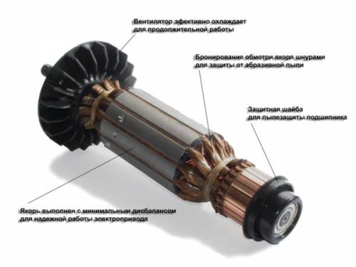
The anchor can be salvaged if the balance is not disturbed. If during the operation of the device an intermittent hum is heard and there is a strong vibration, then this is a violation of balance. This anchor must be replaced. And you can repair the winding and the collector. Small short circuits are eliminated. If a significant part of the winding is damaged, it can be rewound. Grind worn out and heavily damaged lamellas, build up or solder. In addition, you should not undertake an anchor repair if you are unsure of your capabilities. Better to replace it or take it to the workshop.
Collector bore
Over time, the brush develops on the collector. To get rid of it, you must:
-
Grind the manifold using longitudinal cutters, that is, through cutters.
-
We also need a reverse taper for centering on the bearing. Make a hole in it up to 8 mm.
- Since copper is stringy, adjust the machine at 600 to 1500 rpm.
- Primary feed in half division. When the cutter slightly touches the workpiece, make a longitudinal groove of the entire manifold. According to the resulting shiny pattern, you will see the condition of the lamellas, all the irregularities of the surfaces.
- If the manifold is flat, the bore will be uniform.
- If there are pits, continue grooving until the surface is leveled.
- For the last pass, you need to feed the cutter one fourth of the division.
- For polishing, take a thousand-grit sandpaper and turn on the machine so that the armature rotates in the direction that it rotates during operation.
Do not forget to clean the rotor from swarf to avoid short circuiting.
Related Videos
How to rewind an anchor
Before disassembling the armature, write down or sketch the direction of the winding. It can be left or right. To determine it correctly, look at the end of the armature from the collector side.Put on gloves, use sharp cutters or a metal hacksaw. Remove the winding ends. The manifold needs to be cleaned, but it is not necessary to remove it. Carefully, without damaging the slot insulators, knock out the rods of the remaining parts of the winding using a hammer and a metal chisel.
Video: Remove the winding
Using a file, without damaging the insulator film, remove the impregnation residues. Count the conductors in the slot. Calculate the number of turns in the section and measure the wire diameter. Draw a diagram. Cut insulation sleeves from cardboard and insert them into the grooves.
Video: Winding Left and Right
After winding, weld the leads of the sections with the collector cockerels. Now check the winding with a tester and short circuit indicator. Proceed with impregnation.


Impregnation instructions (including speed controller)
- After making sure that there are no problems, send the anchor to the electric oven to warm up for better epoxy flow.
-
After warming up, place the anchor on the table at an angle for better flow through the wires. Place a drop of resin on the forehead and slowly twist the anchor. Drip until glue appears on the opposite frontal area.
- Position the anchor horizontally and drip onto both foreheads. Twist the anchor until it loses fluidity.
-
Leave in an upright position until complete polymerization.
At the end of the process, lightly grind the manifold. Balance the anchor with dynamic balancing and grinder. Now grind finally on the bearing. It is necessary to clean the grooves between the lamellas and polish the collector. Make a final check for open and short circuits.
The peculiarity of the winding for grinders with a variable speed is that the rotor is wound with a power reserve. The current density affects the speed. The wire cross-section is overestimated, and the number of turns is underestimated.
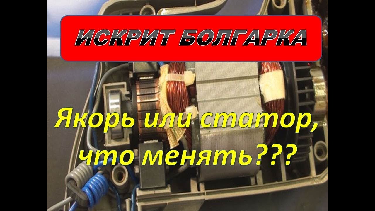
How to check the stator winding of the angle grinder at home in different ways
There are a large number of different electrical devices with which you can diagnose the stator. However, at home, a limited number of technical means are used. Some are presented in the following videos.
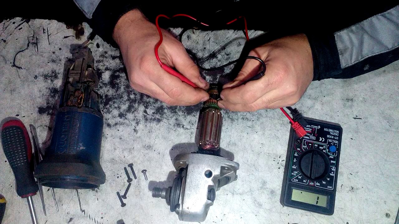
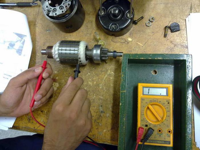
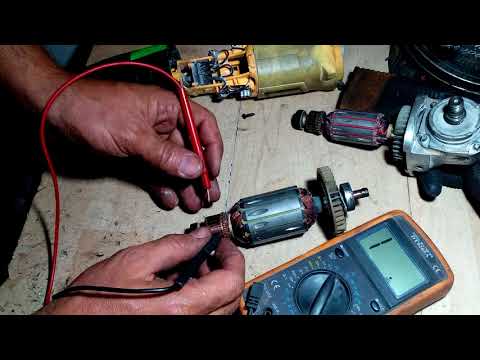
Checking the armature / rotor and stator with a multimeter / tester
In the following video, a multimeter device, or, as more commonly called a tester, is used as a tool for diagnosing the rotor and stator of an electric drive. It is used to measure various electrical parameters: resistance, current, voltage. To determine faults in the form of wire breakage, breakdown of the winding to the case, the "ohmmeter" mode is used, that is, a certain resistance value is set, which is comparable to that available in the tested circuit. In this case, with a limit of 200 ohms.
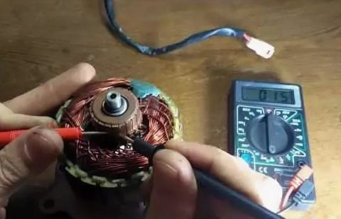
Breakdown of the stator to the housing is determined by applying indicator probes to its housing and one of the ends of the winding. The presence of any resistance value on the indicator indicates the presence of a defect in the form of a breakdown of the winding onto the case. When diagnosing a winding break, the indicator of the device will not show anything when the probes are combined with the winding leads.
More complex manipulations should be carried out when checking the rotor windings of the electric drive. A winding break can be in any connection with a separate collector lamella. Therefore, it is necessary to check the resistance between all lamellas of the collector, applying indicator probes to them one by one. In the absence of an open circuit, the resistance will have the same small value in all cases. Any deviation indicates the presence of a cliff. The breakdown of the winding on the case is checked with probes when they come into contact with the collector and "iron" from a set of sheets of electrical steel. The indicator scale should not react to this action.
However, it is impossible to determine the turn-to-turn circuit with a multimeter. Here, a device called the indicator of short-circuited loops (IKZ) is used.More details about it in the information below.
On turn-to-turn circuit, indicator
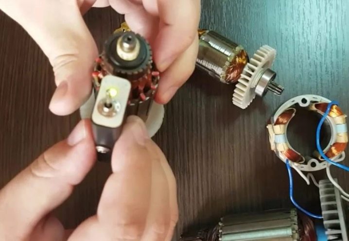
The principle of operation of the device for determining the turn-to-turn closure is shown in the following video. The device in the tested winding induces a magnetic field. In the presence of short-circuited turns in the winding, the short-circuit current causes increased resistance to the electromagnetic field generated by the device. By adjusting the IKZ, a setting is performed, upon reaching which a light signal is triggered (the indicator lamp changes color from green to red) or a sound is heard. In addition to the main application, the author shows a way to determine the places of connection of the winding wires to the collector lamellas, in the absence of visually visible contacts.
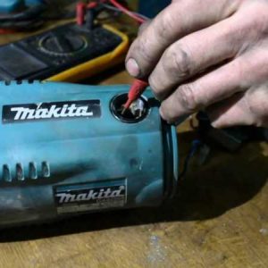
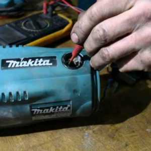
Makita, without instruments
In one of the Makita models in the next video, smoke went off during operation, which is a sure sign of a burnt out rotor or stator. To determine the reasons, the author performed a complete disassembly of the grinder, which makes it possible to perform a good external examination of the grinder units suspected of malfunctioning. If there were no signs of smoke consequences on the rotor, then on the stator several places of burnt electrical insulating varnish were clearly visible.
Important: after a visual inspection, it is necessary to check again with the help of instruments that unit on which no external flaws were found. So, for example, in this case, a multimeter found breaks in the winding on the rotor. By the way, an external examination turned out to be enough on the stator, since the multimeter could not determine the defect in the form of an interturn circuit
By the way, an external examination turned out to be enough on the stator, since the multimeter could not determine a defect in the form of an interturn short circuit.


Multimeter - automatic: quickly and efficiently performs measurements
The multimeter, which is presented in the next video, is convenient to use and allows you to take readings without unnecessary fuss, when the measured values "jump" at a device that does not have such an option. A method for determining the measurement error associated with the resistance of the indicator probes is shown. The approximate value of the winding resistance is given, where there are no faults.
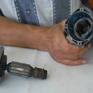
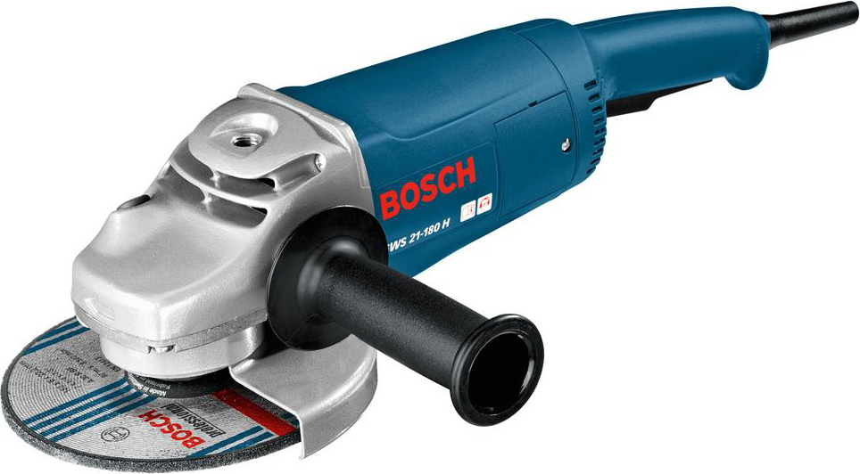
Dismantling the Bosch grinder with your own hands
For the owner of a power tool, knowledge of its device and the ability to disassemble is a must.
Knowing the procedure for disassembling the grinder allows you to independently perform such work as changing lubricants, changing bearings and carbon brushes.
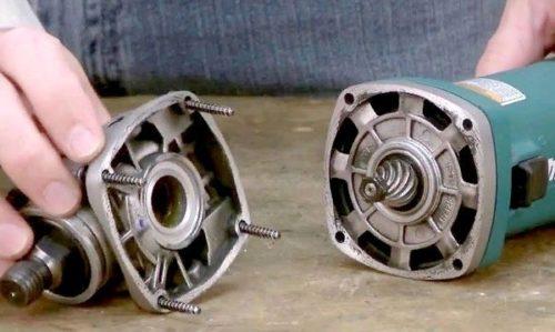
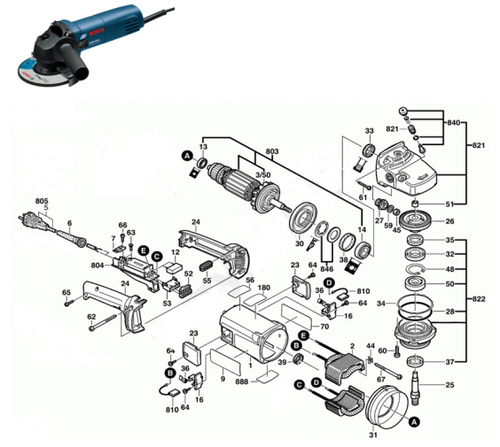
To disconnect the gearbox housing poz.821 from the stator housing poz.888, it is necessary to disassemble (remove) the housing of the grinder handle poz.24.
This operation must be performed in order to get the carbon brushes pos. 810 holding the rotor collector.
At the second stage, unscrew the 4 (four) screws, pos. 61, securing the gearbox and stator housings.
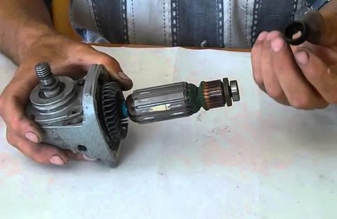
Having pulled out the rotor together with the gearbox, proceed to dismantle the gearbox.
Repair of the Bosch grinder begins with the disassembly of the gearbox pos. 821. Disassembly of the gearbox begins with unscrewing 4 (four) screws, pos. 60. As a rule, the screws are screwed into the sealant at the factory. You will have to make some effort.
Let's note right away! Low-power Bosch grinders use spur gears in the gearbox. For grinders with a power of over 1000 W, helical gears are used in gearboxes.
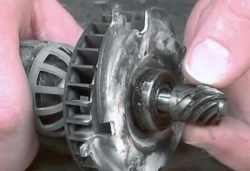
How to remove the driven gear
After removing the gear cover, you can get the helical gear assembly, pos. 26.
To remove the gear, you need to use a press or a puller. But using a puller is difficult, since it requires the use of special thin jaws.
Before removing the helical gear, check the backlash of the gear connection, the integrity of the teeth, the contact patch.
On the shaft of the spindle, pos. 26, a bearing, pos. 50, is pressed. If the bearing has a large play, makes noises when rotating, the lubricant has dried out, it is preferable to replace it.
To remove the bearing, it is necessary to remove the gear, circlip and dismantle the bearing. If, when removing the rotor shaft assembly, the bearing remains in the gear housing, the bearing is removed using a hammer and a soft tip.
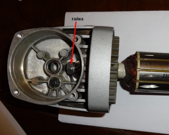
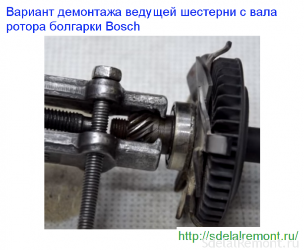
How to remove the drive gear of a Bosch grinder
The drive gear, pos. 27, is removed from the rotor shaft in the following sequence:
- clamp the rotor by hand and, using an open-end wrench, unscrew the nut pos. 45 counterclockwise .;
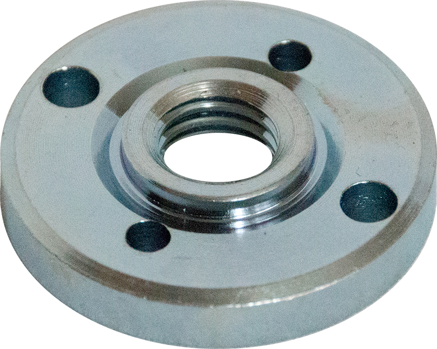
- remove the washer pos. 59 .;
- pull out the leading helical gear pos. 27.
Visually check the integrity of the gear teeth, contact patch.
If the gears are badly worn (licked), there are chipped teeth, then they must be replaced. Moreover, the replacement of gears is always done in pairs.

In low-power Bosch grinders, a needle bearing is used as a support bearing in the gearbox.
Do-it-yourself bosch grinder repair follow the instructions strictly provided. If you need to remove the needle bearing from the housing, you can't do without some quick wits. Its dismantling is performed only upon destruction.
To get a destroyed bearing race, you can use a proven method.
A tap is selected with a diameter slightly larger than the inner diameter of the destroyed needle bearing holder
The tap is fixed in the chuck of the screwdriver and screwed carefully at low speeds into the holder. When the tap reaches the bottom of the gear case, it will begin to lift the clip. In addition to the needle bearing of the spindle shaft, Bosch grinders use two more bearings mounted on the rotor shaft
In addition to the needle bearing of the spindle shaft, Bosch grinders use two more bearings mounted on the rotor shaft.
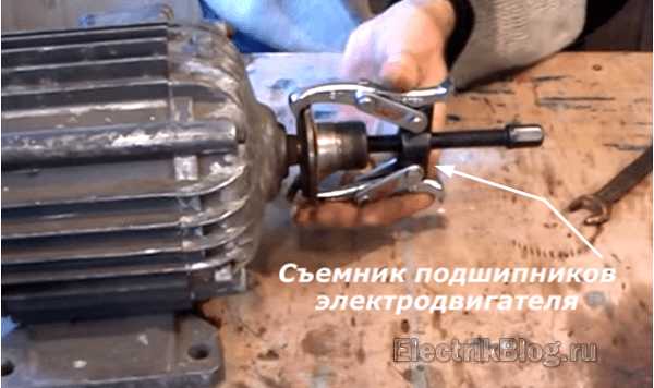
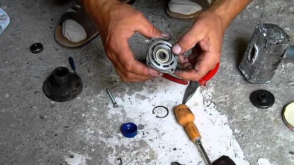
How to remove bearings from a Bosch grinder rotor
It is recommended to use pullers to dismantle the bearings from the rotor pos. 803 of the Bosch grinder.
The bearing pos. 15 near the collector can be easily removed, but to remove the bearing pos. 14 from the impeller side it is complicated by the fact that a number of preparatory operations must be performed.
Bearing pos. 15 is closed with a soft rubber seat. A similar rubber protection pos. 33 also covers the bearing pos. 14.
To dismantle the bearing, pos. 14, unscrew the nut, pos. 45, remove the spur gear, pos. 17, and the plastic protection, pos. 33. Using a puller, you can easily dismantle the bearing from the rotor shaft.
And if there is no puller? A vice, two metal strips and a hammer with a soft metal guide will come to the rescue.
Dismantling the Bosch grinder
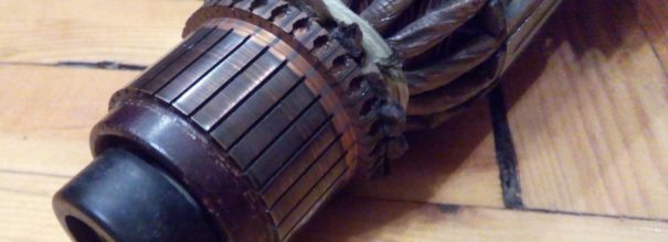
Work with an ohmmeter
Sincere could occur due to the loss of electrical contact in one of the lamellas. To measure resistance, it is recommended to install the probes on the side of the current collectors. Rotating the motor shaft, watch the dial readings. There should be zero values on the screen. If numbers slip even in a few ohms, then this speaks of soot. When an infinite value appears, an open circuit is judged.


Regardless of the results, the next step is to check the resistance between each adjacent lamellae. It should be the same for every measurement. In case of deviations, it is necessary to inspect all the connections of the coils and the contact surface of the brushes. The brushes themselves should wear evenly. In case of chips and cracks, they must be replaced.
The coils are connected to the core with wire that may have peeled off. Solder often does not withstand impacts from falls. At the starter, the current through the contacts can reach 50A, which leads to burnout of poor-quality connections. The places of damage are determined by external examination. If no malfunction is found, then the resistance is measured between the lamella and the coil itself.
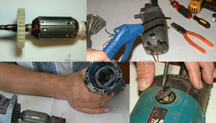
Step-by-step diagnostics of an electrician with a multimeter or a light bulb
When diagnosing and repairing the electrical part of the grinder, it is most convenient to use a multifunctional tester (abbreviated name is a multimeter).If such a device is not at hand, then a screwdriver with an indicator or a light with two wires is suitable for some checks. During the repair process, the multimeter allows you to measure both the voltage and current values, and the resistance of the motor windings. The indicator and light can only indicate the presence or absence of voltage.
Power failure diagnostics
Perhaps the most common malfunction of a grinder's electrical equipment is a break in the power wires inside the sheath of the power cable. To diagnose and repair such damage, it is enough to disassemble the rear handle of the grinder and check the voltage at the terminals in front of the switch. Another way is to disconnect the cable terminals and use a multimeter to check the resistance of each wire for an open.
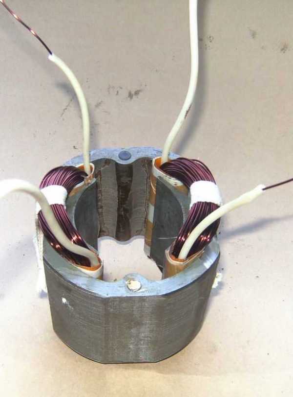
Checking the stator and rewinding it
To check the stator of the grinder's electric motor, it is necessary to disconnect both of its windings from the power circuit, and then measure their resistance with a multimeter in the range of 200 ohms. On a serviceable winding, the device will show a resistance of about one ohm, and on a faulty one (with a break) - tens or hundreds of ohms. If the winding fails as a result of a short circuit, then carbon deposits can usually be seen from the inside of the stator housing. Check stator for turn-to-turn closure it is impossible with an ordinary tester - there are special induction devices for this. The only way to repair the stator is to replace or rewind it. The second is possible only with the appropriate qualifications, therefore, most often the stator is simply changed.
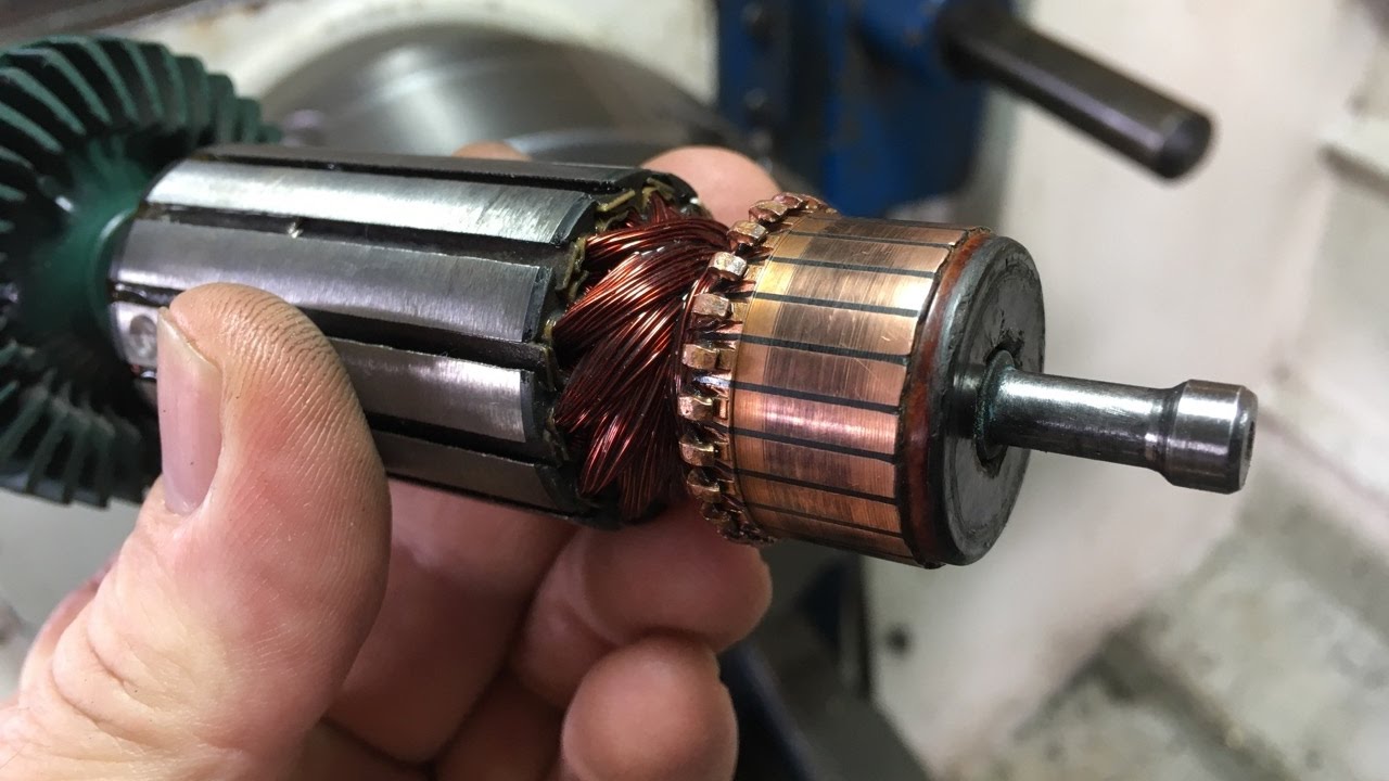
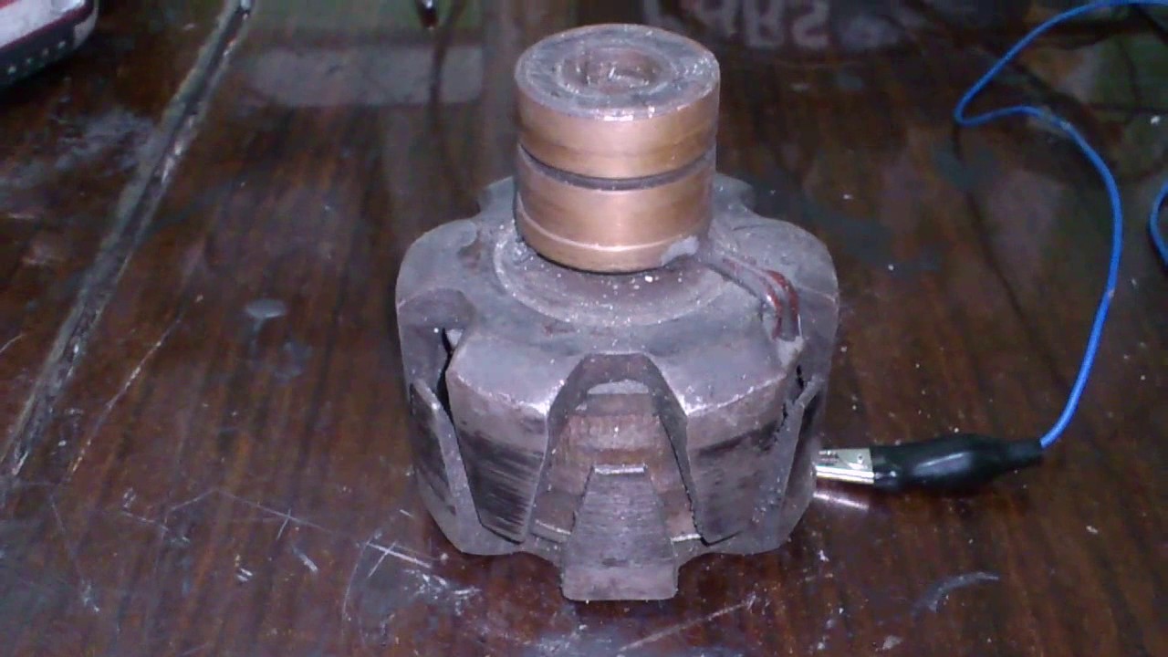
Diagnostics of the anchor by the tester
It is necessary to check the anchor of the grinder for both the breakage of the windings and their short circuit to the core. In the first case, the resistance is measured in a circle between two adjacent collector plates located on the rotor shaft. All values should be the same (within one ohm), and a significant difference indicates an open circuit. In the second, the measurement is made between the rotor magnetic circuit and the collector plates. To search for an interturn short circuit, as in the case of the stator, you must use a special device. If a malfunction is found, it is necessary to decide in what way to make the repair: by rewinding the anchor or replacing it with a new one. It is unrealistic to rewind the armature windings on your own without the appropriate skills and equipment, and rewinding in the service will cost almost the same as a new anchor. Therefore, the best repair option is the purchase and independent replacement of the anchor.
Checking the start and control unit
Diagnostics of the electronic components of the grinder is reduced to determining the health of individual units, and repair (if there are no skills in radio engineering) - to their complete replacement. The soft starter can be checked with a pointer ammeter, comparing the current surge with and without it. An oscilloscope is required for accurate diagnostics of the load control unit. Although, in order to understand whether it is serviceable in principle or not, it is enough just to observe the behavior of the grinder in different modes.
Checking carbon brushes
In the process, the carbon brushes are erased and must be replaced when the minimum size is reached. The first sign of a problem with the brushes is an irregular spark ring around the manifold with bursts. Some models have round holes with screw caps for replacement and inspection of brushes. But for most grinders, in order to change them, you have to completely disassemble the body or the rear handle, as in a repair.
Diagnostics of the start button and the speed controller
The most common malfunction in the electrics of a grinder is the failure of the start button, which is most often the result of dust getting into it. You can check the functionality of the button using a multimeter or an indicator screwdriver by measuring the voltage at its output contact.It usually cannot be repaired and is simply replaced with a new one. Determining the malfunction of the speed regulator is even easier: when the wheel rotates, it either changes the number of spindle revolutions or not. If you don't have the skills to repair such devices, then it's easier to buy a new one for a few hundred rubles.
Mechanical breakdowns
How to repair a drill if the electrician is ok?
- The first mechanical failure is coked bearings. Dust gets into the lubricant (with faulty oil seals), and the bearings quickly fail, up to seizure. The treatment is simple - we wash it with kerosene, fill it with grease and install new oil seals. A grease is used for high-speed units, for example, molybdenum
- A more serious problem is the repair of the drill gearbox. It is good if there are spare parts (usually gears). Otherwise, you will have to change the entire module. Ready-made kits are commercially available. If your drill has a well-known name, you can find the accessories
- Another difficult malfunction is cartridge repair. Taking a look at his device, it becomes clear how to carry out repairs.
Often the internal lubricant mixes with the drilling products, after which the movable jaws become seized. The cartridge should be disassembled, rinsed in kerosene and re-lubricated before reassembly. If the parts inside the structure are badly worn out, buy a new unit.
Since gearbox failure is the most common mechanical failure, we will dwell on its design in more detail.
In addition to the gears to reduce the speed (and at the same time increase the torque), the gearbox has angular contact and radial bearings (marked with arrows).
When these components wear out, the reduction gear pair experiences increased loads. The teeth are grinded and even broken. If a hammer drill mechanism is installed, the gears live even less.
Therefore, try to use bump mode only when absolutely necessary.
In addition to the standard one, there is a planetary gearbox.
This sophisticated design is used to save space. It is practically not subject to repair, changes in assembly.

Summarize. The drill is quite easy to repair. If the node cannot be restored, it changes entirely. In any case, repairs are cheaper than buying a new device.
You can use this video as a guide to repairing a hammer drill. Everything is described and shown in detail.