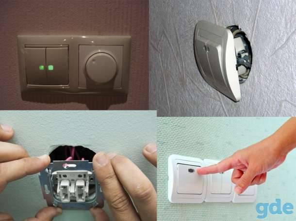
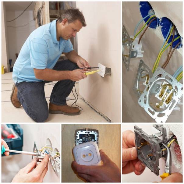
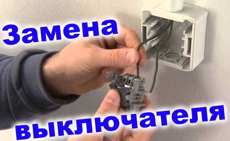
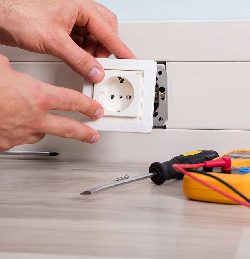
Ways to connect light switches
First of all, they are installed in the most inconvenient place, for example, in blind long corridors, on flights of stairs and other similar points. That is, at the very beginning of a long unlit corridor, the light can be turned on with switch # 1, and at the end - turned off using switch # 2. In order for such a system to work correctly, you need to know how to connect a light switch in an apartment. This operation can be done in several basic ways.
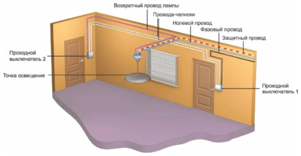
The general connection diagram, in addition to the pass-through switches, consists of a junction box, wires and a lighting device. Two, three, or four conductor cables can be used in various designs. From the power source, the zero core is fed through the junction box to the lighting device. To connect the phase wire, a common contact of any of the switches is used.
The changeover contacts in each circuit breaker are connected by separate wires, also passing through a common box. The two common contacts are connected by a separate wire that acts as a continuation of the phase conductor interrupted by these contacts.
Connecting in three places is fundamentally almost the same as a point-to-point scheme. It's just that the third switch uses a completely different design. When one key is pressed, two independent contacts are flipped simultaneously. This arrangement assumes the use of a four-core cable. In this case, no additional elements are required. The points are set in places marked in advance, after which all the elements are connected to each other according to a certain scheme.
Installation of a closed circuit breaker
At the installation site of a closed switch, there should be a cylindrical recess in the wall, usually equipped with a socket box, which is a metal or plastic cup, through the bottom of which a wire for connection comes out. Conveniently, the length of the wires for connecting the switch is 10 cm.
How to install a closed one-button switch
Whatever the switch, before proceeding with its installation, it is important to determine with the help of a voltage indicator which of the wires is energized and which is not. After that, it is necessary to turn off the power supply to the installation site of the device and re-check the presence of current on both wires
One-button switches may differ slightly from each other depending on the manufacturer and the price.
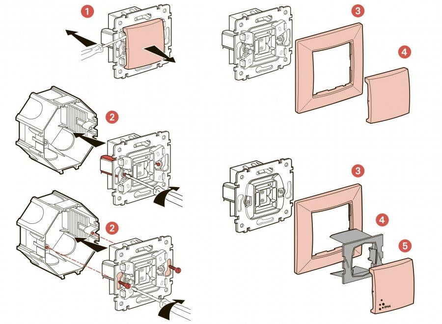
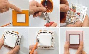
The simplest design is for devices whose price does not exceed 80 rubles. On the mechanism of such a switch there are expansion brackets for mounting, which are tightened with screws. To connect each of the phase wires, there is also a screw, to which the holes lead. The entire installation includes the following steps.
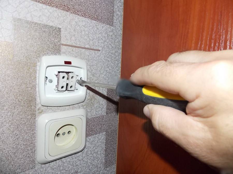
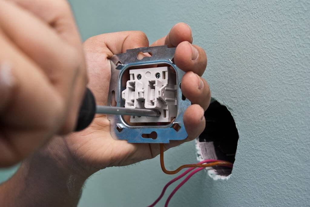
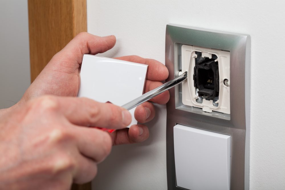
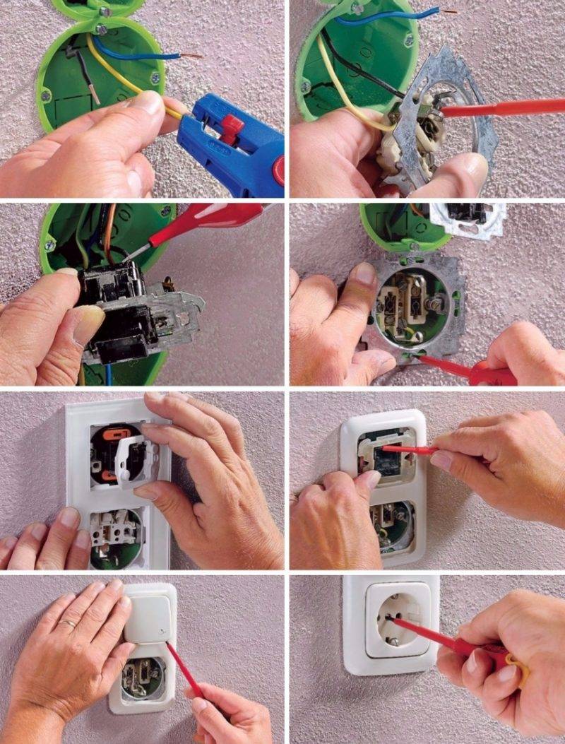
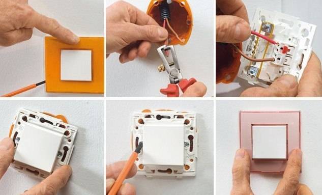
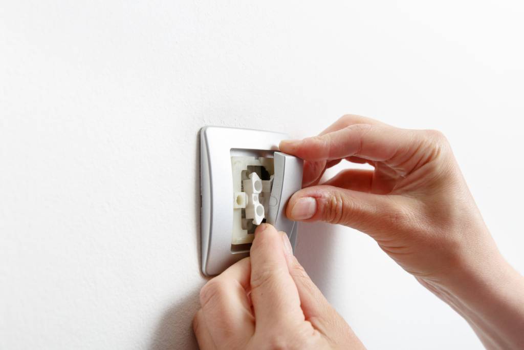
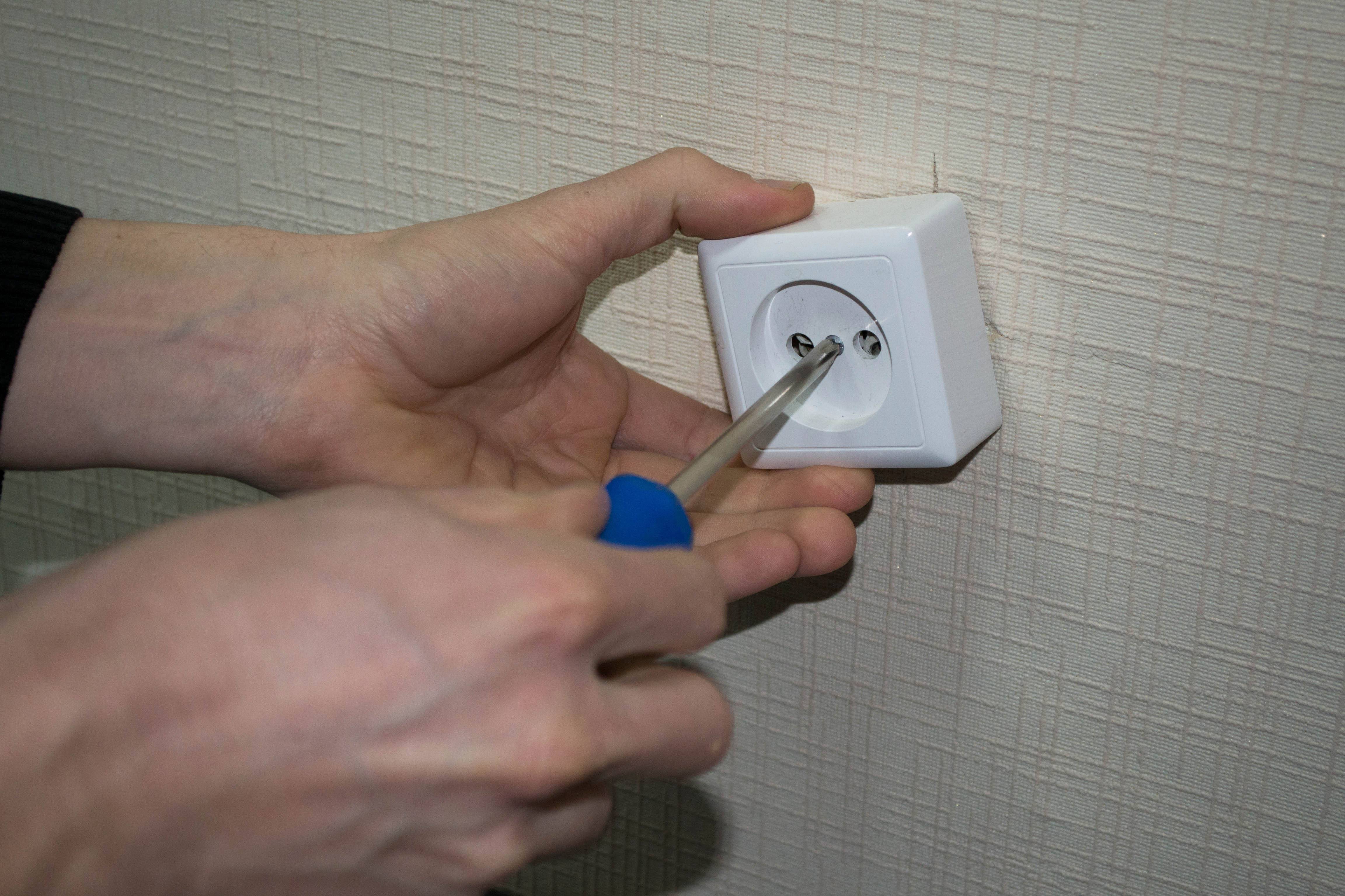
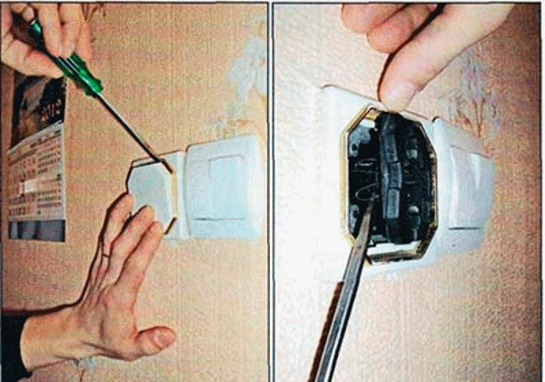
Step 1. After the phase is completely de-energized, prepare the circuit breaker itself for installation. To do this, remove the button from the frame. There are two screws under the key that connect the mechanism to the face of the switch. They are unscrewed by disconnecting the frame from the working element of the switch.
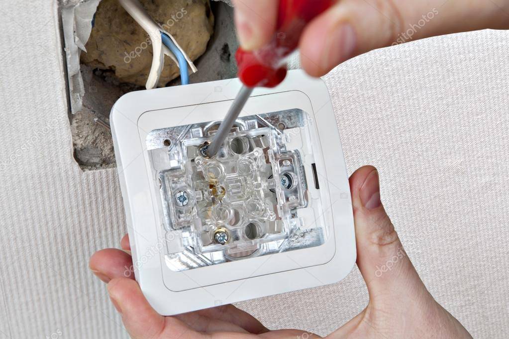
Step 2. Unscrew the screws to connect and fix the wires.
Step 3. Strip the insulation off the cables, leaving about an inch of each wire exposed.
Step 4. Insert the phase cables into the holes leading to each screw so that the bare section of the wire does not enter the groove by 1 mm of its length.
Step 5. Tighten the screws that secure the contacts and check how firmly the connection is made. The ends of the cables must not move freely.
Step 6. Now the mechanism is installed strictly horizontally into the socket.
Step 7. Fix the working element with the spacer brackets by tightening the screws that adjust the spacers. Check if the switch is securely mounted.
Step 8. Put a protective frame on the mechanism and fix it through special holes with screws.
Step 9. Install the keys.
The installation of the switch is complete.
One-key devices, the price of which is above 90 rubles, differ slightly in their design and installation process. At the very beginning, do not forget to check the active phase and turn off the power supply.
Step 1. Before proceeding directly with the installation of the switch, a special plastic socket is installed. It is mounted in a concrete wall using alabaster.
The socket has a special hole for the wire.
Step 2. Remove the key from the mechanism.
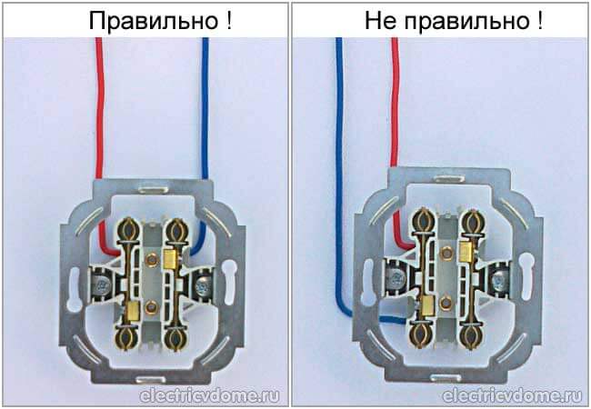
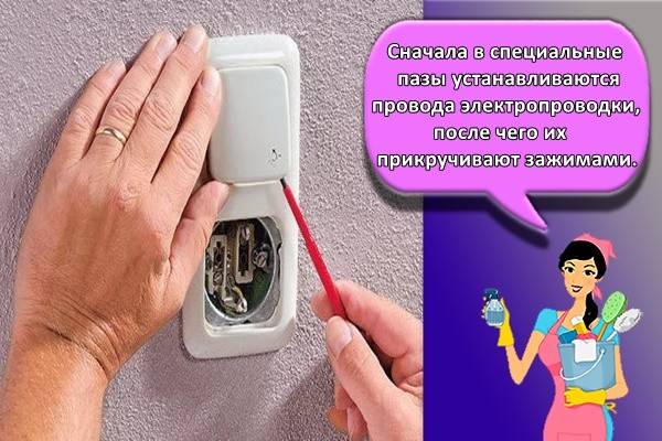
Step 3. The holes for the wires of such a switch do not have screws, but are arranged so that the contacts in them are securely fixed. For this, the wires are inserted into the slots in accordance with the pointers: L - inlet, down arrow - outlet.
After the bare contacts have been inserted tightly into the holes, it is necessary to check the strength of the connection. To do this, lightly pull on the wires. If for some reason it is necessary to pull out the cables, then press on a special lever located on the side of the mechanism.
Step 4. Mount the mechanism in the socket box strictly horizontally and fix it with screws.
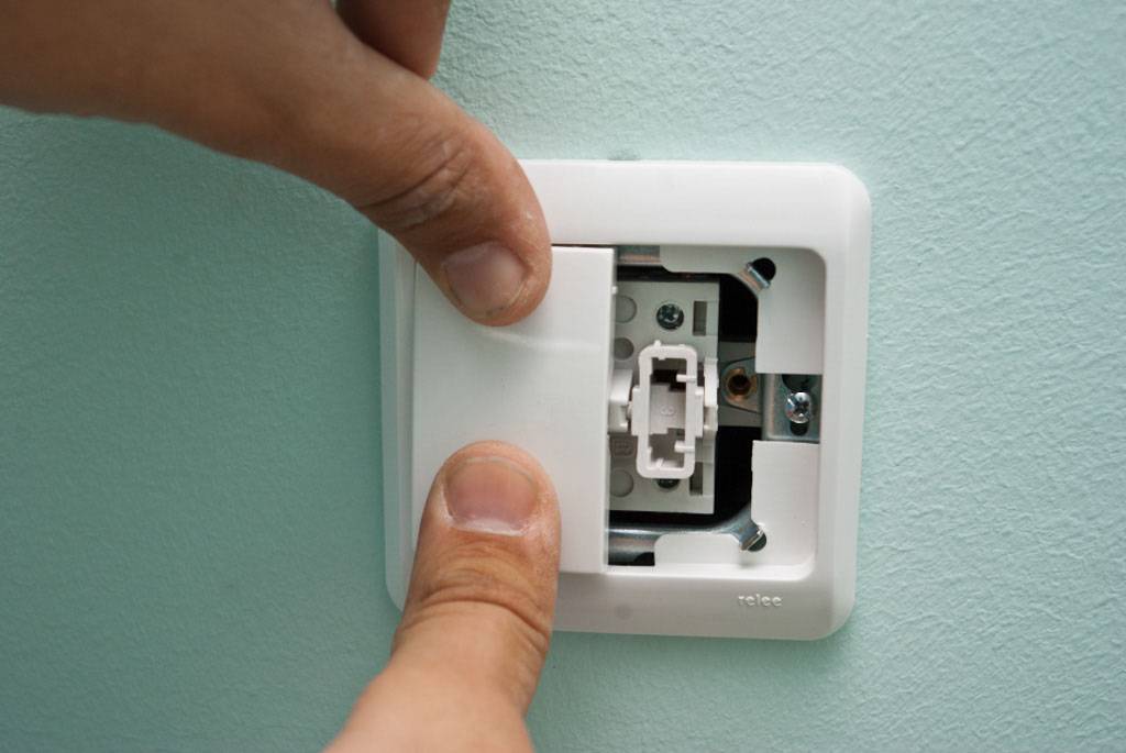
Step 5. Install and fix the frame thanks to a special latch.
Step 6. Fix the key.
The switch is ready for use.
Two-button switches and their installation
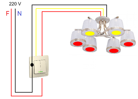
Such a device is installed to control chandeliers with a large number of bulbs or, for example, for a separate bathroom. The design and installation principle of a two-button switch does not differ much from a one-button switch.
The difference is that 3 phase wires are suitable for the switch: one is input, the other two are outgoing. Only the first cable is energized.
Cheap switches do not have designations in which groove to insert which wire. In fact, it is difficult to get confused here. There is one screw on top, so the current supply wire is connected here. The bottom slots are provided for the de-energized phase.
More modern and expensive devices on the back of the switch have the following designations:
- when we are talking only about digital characters, then 1 is the supply wire, and 2 and 3 are the outgoing ones;
- if on the mechanism there are signs L, 1 and 2 or L and two arrows, then the supply wire is connected to L, and the outgoing ones are connected to the rest.
Otherwise, the installation does not differ from one-button switches.
Wiring diagram for lighting switches from three places
In the presence of large rooms, it is advisable to use not two, but three light switches. Very often, such systems are installed in yards or in personal plots. When leaving the house, the light turns on, and after approaching the desired place, it turns off.
Three switches can be installed in rooms with multiple berths. The same scheme can be used on long unlit staircases. In this case, the walk-through switches are installed at the bottom, in the middle and at the end, at the top of the stairs.
A special wiring diagram is used to control the lighting from three different locations. It includes a junction box, lighting fixture, wires and switches. The circuit uses two pass-through and one cross-over switch. The appearance of these devices resembles traditional one-button switches. The essential difference is not the complete disconnection of the electrical circuit connections, but only the switching of contacts from one position to another. In pass-through switches, the switching mechanism is located in the middle of the contacts.There are two-rocker switches that combine two single-rocker switches and are equipped with six contacts.
One-key switches have three contacts: one for the phase conductor and the other two for intermediate conductors. The cross switch has four contacts, from which two wires run to each toggle switch. Switched electrical lines are connected in the shape of a cross, hence the name of this device. During its operation, the first and second switches are simultaneously connected and disconnected. As a result of moving the contacts, the light turns on and off. When any pass-through switch is turned on, the intermediate electric wire closes. A closed circuit is formed and the light comes on. If you change the state of any key, the light will go out.
When installing the system, you need to pay attention to the correct connection of the ends of each conductor. Otherwise, the circuit just won't work.
Correct wiring in the junction box with a large number of control points is especially difficult. It is recommended to mark the wires at the stage of laying, so as not to confuse them in the future when connecting.
Preparing to connect
Before connecting a new device, you need to prepare it for installation. The procedure is as follows:
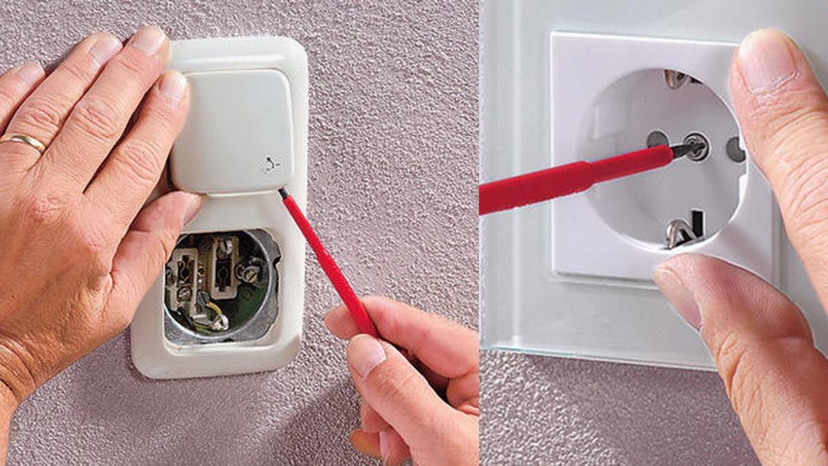
- Remove the key using a flat screwdriver.
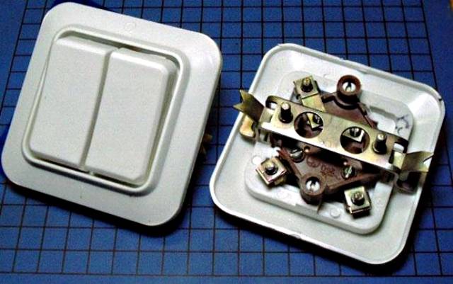
- Unscrew the screws to gain access to the mechanism. The design of these devices is different, but they are connected according to a single principle and are fixed to the socket by means of spacer legs. The movement of the latter is provided by screws.
A pair of screw clamps and a pressure plate are provided to fix the wires. With their help, you can loosen the fastening, or, on the contrary, press the veins more strongly. Each contact can be connected from one to two cores.
What to do if the switch needs to be moved
In some situations, there is a desire or need to move the switch to another location. For example, when there are children in the family who have already grown up, but still cannot reach the top switch. Therefore, according to the rules for the installation of electrical equipment, it is allowed to transfer the device to another place.
 The benefits of replacing the circuit breaker yourself
It is allowed to mount the switch at a distance of 82 to 165 centimeters from the floor level. Nevertheless, in order to start work on the transfer of equipment, you must first determine the exact location of its installation. It is recommended to place the switch at a distance of no more than 25 centimeters from the door jamb (the side is not important, but more often the device is placed on the right).
 It is allowed to install a switch on each side of the door.
Moving the circuit breaker - step by step instructions
Step 1. If you move the equipment within 100 centimeters from the existing position down or up, then a strobe is made in the overlap. As a rule, it has a depth of 2 times the cross-section of the cable in the corrugation. So, the wire should not stick out from the opening. You can prepare such a recess with a puncher or a special tool for strobes.
Prices for popular models of wall chasers
Wall chaser
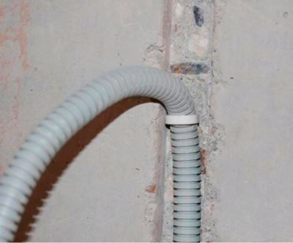 This is what the strobe looks like in the overlap for the cable
Step 2. Now, directly at the installation site of the new switch, you need to make a recess for the mounting cup. This is done using the same perforator and a special round nozzle. If the wall is concrete, then the depth of the opening will be about 50 millimeters, and if it is brick or panel, then 45 millimeters. The diameter of the nozzle itself will be about 7 centimeters (selected individually).
 This is what the opening for the mounting bowl looks like.
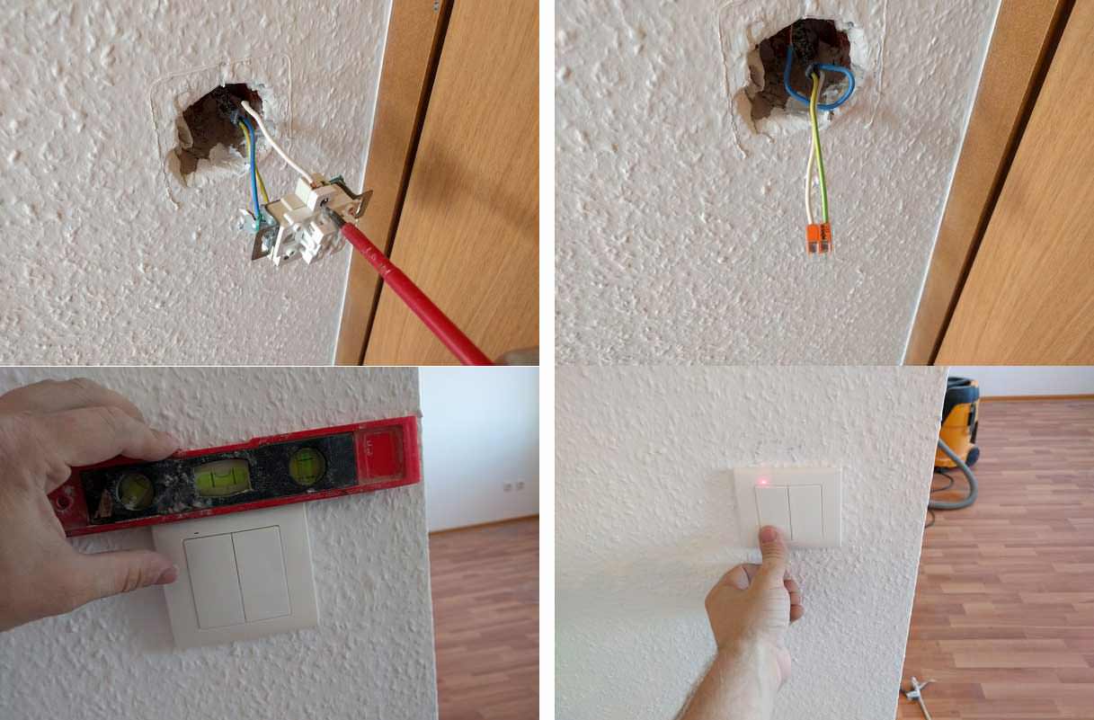
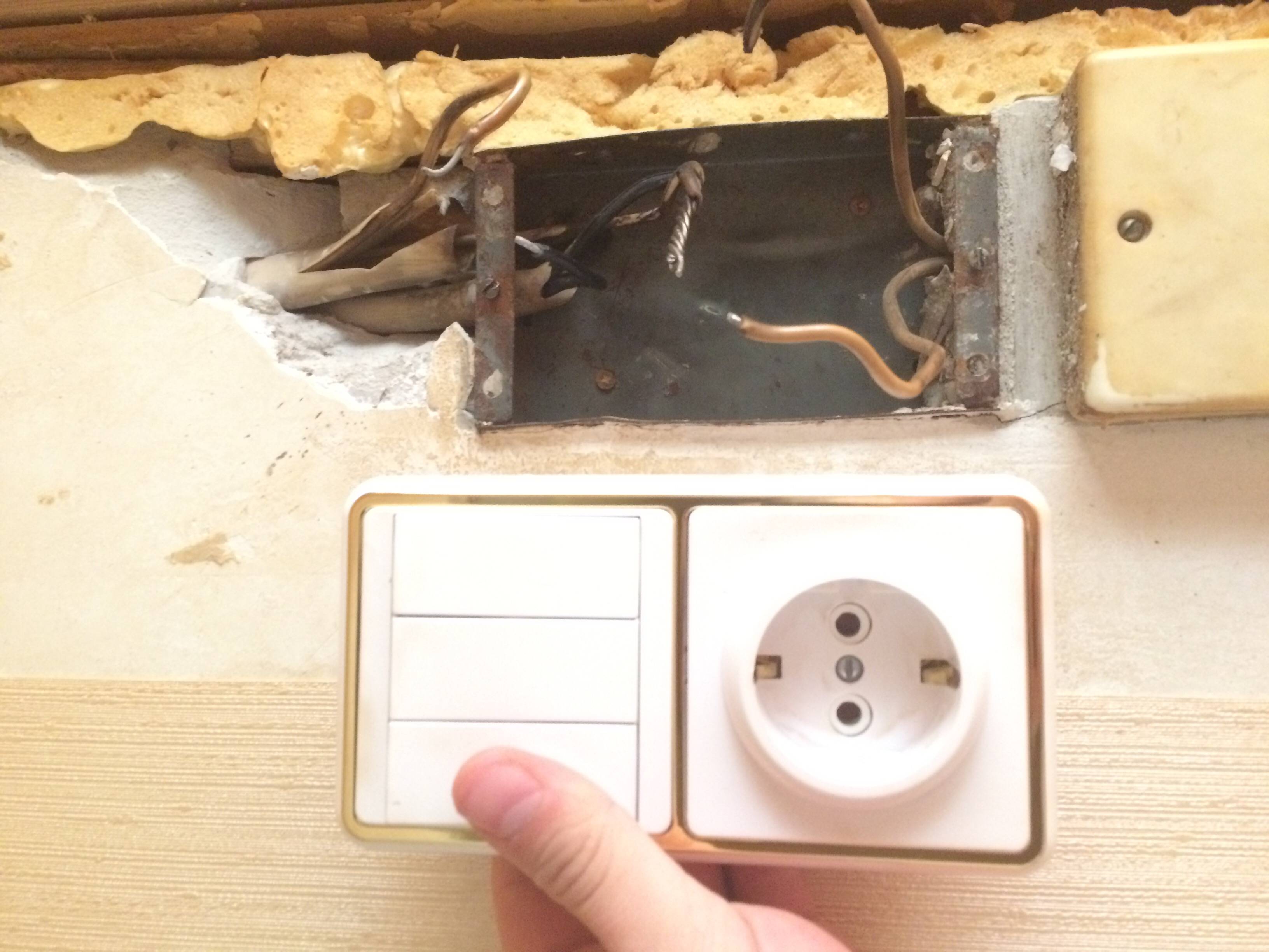
Step 3. Now you need to completely de-energize the apartment and dismantle the old switch (in the way that we discussed above).Only here, in addition to the switch, the mounting bowl is dismantled from the wall. To do this, you need the same percussion apparatus or a hammer with a flat screwdriver. Most often, the sockets are fixed on a gypsum solution, which begins to crumble upon impact
In this case, it is important not to violate the integrity of the plastic base.
Carefully remove the mounting cup from the wall
Step 4. Now you should extend the cable to the required length. The wires, as a rule, are connected with special clamps or a block, but if this is not possible, then their ends are bumped together and then insulated. According to the installation rules, the cable must be in a special plastic corrugation with a diameter of about 1.6 centimeters. It is also necessary to wrap with insulating tape the joints of the two parts of the corrugation. When lengthening the cable, leave a few centimeters in reserve.
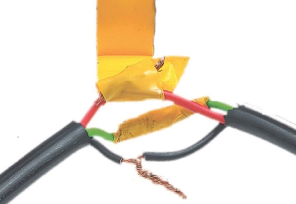 There should be no exposed wires, so they are wrapped with insulation tape
Step 5. Now you need to install the mounting bowl in the new opening, it will be easier to fix it using alabaster, which contains plaster. Since the plaster begins to harden in a few seconds, it is quickly diluted with water according to the instructions, and then the hole is covered.
 It is necessary to work with alabaster quickly, until it has time to harden.
Step 6. It is also necessary to cover up the grooves in the ceiling with a solution. In this case, the wiring should be laid according to all the rules, because it will no longer be possible to change its location. Then the surface of the wall must be finished with a finishing putty in order to finally hide the location of the strobes. When the surface dries, it is treated with fine-grained sandpaper.
Prices for popular types of putty
Putties
 The strobes should also be putty
Connect the switch only after the solution has hardened. Therefore, you will have to wait a few hours.
If you plan to move the switch a considerable distance from its original location, then most likely it will need to be connected to a different box. In this case, it is advisable to seek help from an experienced electrician.
Nuances when disassembling various types of switches
Three-button switches are often used to power a large number of spotlights, ceiling lighting and other lighting devices. The design of such models is distinguished by rather thin keys. But, as with two-key switches, dismantling a three-button switch begins with removing each one one by one. Many models are equipped with a small rectangular hole at the bottom of the keys to simplify this procedure, into which a screwdriver can easily enter.
If you want to disassemble the dimmer (adjustable rotary knob switch). Then its dismantling is fundamentally no different from the classic model, with the only difference that instead of keys, you first have to remove the knob.
The touch switch is disassembled by removing the outer panel
For this purpose, you can use either a regular screwdriver or a special pickup, which you can make yourself from the wire, if it is not included in the kit. At the same time, you need to be very careful not to crack the glass.
If the switch is paired with a socket, then to dismantle the first, you will need to remove the socket along with it. In this case, the outlet cover will have to be removed, since one of the fastening bolts is often hidden under it.
Pass-through switches have the same design as conventional ones, and, accordingly, the same disassembly procedure
The only difference is the number of wires, since the phase is connected in several positions at the same time.
Why are pass-through switches needed?
These switches are most commonly used in the following locations:
- on the stairs. You can install switches on the 1st and 2nd floors. At the bottom we turn on the light, go up the stairs, turn off at the top.For houses more than two stories high, additional switches can be added to the circuit;
- in the bedrooms. We install a switch at the entrance to the room, and another one or even two near the bed. We entered the bedroom, turned on the light, got ready for bed, lay down and turned off the lighting with the device installed near the bed;
- in the corridors. We install on the switch at the beginning and at the end of the corridor. We go in, turn on the light, reach the end, turn it off.
The list can be continued for a very long time, because almost every situation has its own variant of application of the pass-through switch system.
How to get started?
To get started you need:
- decide on what type of switch you need to install;
- prepare the tools and materials that will be required.
Selecting a new circuit breaker
When choosing a device, you should pay attention to the following parameters:
- Ultimate power. This device parameter is calculated using the simplest mathematical formula. This indicator determines the permissible load, and it is especially critical when using conventional incandescent lamps. The total power consumption of the luminaire should not be higher than that indicated on the switch. If only the allowable current in amperes is marked on the case, the maximum power can be calculated by multiplying this value by 250. For example, 6 A × 250 V = 1500 W or 1.5 kW. It is recommended to use LED bulbs to reduce power consumption.
- Body material. It determines the thermal stability of the device. Large rooms with powerful luminaires will require breakers that can handle heavy loads. The type of housing in which the contacts are located is important here. It can be made of ceramic or plastic. Ceramic housings are immune to temperature extremes, they work properly, even if a large current flows in the circuit. For an ordinary apartment in a multi-storey building, a breaker with a plastic case is suitable.
- The number of keys on the switch. The number of buttons is selected based on the type of luminaire, the capabilities of the existing wiring and connection diagram. In the kitchens of ordinary apartments, devices with one key are most often used, and in living rooms with two. Also, two-button devices are used in separate bathrooms.
- Mount type. For internal switches, the body is hidden in the wall, and on the surface there is only a cover with a socket. Outdoor switches are almost never used in modern apartments. Their distinguishing feature is their thick body and exposed wiring (not hidden in the wall) connected to the device. Illuminated switches are most often installed in the corridors at the entrance to the apartment, so as not to look for them in the dark.
For bathrooms, you need a device with a moisture resistance index of at least IP 44, and when installed outdoors (for example, in a private house) - IP 55 and higher.
Tools and materials for work
To change the switch you need to prepare:
- indicator for finding a phase wire;
- a powerful flat or curly screwdriver;
- wire cutters or pliers;
- a knife for stripping the cable.
Connecting multiple lamps
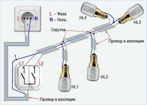
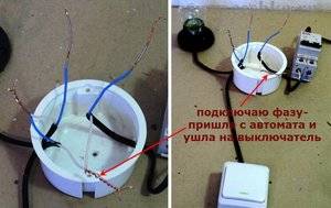 You can connect two bulbs to one switch. To do this, they need to be connected in parallel and connected to the wire leading to the luminaire. The number of lamps with this connection is limited only by the rated current of the switch itself, but all lamps will turn on and off at the same time. Separate operation requires the use of other switching elements.
If, for ease of use, you decide to install a backlit switch, then there is one point to consider. Many modern energy-saving and LED-based lamps will flash periodically with this scheme, and you will have to either change the lamps or turn off the backlight.
In conclusion, I would like to remind once again about the strict observance of safety rules at all stages of the work.
Pay special attention to the reliability of the connection of the conductors and the insulation of these places.
Removing the switch
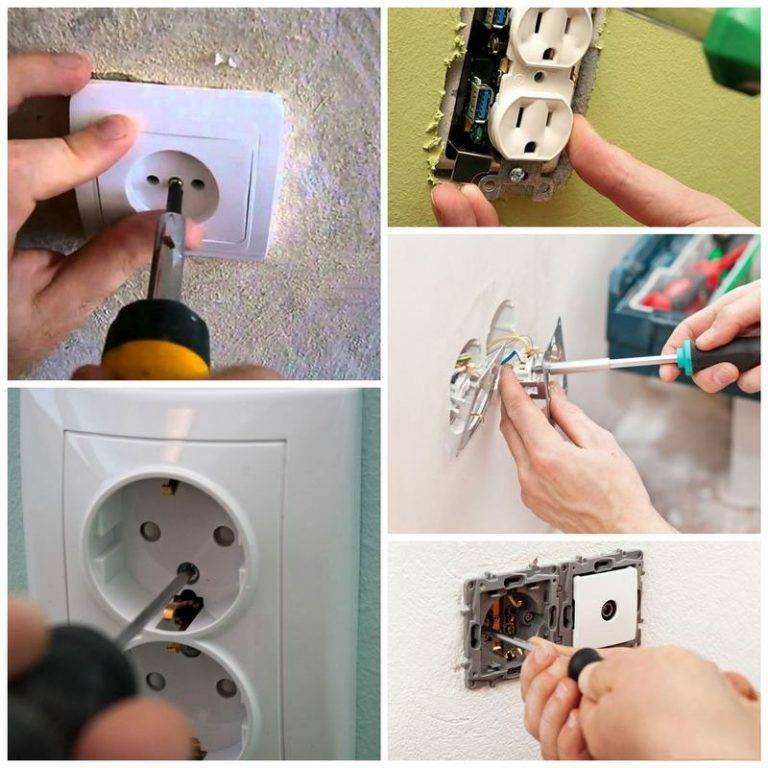
To dismantle a faulty device, you must first remove its protective cover, made of plastic or carbolite. To do this, you need to unscrew the 2 fastening screws.
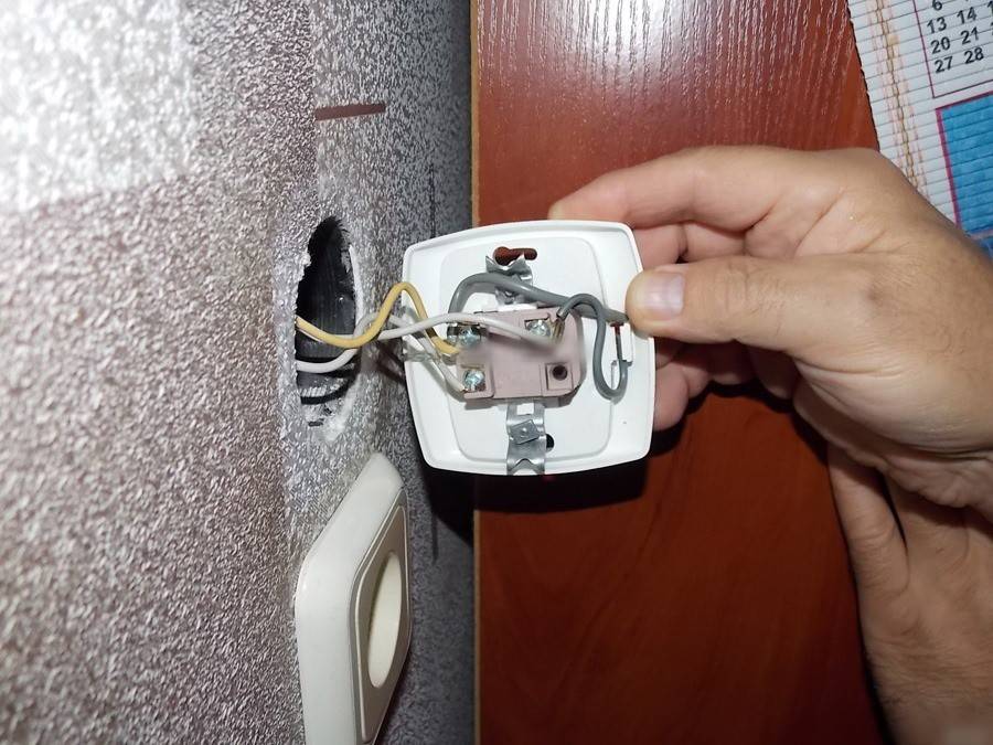
The one-button switch mechanism is fixed inside the socket with spacer lugs. It has a pair of screw terminals with cable conductors connected to it. The position of the feet can be adjusted, if necessary, with the screws on the left and right sides.
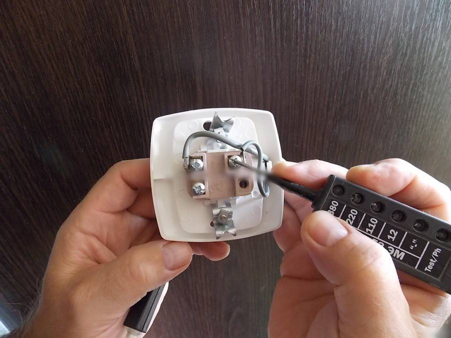
Before removing the mechanism, you need to determine which vein the phase approaches to it. For this we need a probe screwdriver. Touching her contacts one by one, we check the presence of voltage. Then the device key should be switched to another position, after which it should be checked again.
Phase detection is performed on a live circuit breaker, so you must be extremely careful when performing this procedure. Only after its completion, the room must be de-energized by turning off the switch or unscrewing the plugs.

After de-energizing the apartment, you need to make sure that there is no voltage at the switch, and then continue to dismantle it. In this case, you need to proceed as follows:
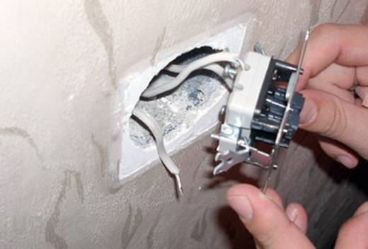
- Remove the mechanism from the socket after unscrewing the screws of the spacer lugs.
- After that, you need to separate the wires, starting with the phase one. Unscrew the contact screw, pull out the cable and mark it with electrical tape.
- Disconnect the second cable from the mechanism.
- Straighten the wires.
This completes the dismantling.
Description of the connection process
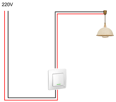
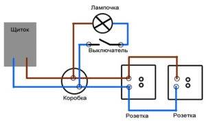
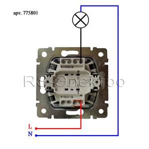 Now let's look at how to properly connect a light switch from scratch. The connection diagram for a one-button switch is simple. In order for the lamp to light up, two wires are connected to it - phase and zero. In order for the light to be turned off, you need to cut one of the wires and connect a switching device to this gap.
When replacing bulbs, you can touch the live part of the socket and get an electric shock. To avoid this, always install the switch in the phase wire break.
Regardless of the installation method, in practice it looks like this.
- The main cable is laid, which goes from the power source to the luminaire. It is located on the wall at a distance of 150 mm from the ceiling.
- The wire from the switch is run vertically upwards.
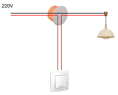
- At the intersection of the supply wire and the wire coming from the switch, a junction box is installed, in which all the necessary wire connections are made.
Now you can start assembling the circuit. We will make the wiring with a two-core cable. For the convenience of performing this operation, the length of the wires coming out of the box is made such that their ends come out of it by 20 centimeters, the same length is made for the wires that will connect the rest of the circuit elements. The ends of the wires are stripped of insulation. The connections are made in the following sequence:
- Spread the ends of the wire coming from the network so that they do not touch each other. Apply voltage to this wire and use an indicator screwdriver to determine where the phase is. It is imperative to put a mark so as not to confuse it with others in the future.
- We turn off the power.
- Connect the neutral wire of the supply cable to one of the wires going to the luminaire.
- Connect the phase wire of the power cable to either of the two wires coming from the switch.
- We connect the two remaining wires (the wire from the switch and from the lamp).
- We randomly connect the wires to the switch.
- We connect the wires to the lamp holder. It is desirable that the wire coming from the switch be connected to the center contact of the socket.
- We supply power and check the functionality of the circuit. If everything is okay, carefully lay the ends and close the junction box.
- We install the switch in the back box.
Connection diagram for lighting switches from two places
Conventional switches installed in rooms provide switching on or off the light from only one place. However, situations often arise when it would be more convenient and comfortable to control light from different points of an apartment or house. This is especially true for flights of stairs and long corridors where there is no natural light. That is, at the beginning of climbing the stairs, the light is turned on by the first switch, and at the end, it is turned off by the second.
This problem is successfully solved by the lighting connection scheme in the apartment with two light switches. Thus, not only the ease of use of lighting devices is achieved, but also significant energy savings. To install the switches, it is necessary to pre-lay a three-core cable to the connection point, purchase two pass-through switches and a junction box.
When using the simplest circuit, the neutral wire runs from the shield to the junction box, in which it is connected to the neutral conductor connected to the lamp. The connection of the switches themselves is carried out through the box using a three-core cable. To bring the phase to the switches and then to the lamp, a single-core wire is used. When three or more light switches are connected, the number of cores in the cable increases accordingly to four, five, etc. Thus, the installation of a double pass-through switch is not particularly difficult. You just need to carefully observe and control the sequence of connecting the conductors.
The effectiveness of light control can be assessed using the example of a long dark corridor illuminated by two lamps. At the very beginning of movement along this corridor, the light is turned on by the first pass-through switch. After a person is in the right place, for example, near a kitchen or bedroom, the lighting is turned off with a second switch. That is, to turn off the light, you do not need to go to the switch at the beginning of the corridor and then go back.
As another example, consider a bedroom in which the light is also controlled by walk-through switches. In this room, the first switch is installed in the traditional place near the door, and the other near the bed. Thus, in order to turn off the light, you do not need to get up and go to the door.
What do you need to know when replacing a breaker?
When replacing a switch with your own hands, you need to know that:
- The voltage in the electrical network is a danger to humans, therefore, you should not touch bare, unpowered wires with your bare hands.
- Before starting work, you must study the instructions for each specific model.
- For those who are doing their own replacement of electrical appliances for the first time, it is better to take photographs of the key points. Even a small deviation from the algorithm can lead to unpleasant results, such as damage to lights or wiring due to a short circuit.
Types of switches
The switches differ from each other in:
- the way of fastening to the wall;
- the number of keys;
- design features;
- the type of connectors for connecting electrical wires;
- the principle of inclusion.
Devices can be produced in a conventional design or protected from moisture penetration. The latter are intended for use in bathrooms or outdoors.
By fastening method
By the method of fastening, the switches are subdivided into:
- Internal devices. They are installed in special recesses in the walls, often in conjunction with socket outlets made of metal or plastic. This is the most common type of device used in multi-storey apartment buildings.
- Outdoor. Used in conjunction with exposed wiring and mounted directly to the wall.
By design
Depending on the purpose and design features, the switches are:
- keyboards;
- push-button;
- rotary (slide).
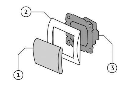
The design of a simple switch with one key: 1 - a key with which the mechanism is driven; 2 - decorative frame; 3 - the working part, which contains the electrical mechanism
By the design of the terminals for securing the ends of the wiring
Modern circuit breakers use two types of terminals for fixing electrical wires:
- Screw. Connections where the clamp is made with screws loosen over time, which leads to an increase in temperature at the point of contact and burnout of the cable. They must be examined at least once every 2-3 years and tightened.
- Spring loaded. Such terminals are more durable and provide reliable contact throughout the entire period of operation.
On the principle of inclusion
Modern switches on the principle of inclusion are:
- mechanical - elementary key devices, easy to install and use (the function of a key can be performed by a lever, toggle switch, button, cord, rotary knob);
- electronic sensory, hand-operated;
- with remote control, equipped with a remote control or a motion sensor.
Photo gallery
Principle of operation
The principle of operation of the switch is that there is a movable contact inside the element mechanism. When you press a key, it can take one of two positions. The first position is “on”, the second is “off”. In this case, the movable contact will either connect the circuit or disconnect it.
The movable contact closes the circuit, and the phase is sent along the wire provided for it to the lamp of the luminaire. As a result, the lamp starts to glow.
Varieties of switches
Manufacturers release a large number of different switches, they differ from each other in many ways. In order to understand, we will consider them in more detail.
Table 1. Types of switches according to the method of connecting wires.
| View | Description |
|---|---|
| With clamp and screws | To connect the contacts in such a device, a clamp is installed, which is fixed to the screws. The installation of this connection is complicated, but a high-quality contact is obtained. Of course, over time, the connection looses, then you have to tighten the screws. It is believed that this method of connection is suitable when aluminum wires are present. |
| Mechanisms with springs | This is a modern version of the screw clamp. Here, under the spring, there is a special plate that fixes the bare wire. Thanks to this, a high-quality connection is obtained. However, this is a rather primitive way of editing. The downside of the design is that the wire must be clamped in accordance with the rules. Otherwise, the device will be defective. These switches are compatible with copper wiring. |
Table 2. Types of switches according to the installation method.
| Type of | Description |
|---|---|
| Overhead | So it is customary to call devices that are first applied to the wall, and then fixed. They look less aesthetically pleasing because they stick out. Often such devices are used with external wiring. At the same time, the devices differ in functionality, ease of installation. |
| Built-in | For such switches, an opening in the wall is prepared in advance. Because of this feature, installation is complicated, but in the end the device will look aesthetically pleasing. Only the outer panel can protrude slightly from the wall. Such devices are suitable for hidden type wiring. |
Table 3. Varieties of switches by management method.
| View, illustration | Description |
|---|---|
 With keys With keys
|
These devices consist of contacts that are inside and a swing mechanism with a spring. The first version of such a device is a mechanism with a ball, which moves when pressed. The second option is a spring-loaded frame, which also rolls from side to side. Such switches can have one or several keys. They differ in long-term operation with proper installation. |
 Cord type Cord type
|
Such devices were at their peak in 1975. At the same time, they are installed on modern lamps of various types. So, a strong cord comes out of the switch case, which you just need to pull to turn the device on or off. This lace is fixed on a special lever that interacts with the pivot block. |
 Sensory Sensory
|
The operation of these devices occurs without mechanical stress. In order to turn on or off the switch, you need to touch your finger to the panel, which is located on the outside. The sensor element reacts to touch, thereby sending a signal to the electrical circuit. This signal is converted into a special command. |
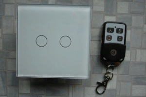 Remote controlled Remote controlled
|
Such a device assumes the ability to control the lighting device from a distance. This happens due to the presence of a special remote control. In this case, the switch acts as a receiver. The remote control is a kind of small plastic keychain. The distance of its performance will also depend on the materials from which the floors are made. However, the signal is received even at a distance of 18 meters. |
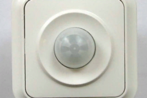 With built-in sensor With built-in sensor
|
As a rule, these devices react to certain changes around. Most often this is the movement of a massive object, which is why a signal is sent to the controller. These are programmable switches. Therefore, the user can independently decide under what circumstances the device will turn on. |
Conclusions and useful video on the topic
The process of disassembling and repairing a conventional switch with two buttons is presented in this video:
Here you can get acquainted with the device and the features of disassembling the touch switch:
This video shows the disassembly and rotary switch design:
Correct disassembly of the switch is an important step in the repair of the device. You need to remember about safety measures, and also carefully memorize or photograph each step of this process so that reassembly can also be performed without problems.
Do you have experience in disassembling a switch? Or want to ask questions about a topic? Please comment on the publication and participate in discussions. The feedback block is located below.
How to change a light switch in an apartment step by step with your own hands: with one key or two buttons, schemes and tools for replacing yourself
Fan connection diagrams in the bathroom - errors and rules for installing the hood switch in the bathroom

One key light switch connection

How to connect a double switch for two lights - wiring diagram
How to properly connect the switch from the outlet
How to connect the switch from the outlet

