Where is the best place to install the equipment
The ideal option would be to select a location for the installation of the collector during the design of the heating system. If the building has several floors, space is allocated for a manifold block on each. Most often, a niche in the wall is arranged under it, located at a low height from the floor. It should be located in a room protected from excessive moisture. This can be a pantry, a corridor, etc.
The device can be mounted directly to the wall if it is installed in a utility room, or housed in a dedicated manifold cabinet. The cabinet is a metal box with a door and a stamping for piping in the side walls. Inside the equipment, special mountings for the manifold block may be provided. You can find an invoice or a built-in cabinet version.
A well-installed manifold distribution of hot water heating guarantees the reliability and efficiency of the system. The likelihood of leaks, thanks to the small number of connections and tees, is minimized. Concealed wiring is also possible, which does not violate the aesthetics of the room. And besides, you must agree that it is very convenient to regulate the heating temperature of each radiator and the entire room as a whole. A reliable system will be a real boon for those who value their own comfort.
Hydro arrow and solar collector
Gidrostrelka and solar collector are devices that perform functions similar to plumbing combs - they collect a carrier from several sources in one case and distribute it along circuits for various purposes.
The hydraulic distributor is installed in cases when significant volumes of heat carrier are used for heating, associated with a large number of circuits and areas of heated rooms. A boiler, a hydraulic accumulator, collectors of heating radiators and underfloor heating, a boiler, pumping equipment with the installation of a circulation pump on each collector link are connected to the riser hydraulic arrow.
The device is designed to stabilize the pressure and equalize the temperature in the connected circuits, provides the convenience of connecting the distribution units. Hydrostrelka is a vertically (sometimes horizontal installation) located container (large diameter pipe) of circular or rectangular cross-section with welded side fittings, in the upper part of which there is a valve for air release, and a valve for draining the coolant is mounted below.
Rice. 12 Flat plate solar collector
Solar panels are used in areas with a large number of sunny days per year, and solar collectors for additional heating of the coolant used for heating and other economic purposes are also used to save energy.
If solar panels convert ultraviolet radiation into electrical energy, then solar collectors are designed to heat the coolant, which is air or liquid.
The simplest and most popular collector device in everyday life is designed and operates as follows. A heat receiver is placed in a metal case under a protective glass - a black plate with a pressed-in copper or aluminum coil covered with a black absorbent, the solar radiation receiver is located on a layer of insulation. The cooled heat carrier moves along the coil with the help of the heating system circulation pump and, after being heated by solar radiation, enters the boiler.
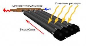
The described system has high heat losses, therefore, in more expensive schemes, a pipeline covered with an absorbent layer is used, which is placed in a vacuum.Externally, the device resembles a row of glass flasks with evacuated air, inside which are heated copper pipes with refrigerant, each pipe is connected to a solar distribution collector. In such systems, a special refrigerant with a low boiling point is used as a heat carrier; when heated, it turns into steam and transfers its energy to the carrier flowing in the heat exchange collector.
Fig. 13 Vacuum solar collector - principle of operation
Principle of operation
The heating unit can be connected to both classic radiators and warm floors. The difference will only be in the location of the collector, and not in the principle of operation. So, in any case, the collector system serves to distribute water flows across all heating devices, and this is achieved by the peculiar structure of the collector and connecting pipes to it in the future.
An important limitation is the need to be able to maintain the temperature. It should not change significantly when it gets into the pipes. For example, for a "warm floor" system, a temperature of 40-50 degrees will be sufficient, and for radiators - 70-80 degrees. The collector must be rated for at least a suitable temperature. When connected to both a radiator and “warm floors”, it should be possible to dilute the hot water with cold water or otherwise lower the temperature below, without affecting the overall flow.
Calculation of collector heating
The homeowner does not need to calculate the parameters of the collector (its bore diameter, length, cross-section of outlet fittings) and pipe diameter when purchasing a standard product. If you want to make such calculations, you can find the necessary formulas in the network, although in this case it is easier to focus on the standard dimensional parameters of manufactured factory products.
The main task of the calculations is to determine the length of the pipes to ensure the required temperature in the room with the known temperature characteristics of the coolant. To do this, there is no need to resort to complex engineering calculations, which can only be done by narrow specialists in the field of heating; for an ordinary person it is easier to use an online calculator or a computer program.
To obtain the desired result, the initial data on the required temperature in the room and its area, the diameter and pitch of the pipes, and the temperature of the medium are entered into the program or calculator. On the Internet, you can find reviews of programs for calculations Audytor CO from Sankom, Valtek Complex from the company of the same name, Raucad / Rauwin 7.0 from Rehau.
Rice. 17 Assembling the manifold block
Assembling the factory manifold
Let us first consider, with a specific example, what a ready-made distribution unit from the manufacturer consists of.
Table 1. Assembling the factory manifold.
| Steps, photo | A comment |
|---|---|
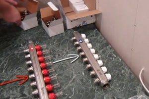 Step 1 - unpacking the assembly parts Step 1 - unpacking the assembly parts
|
This manifold assembly is called ready-made only because all the necessary elements, selected according to the optimal parameters, have already been assembled. He himself is in a disassembled state, and all the details still have to be put together. |
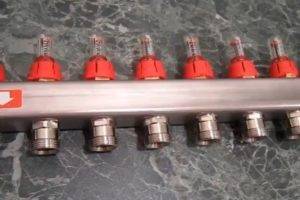 Step 2 - feed comb Step 2 - feed comb
|
This is a feed comb, each outlet of which is equipped with a flow meter (red gauge on top). Through it, the temperature range in the circuits is set. It is on this comb, if necessary, that the coolant supply to the circuits is shut off. |
 Step 3 - reverse comb Step 3 - reverse comb
|
The return manifold, in contrast to the feed one, is equipped with thermostatic push-off shut-off valves. From above, they are covered with caps, on the front side of which the direction of rotation (plus and minus) is indicated, turning which you can adjust the flow manually. |
 Step 4 - servo Step 4 - servo
|
Instead of a cap, a servo drive can be installed on the valve, which will automatically regulate the flow of water. These devices are not included in the kit, but are purchased separately. |
 Step 5 - room thermostat Step 5 - room thermostat
|
The required temperature is set on the thermostat, and it already gives a signal to the servo. |
 Step 6 - ball valves Step 6 - ball valves
|
By means of taps, the heating system is turned off. |
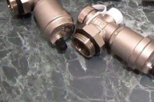 Step 7 - drain nodes Step 7 - drain nodes
|
At the end of each manifold, nodes are installed through which you can drain water from the system or bleed air. |
 Step 8 - thermometers Step 8 - thermometers
|
We don't need to explain the purpose of the thermometer. |
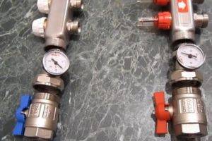 Step 9 - piping the comb from the side of the inlet and outlet of the coolant Step 9 - piping the comb from the side of the inlet and outlet of the coolant
|
On the left side of the feed comb there is an opening through which heated water flows from the boiler. First, a tee with a thermometer is screwed onto it, and then a ball valve, through which the connection to the pipeline will be carried out. The same is done on the return line. |
 Step 10 - installation of drain assemblies Step 10 - installation of drain assemblies
|
On the right, drain nodes are screwed onto both combs. |
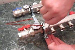 Step 11 - mounting the bracket Step 11 - mounting the bracket
|
The manifold assembly includes a bracket by means of which both combs are tied together and then hung on the wall. |
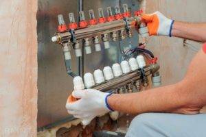 Step 12 - hanging the knot on the wall Step 12 - hanging the knot on the wall
|
The assembled unit is attached to the wall, or installed in a special cabinet. |
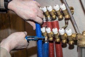 Step 13 - connecting the circuits to the manifold Step 13 - connecting the circuits to the manifold
|
It remains only to connect the supply pipeline and circuits to the collector. |
Advantages and disadvantages of radiant heating systems
Positive sides
The main advantage of the beam scheme is ease of use.
Special equipment makes climate network control as ergonomic and convenient as possible:
- You can set the temperature of each radiator in your home without leaving the manifold cabinet. In addition, if necessary, you can completely shut off the water supply to any element of the system without disrupting the operation of the entire heating network.
- Each pair of pipes connects the manifold to only one radiator. Therefore, it is possible to use pipes of small diameter, which can be easily disguised under the floor covering. Among other things, this allows you to partially warm up the floor surface.
Pipes of the radiant heating system are laid before the floor is poured
- Thanks to the use of special devices (the so-called hydrostatic arms - collectors with a large diameter), several heating zones with different coolant temperatures can be formed in the house.
In this case, a short circuit is organized between the supply and return pipes. Heated water is constantly circulating in the water gun, and its intake can be done at different distances (the temperature will also depend on this).
Negative sides
For the sake of completeness, it should be said about the disadvantages of using a radiant heating system.
It is because of them, despite all the advantages, that it is not very common:
- Strongly increased consumption of supply and discharge pipes. The more spacious the house and the more complex the geometry of the rooms, the more details will be needed. In addition, the complexity of installation increases, which cannot but affect the estimated cost of construction.
The radiant heating system requires the use of a huge number of pipes and manifolds
- The need for hidden installation. If the traditional tee system can be installed along the walls, then you cannot place a huge number of pipes in this way. They must be hidden under the floor. It can also be walled up into walls, but in this case, the consumption of material will increase even more.
- Lack of joints. When designing pipelines, it is imperative to take care that the pipe under the floor does not contain a single joint. In this place, gusts most often occur, and the cost of repairing a breakdown will be far from low and very laborious.
- If the system design provides for several circuits with different coolant temperatures, then each of them must be equipped with a circulation pump.
Self-made collector
For the manufacture of a distribution manifold, a diagram is drawn up, which takes into account all the materials used. The rules for calculating the dimensions of the structure were mentioned above.But besides them, it should be borne in mind that the material for making the heat supply distribution manifold with your own hands will have to withstand all types of load - temperature and pressure.
Welded Manifold Manufacturing Process
It is best to use a square tube as a starting material. This applies to steel heat collectors. It is easier to process - the labor intensity of the process of installing the nozzles is reduced. The shape will not affect the operation of the heating system.
It is only important to correctly calculate the collector for a specific heating, taking into account all factors. For the traditional scheme, it is best to make steel structures, since they have a long service life and are less susceptible to breakage than polymer counterparts.
Both polypropylene collectors for heat supply and steel ones are successfully used in a water-heated floor.
The procedure for manufacturing a distributor comb.
- Cutting blanks. First of all, you need to make the main body and the pipes for it.
- Assembling the structure. To make a steel homemade collector for the heating system, you will need a welding machine. The connection of the branch pipes in the polypropylene analogue is carried out by means of temperature welding.
- Design check. To do this, it is necessary to fill it with water and create the maximum allowable pressure that can be in the heating. Leaks are not allowed.
Often they refuse to make a welded collector for heat supply on their own. This is due to the lack of an appropriate tool. An alternative manufacturing method is the purchase of separate components. It is best to choose items from a single manufacturer. In this way, reliable operation of the structure can be ensured.
When manufacturing a polypropylene comb, it is desirable to use large diameter pipes. They must have a reinforcing layer. Otherwise, thermal deformation is possible.
Making a solar collector - alternative heating in your home
 Recently, the interest of ordinary people in renewable energy sources has increased. Because of this, many homeowners are looking to buy a solar collector for home heating that converts the energy from the sun to heat water. But the decision to buy a solar collector for heating in a store is not always rational. The cost of the finished device is far from budgetary, so such a purchase can hit the family budget hard.
To avoid waste, you can make your own solar vacuum collector for heating. Various solar collectors for heating a house, reviews of which are positive, have the following structural details:
- a container for storing heated water;
- heat exchanger;
- a device for collecting solar energy;
- insulating layer.
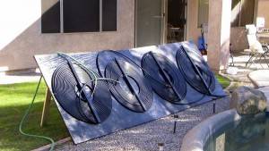 The materials from which the manifold can be made are very diverse. Known technologies for the independent production of solar collectors from polypropylene, ordinary garden hoses, window frames, plastic bottles, old refrigeration units and other materials at hand. The collector assembly scheme directly depends on the type of material selected, so it is worth studying it after the owner has decided on the concept of the collector.
Self-made vacuum solar collectors for home heating, the price of which in the store is $ 200 or more, can be used as full-fledged heating sources.
Vacuum solar collectors have a number of advantages: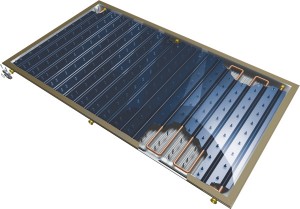
- energy efficiency;
- environmental friendliness;
- autonomy;
- availability.
 It is not difficult to make traditional distribution or solar collectors for home heating with your own hands. This does not require large material costs, sophisticated technological equipment and solid experience. Nevertheless, these self-made devices greatly optimize the heating system of the house and help the owner create a reliable, efficient and uniform source of heating for his home.
- How to pour water into an open and closed heating system?
- Popular floor-standing gas boiler of Russian production
- How to properly bleed air from a heating radiator?
- Expansion tank for closed-type heating: device and principle of operation
- Gas double-circuit wall-mounted boiler Navien: error codes in case of malfunction
Recommended reading
Heating thermostat - the principle of operation of different types How to make an expansion tank for heating with your own hands? Bypass in the heating system - what is it and why is it needed? Expansion tank for closed-type heating: device and principle of operation
2016–2017 - Leading portal for heating. All rights reserved and protected by law
Copying of site materials is prohibited. Any copyright infringement entails legal liability. Contacts
How to make a collector yourself?
An interesting overview of a homemade distribution manifold is presented in the video:
The manufacture of this useful device should begin with a project. In this case, it is necessary to take into account the following data:
- the number of heating circuits in the house;
- the number and characteristics of heating equipment that will be installed at the moment (boilers, boilers, etc.);
- the number and characteristics of heating equipment that is planned to be included in the system in the future (heat pumps, solar panels, etc.);
- the number and characteristics of additional equipment.
Additional equipment means:
- storage tanks;
- drain / fill taps;
- make-up valves;
- thermometers and manometers;
- security groups, etc.
After all these points have been taken into account, it is necessary to determine the connection dimensions for each group of pipes (supply + return), as well as for other elements of the system. Next, you need to figure out the direction of each contour. Pipes can enter the manifold from the top, bottom or side.
Solid fuel boilers and indirect heating boilers are usually cut into the ends of the collector. Gas and electric boilers are more often mounted on a distribution manifold from above, however, if it is necessary to connect through a hydraulic arrow or with its own circulation pump, it is more convenient to insert such equipment from the end. Heating circuits are most often cut from the top or bottom.
Now you can start drafting the manifold on paper. A checkered notebook sheet and a simple pencil are quite suitable for this (lovers of high-precision projects can use a graph paper sheet). The distance between the contours can be arbitrary, the recommended spread is 100-200 mm (less or more will be simply inconvenient). The distance between the supply and return of each circuit and the heating boiler can vary within the same limits. The device will look neater if this distance is the same for each contour, which will visually distinguish them.
If you plan to connect mixing modules or a pumping station of industrial production, the distance between the supply and return in the project must correspond to the characteristics of a particular model.
It is necessary to draw two long rectangles on paper (these are the supply and return sections of the collector), then the supply and return are indicated on them. Now it is necessary to use the ends of the device, for example, by marking the connection of the floor boiler.Then, the diagram sequentially indicates the connection of each heating circuit and all elements of additional equipment.
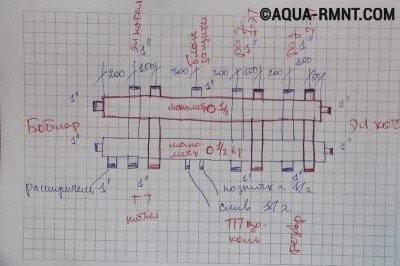
The diagram clearly demonstrates the project of a homemade distribution manifold for the heating system of a private house. It is necessary to designate the names of all contours and indicate the diameters of the threads
In the process of drawing up the project, it is recommended to immediately indicate the dimensions of all threads, as well as sign each contour and element in order to avoid possible confusion.
After the rough drawing is drawn up, checked and carefully thought out, it makes sense to take another sheet and redraw the diagram for free. Now it becomes obvious the number of materials and devices that are needed to manufacture the collector, as well as the characteristics of these devices. You can make an estimate, purchase everything you need and prepare a tool.
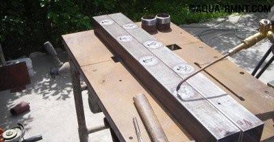
When making a distribution manifold, you need to clean the metal from rust, apply precise markings according to the diagram and cut out all the necessary holes
A homemade collector will be most conveniently made from a square metal pipe. This requires:
- Cut two pieces of metal pipe to a suitable size.
- Cut pieces of round metal pipe.
- Clean the metal parts of the future collector from rust.
- Make the markup in accordance with the diagram drawn up earlier.
- Cut out all required holes.
- Assemble the collector according to the scheme and grab the joints by welding.
- Weld all pipes and threads.
- Weld the required fasteners.
- Sand all welds by removing scale.
- Degrease the surface of the device and paint it.
It is recommended to wait a few days for the paint to dry before starting installation. It remains to connect the finished collector to the heating system.

After the distribution manifold is assembled, it is necessary to weld all the joints, weld the threads and fasteners. At the end of the welding work, the seams are cleaned
Collector circuit for heating a one-story house with forced circulation
Another type of wiring is collector. This is the most complex system, involving the use of a large number of different pipes and special distribution devices, which are called manifolds. The principle of operation of a system with a collector heating circuit of a one-story house with forced circulation is that boiling water from the boiler goes to special collectors that serve as distributors between various radiators. Each battery is connected to it with two pipes. Such a system, with its efficiency, cannot boast of being cheap. It can regulate the temperature not only on each circuit, but also on each battery, which allows you to create your own temperature regime in any room.
For the development and installation of a collector heating system, it is better to invite specialists
They make such a heating scheme for a one-story house with forced circulation, since in a natural way water cannot efficiently circulate through numerous pipes and collectors. The essence of this scheme is that a centrifugal circulation pump is cut into the return pipe directly near the boiler, which continuously pumps water using an impeller. Thanks to this, the pressure in the system is necessary in order to completely pump the entire line, heating all the batteries evenly. If you purchased a wall-mounted, expensive automatic boiler, then most likely a circulation pump is already installed in it, which is set to the optimal pressure for this boiler.If your boiler is simple, then when buying a centrifugal pump, you need to consult about its compatibility with the created pressure with this boiler in order to avoid an emergency.
Collector heating system compiled by a specialist
The collector circuit is rarely used in two-story houses, since it, although effective, is very cumbersome. The layout for two floors would be too complicated. That is why it is in demand only in the heating scheme of a one-story house with forced circulation.
Useful advice! To install a collector system of water heating in your country private house, you need to take care of purchasing the required number of thermostats and shut-off valves. This will allow you to adjust the climate in the house in a semi-automatic mode.
Circulation pump for forced recirculation of water in the heating system
Summarizing the above, it can be noted that the choice of the three existing types of water heating wiring should be carried out deliberately. In a small one-story house, only one pipe can be laid. This scheme is also called "Leningrad". If the area of the house is significant or it is two-story, then it is better to make a two-pipe heating system with a return pipe. To create a modern and efficient heating system in the house, you can mount it according to the collector circuit. It will cost more, but its efficiency will be much higher. The main thing is that any created system always works well and reliably in any, even difficult, conditions. To do this, you need to build it according to all the rules and recommendations.
Why do you need a distributor
The heating manifold is a simple device consisting of a pipe section with several nozzles, to which all heating circuits are supplied. Using a distribution manifold, several consumers can be simultaneously connected to the heat carrier:
- heating radiators in all rooms
- warm floor
- hot water boiler
- convectors and other devices
The main task of the heating distributor lies in the name itself - it evenly transfers heat from the heating boiler to all heating elements. At the same time, the device maintains the same temperature in all rooms.
All distribution manifolds are equipped with shut-off valves. It is installed either on the device itself or on a pipe that connects to the outlet pipe.
In the event of an emergency (pipe breakthrough or water leakage at the joints), ball valves installed on the boiler manifold close the damaged circuit, without shutting off the entire heating system and keeping the heat in the house. In addition, with the help of such a crane, the temperature in individual rooms is regulated.
In private houses with more than one floor, collectors are installed on each floor, which allows you to turn off the heating in temporarily unused rooms, thereby saving fuel.
The distributor for heating consists of 2 parallel manifolds. One of them is installed at the outlet of the heating agent from the heating boiler, and the return circuit of the system is supplied to the second.
Pluses of a collector heating system
The main advantages that a comb gives for heating are ease of operation and control of the system.

Additional benefits are as follows:
- By installing a collector, each component of the heating circuit can be controlled centrally and independently. You can set different temperatures in any room, turn off individual heating devices or entire groups.
- Each line laid from the collector supplies the coolant to one battery or a group of devices, so you can make a wiring from pipes of a small cross-section. The pipelines are often laid in the floor screed, trying to minimize the distance between the heater and the comb.
- If necessary, the collector circuit allows you to combine several circuits with different parameters of the coolant. In this case, a hydraulic arrow is installed, which is a type of collector and is a large cross-section pipe. It provides a connection between supply and return, regulates the flow of the coolant.
Among the disadvantages are the following:
- greater consumption of thermal energy than with a series connection;
- when using ray wiring, there is an overconsumption of materials, and the network itself will spoil the interior;
- hidden laying of pipelines has many disadvantages;
- high hydraulic resistance when using small-section pipes forces the installation of circulation pumps;
- when creating several circuits, it is necessary to install the same number of circulation pumps, which increases the cost of organizing the system;
- due to the mandatory use of pumping equipment, the heating system is volatile, therefore it is not suitable for settlements with power outages.
Collector working principle

The distribution manifold of the heating system is designed to redirect the coolant flows coming from the main line along separate circuits. The same device returns the cooled liquid to the boiler.
When using a collector for a heating system, the separately connected circuits work independently, have different parameters. In fact, it is a distribution hub, which is an intermediate link.
Its main elements:
- The return distributor directs the cooled heat carrier to the heating equipment.
- The feed comb distributes the heat carrier along the contours.
Both devices form a collector group. Each element has several outlets for connecting detached circuits. They, in turn, go to heating units. A control valve or shut-off valves are installed on each branch. Thanks to them, it is possible to regulate the pressure in the circuit and, if necessary, turn off the hotel branches in order to carry out repairs.
For the convenience of controlling the heating system, additional equipment is installed on the comb body:
- heat meters;
- flow meters;
- drain valves;
- air vent.
The collector system works according to the following principle:
- The coolant heated in the boiler enters the manifold distributor.
- Due to the large cross-section of the device, the flow rate of the coolant decreases, due to which the flow is distributed over all branches.
- Through the pipes with a smaller diameter, the liquid from the manifold assembly goes into separate circuits to radiators or warm floors. Therefore, each device receives a heating medium with the same temperature.
- Upon reaching the heater, the water gives off thermal energy and goes through another pipe in the opposite direction to the comb.
- When it enters the return distributor, the flow continues to the heating equipment.
Homemade constructions
The collector has a significant drawback - high cost.
Therefore, many "homemade products" assemble with their own hands various options for collectors, in accordance with their wallet and the availability of components.
There are two options for this path:
A 3-loop collector circuit can be implemented as follows:
First, collect the collector pipes - the return and the coolant that feeds the heating circuits. To do this, use one comb for 3 channels or 3 single-loop nodes for each collector. The return collector is equipped with a flow sensor or a flow meter and a counter-mounted connection node for the return supply hoses for each loop.

One-loop collectors are connected by threaded elements into a comb. Each coolant loop contains a heat sensor with an actuator and a unit for connecting the heating circuit power supply line. Air vents are connected to one end of the collectors, and on the other, a coolant pump is connected to the collector pipes, and in addition to this point a thermostatic valve or servo drive is connected, which from time to time replenishes the mixer with hot water. The assembled manifold is attached to the wall, tested for functionality and connected to the heating circuits. After that, the final installation and adjustment of the entire system is carried out.
Here is the simplest working version of a collector for a warm floor available to a wide range of homemade craftsmen. The capabilities of real collectors are often expanded by connecting more complex regulation and metering systems.
For example, they connect heat meters, additional temperature meters and much more, who are in a lot - that is why there are self-made inventors in order to "assemble something yourself".
If a homemade collector is soldered from polypropylene pipes, then you need to replenish your arsenal of tools with a special soldering iron for welding parts from this polymer.
When assembling by welding, the size of each single-loop assembly increases due to seams, and if there are more than 3 thermal circuits, then the entire collector becomes cumbersome, and its installation becomes problematic. Otherwise, the scheme of the plastic collector and its setting are no different from those described earlier.
Well, now it's time to finish the article. All the material that I wanted to share is reviewed. I hope it will be useful to you, and you will use it if you need to install a collector for underfloor heating with your own hands Improve your own practical skills and gain all the new knowledge, as they say: "It's never too late to learn!" That's all, thanks for your attention, successful and easy repair!
Why do you need a distributor at all?
In a house where several heating circuits are installed, a distribution manifold is a must. If we sum up the diameter of the inlet of each circuit and compare it with the diameter of the boiler connection pipe, it will become obvious that the latter figure is much less. For example, the branch pipe of a wall-mounted gas boiler is most often ¾ "in diameter. Let's say they connect to it:
- radiator system;
- underfloor heating system;
- indirect heating boiler.
The connection diameter of each consumer is 1 inch. Will the coolant have time to flow through the ¾ "outlet to three 1" inlets? The answer is obvious: during the operation of such a system, it is quite natural that a shortage of coolant arises when all heating circuits are turned on simultaneously.
For example, the radiator system works fine, but when the additional underfloor heating system is turned on, a decrease in temperature is observed, the air in the rooms does not warm up. Simply put, hot water does not enter the system quickly enough.

The distribution manifold allows you to fully control the operation of the heating system of a private house and customize it to the specific needs and desires of the owner
To solve the problem, you will need to install a distribution manifold. This is a special metal comb on which a number of I / O devices are installed for each individual heating circuit. The collector allows you to regulate the volume of the coolant entering the system, its temperature, pressure in the system, etc. With this device, you can carry out centralized control over the heating process of each individual room equipped with its own heating circuit.
Connect through the distribution manifold:
- underfloor heating systems;
- radiator systems;
- converters;
- panel heating systems, etc.
The distribution manifold has a supply and return section, which are connected to each other. The supply manifold allows you to control the actual supply of hot heat carrier to each specific heating circuit. This is very convenient, because in the event of a breakdown, you do not need to turn off the entire system, you can only shut off a separate circuit and make the necessary repairs. The return section of the collector is necessary to regulate the pressure in a specific section of the system so that the heating quality reaches a predetermined level.
You should not try to remedy the situation by installing additional circulation pumps or special valves. They will not help fill the heating system with a sufficient amount of coolant. But the distribution manifold copes with this task quite successfully.
Please note that in a large house with two or more floors, it is recommended to use a separate distribution manifold for each floor.
