The difference between an independent oven and a built-in
Most of the apartments are equipped with an oven and hob suitable for cooking food. Furnaces are conventionally divided into independent and built-in ones. They have differences in mechanisms and installation. These are important points when choosing equipment.
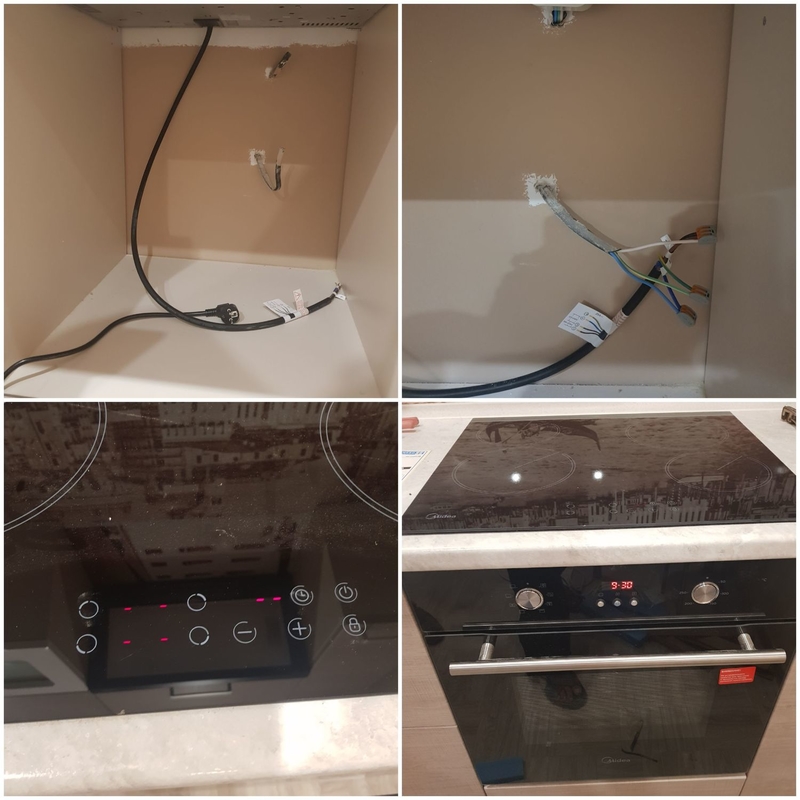
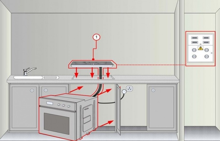
Built-in electric ovens are usually built into the designated space. The electric stove is located only above the oven itself, since they have one power supply and regulation system. Together they create a complex. The stove has no buttons, and its modes cannot be adjusted. The cooking zones will not be able to function without the control unit on the oven. To connect the oven, electrical feeders are used, powered by central power grids. There is a large selection of different models of built-in ovens on the market. Having decided on the equipment and functionality, you can easily find a good device.
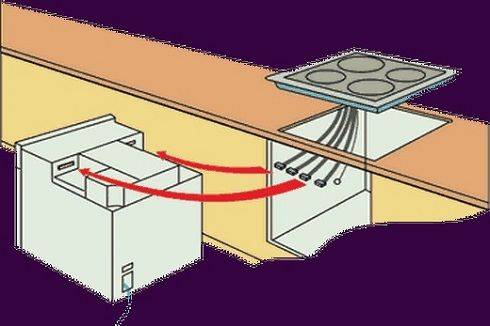

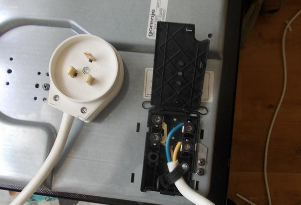
Over time, built-in surfaces have been replaced by independent household ovens that are easy to use and easy to place. Independent models allow you to place the oven anywhere in the kitchen, regardless of the placement of the hob. They differ in that they have their own adjustment levers. The adjustment can be carried out by means of manual toggle switches, buttons and a sensor. They are independent of each other, which makes their installation easier. The plug for the hob is separate, respectively, they are connected to electricity separately.

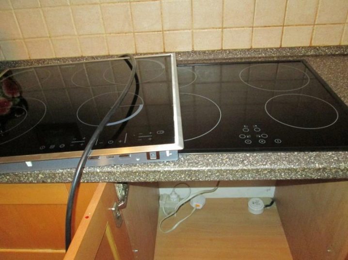
An electric oven and an electric stove can be installed in different places of the kitchen set, and not under each other, as in the built-in version. Each device can be selected by the manufacturer, which is preferable, choosing the functionality. Someone does not need a hob at all if food is regularly cooked using auxiliary household appliances, and the main cooking lies on the oven. In this case, you can buy a surface with a pair of burners, which will save finances. Installation can easily be done by hand.
Compliance with safety measures when connecting the hob to the gasification and electrification system
The safety precautions mainly depend on the type and model of the hob. However, there is a high temperature hazard for any gas surface:
Electrical safety measures depend on the correspondence of the indicators of the power consumption of the stove and the capabilities of the electrical network. The network must have a "neutral" wire, and the socket at the stove must be equipped with a circuit breaker with an earthing contact.
The power system protects the power grid from overloads. Due to the presence of a residual current device (RCD), there is a high protection of a person from the negative effects of current.
To prevent damage to individual units of the gas panel, a number of protections are provided, for example, temperature limit sensors, a power cut-off system for heating the oven above the permitted value. In accordance with fire safety standards, the temperature indicator on the outer panels of the slab should not be higher than 90 degrees.
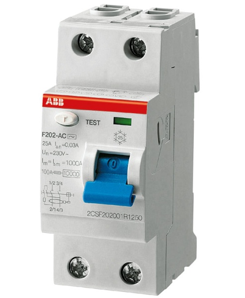
Residual current device for gas cooktops with electric ignition
Safety in the use of household appliances is ensured by the "gas control" system. If the flame goes out and the temperature drops below the control value, then the system will automatically cut off the gas supply to the burners.
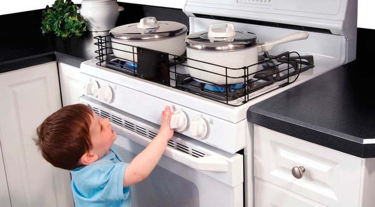
The hob connection diagram provides for the locking of the control knobs, which are held by magnetic attraction on the metal surface. They can be easily removed.Removable control sticks not only eliminate dangerous pranks of children with them, but also prevent accidents.
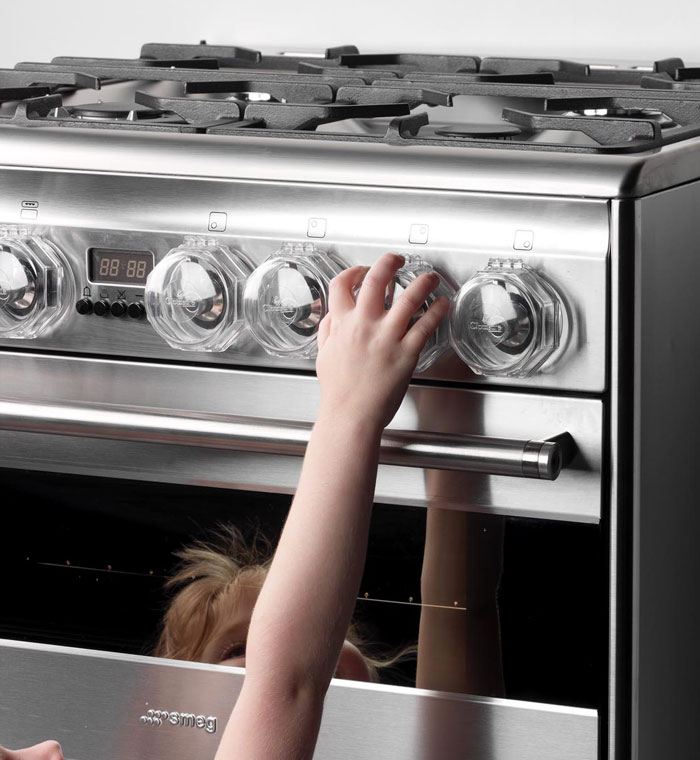
Child protection mechanism
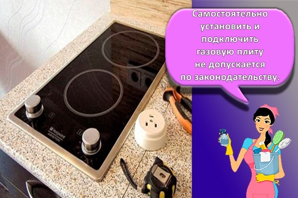
Installation and connection of the built-in gas hob can be carried out independently, having basic knowledge in the field of gas distribution and power supply. However, it is strongly recommended to contact a specialized organization licensed to perform this type of work.
Often people are faced with such a question as installing a gas hob with their own hands. A kitchen set, as well as an oven and a gas stove, are not a cheap pleasure these days. People who spend large sums on furniture renovation want to save the family budget by installing a gas hob. To carry out this work, you yourself need to take accurate measurements and find out a few nuances for installing equipment.
Connecting an induction hob in a flap
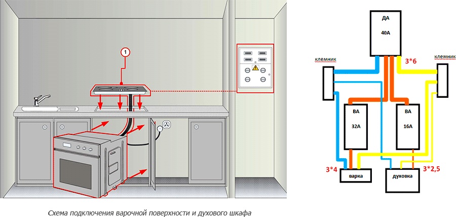
Installation of the hob is impossible without connecting it through an RCD + an automatic device, or a differential circuit breaker with a leakage current of 30mA. Such additional equipment makes the operation of the panel as safe as possible, increases protection against electrical injuries and against spontaneous combustion if there is a current leakage due to damaged insulation. The algorithm for connecting the induction panel in the shield is not complicated.
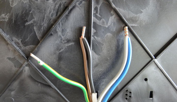
- The phase wire (gray or brown) in the shield is connected to the lower terminal of the differential machine. It is usually denoted by the number 2.
- The neutral wire (blue) is connected to the terminal marked with the Latin letter N.
- The ground wire (yellow-green) is thrown to the ground bus.
After the connection in the dashboard has been made, the hob can be connected to the mains.
Connecting a gas hob: a set of necessary tools
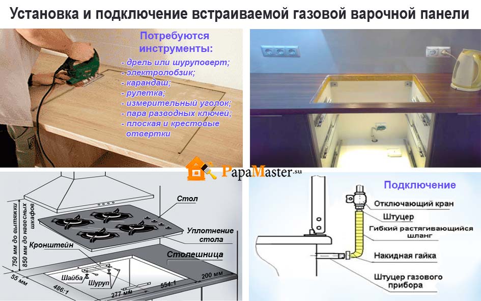
To mount this equipment, you will need the following set of tools:
- graphite pencil;
- silicone sealant;
- adjustable wrench number 2;
- linen thread;
- multimeter;
- corrugated hose subject to mandatory certification;
- jigsaw.
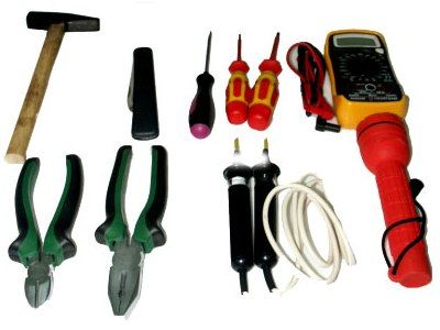
Necessary locksmith tools
The panel should be located in a well-ventilated and ventilated area, with a Ross point of not more than 70%. To achieve certain parameters, a supply and exhaust air removal system is created, where the amount of required air must be 2 m 3 / h.
Before the installation is carried out, the following order of technical measures is performed:
- A technological hole in the kitchen set is selected for connection to gas;
- If the panel has an auto-ignition device, it is necessary to supply power to the device module 220 V, for this you will need:
- jigsaw;
- saw with a step of 1.5–2.0 mm;
- PVSnG wire with a cross section of 2.5–4.0 mm 2;
- conductors according to the electrical safety class with the degree of protection P1 and double insulation.

PVA wire with a cross section of 3x2.5
- Apply the template to the surface to be cut out, adhering to the width, height and depth of the hob.
- To properly cut the hole for the panel, place the template on the worktop and draw its base. Next, carefully cut the hole with a jigsaw. The next step is to treat the seat with a sealant. It will protect the material from moisture.
- Next, lay out double-sided tape on the surface to be cut and make a ruler.
- Using a jigsaw, cut the mounting hole to fit the panel. If a standard hole is provided, then no additional measures are required.
- If such measures are necessary, then you need to degrease the cut hole with soapy water or a special suspension.
- Gas panels are installed on a horizontally flat surface that does not have deviations of more than 2 degrees.
The panel is lowered into the selected hole on the table top, while, if necessary, the edges are evenly spaced along the gasket around the entire perimeter of the gas equipment.

Connection diagram
Even the slightest thermal gap can cause water and other liquids to spill onto the oven. This problem can be the cause of a power outage. The presence of moisture under the panel can provoke the appearance of pathogenic microorganisms and surface delamination.
It is required to install the surface clamps on the adjusting springs so that most of the bracket is under the countertop area. Hold the springs in place, use the other hand to tighten the bolts with a screwdriver in the direction of the arrow until you hear a click.
To ensure a tight connection to the gas distribution system, flax is applied to the surface of all threaded connections, both on the hob and on the gas pipe. In the area of the gas hose, gaskets are inserted, if such are provided by the operating instructions and do not contradict safety measures.
Screw the threaded hose connections to the hob and gas pipe, turn clockwise until the nut stops, then tighten with a wrench. It is not necessary to exert great effort, this can lead to pushing through the paronite or fluoroplastic gasket and to gas leakage.
Paronite gasket and IFS
The gas panel device has a nominal passage diameter G1 / 2, which is necessary to connect the device to the gas system. For liquefied gas (propane, butane, isobutane), a 9 x 1 mm 2 ferrule is screwed onto the end of the hose. The flexible gas line carrying gas must not touch the metal components of the coating.
Types of electric stoves
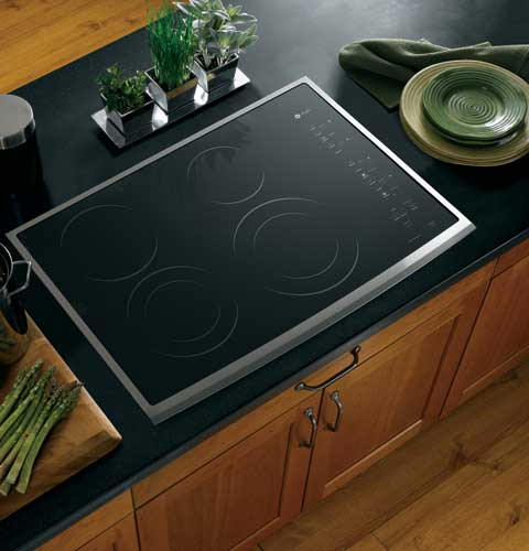
Modern household electric stoves are divided into two categories, each of which is characterized by the type of hob:
- products with an enamel top and cast iron burners;
- models with glass-ceramic hob.
The disadvantages of any models, outside of their category, should include some thermal inertia - their hobs slowly reach the operating temperature and also slowly cool down. Therefore, it can be quite difficult to establish the required temperature regime. Because of this, the budget options provide for a fixed adjustment of the heat output - by three ... 6 positions.
The undoubted advantage of products with cast iron burners is their more affordable price. Models with glass ceramic surface have a flat hob. As heating elements of these products, tape, halogen or induction devices can be used, in which it is much easier to adjust the power.
Therefore, cheap glass-ceramic electric stoves have a simple rotary knob, and expensive models can be equipped with electronic or touch controls. In addition, the design of burners took shape decades ago and today is determined by the type and size of heating elements. The appearance of stoves with a glass-ceramic hob is constantly being improved, they have a more stylish look and greater ergonomics.
The disadvantages of glass-ceramic models include the discrepancy between the size of the hob and the bottom of the kitchenware. However, this disadvantage is compensated by the use of several individual heating elements.
Today, the most popular brands of household kitchen electric stoves are Beko and Vestel (Turkey), DeLuxe (Russia), Gefest - Gefest and Atlant (Belarus), Ardo, Candy, Indesit and Zanussi (Italy), Blomberg, AEG and Bosch (Germany), Electrolux (Sweden).
Of course, the quality of work of any product, regardless of the brand, depends on compliance with the operating rules. At the same time, the correct connection affects not only the operational characteristics, but also the safety of use.
You should know that electric stoves are available with a supply voltage of both 220.0 volts and 380.0 volts. For a city apartment, you should choose products of the first category.If a person lives in a private house and has a three-phase supply, then preference should be given to electric stoves designed for a voltage of 380.0 volts.
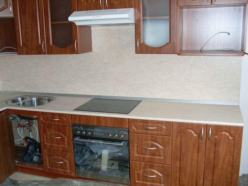
Installing the hob
The installation of an electric hob is carried out in accordance with the general requirements, regardless of the type of heating element using a high frequency induction field or heating by resistance to electric current. By their external design, these types of devices are practically indistinguishable, therefore, the same tools and consumables are used for their installation in the kitchen. If we talk about electrical panels of any kind, then all of them will be built into the furniture. Those appliances that are located on the surface of furniture are called electric stoves without an oven. We will not consider the process of how they are installed.

How to install the hob correctly? This question arises if furniture suppliers have not cut a mounting opening on the kitchen countertop. If you decide to perform this operation yourself, then you will need the following tools: an electric jigsaw, a drill, wood drills, a ruler and a pencil, as well as a screwdriver and pliers. The step-by-step algorithm for the installation of the built-in hob is presented below.
- Sizing. At the first stage, we determine the dimensions of the opening into which the device must be built. This information is reflected in the instruction manual for the equipment. If it is absent, then it is necessary to make a careful measurement of the device seat. 5 mm must be added to the overall dimensions to ensure optimal clearance.
- Opening markings. To perform this operation, you will need a long ruler, square and pencil. The installation opening should be at least 50 mm from the edges of the table. Otherwise, thinner sections of the countertop may collapse, especially if it is made of low-quality chipboard. This concludes the preliminary work.
- Drilling holes. At the corners of the resulting rectangle, it is necessary to drill four through technological holes, without going beyond the marked contour. The operation should be performed with a wood drill with a diameter of 8–10 mm. Drilling must be strictly perpendicular to the surface of the tabletop, holding the drill securely in an upright position.
- Cut out the opening. We insert the blade of an electric jigsaw with fine teeth into one of the holes and cut the tabletop along the markings, pressing the tool tightly to the table surface. In a similar way, we cut the tabletop along the entire marked contour. After completing the work, we check that the dimensions of the mounting niche correspond to the seat of the electric hob.
- End machining. The ends of the mounting hole must be protected from water. To do this, you can use a special sealant or any other material that can protect the wood base of the countertop from the negative effects of moisture. The gasket supplied with the hob is glued to the edges of the installation opening.
- The final stage. At the final stage of installing the hob, carefully place the device in the mounting opening. Before this operation, you can apply a layer of silicone sealant to the area of the countertop that will be covered by the edges of the panel. The appliance should fit snugly against the surface of the worktop with a minimum gap. We fix the panel on the tabletop using standard fixing clamps.
This completes the installation of an induction hob or other type of surface. You just need to check the reliability of the fixture of the device to the table top and you can proceed to the next step. We told how to install the hob, now we will describe the process of connecting it to the electricity supply network.These chapters of the article can be considered as a guide for those who are going to independently connect the electric hob to the power supply. So, let's begin! The next section of our story will be devoted to the hob connection diagram.
Connecting the electric stove according to various schemes
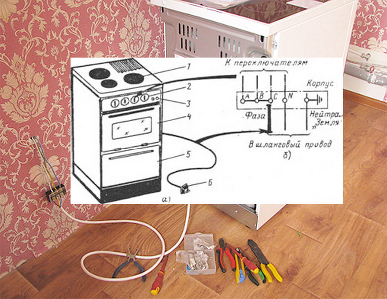
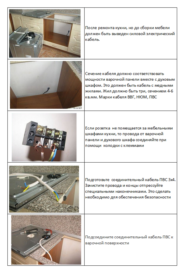
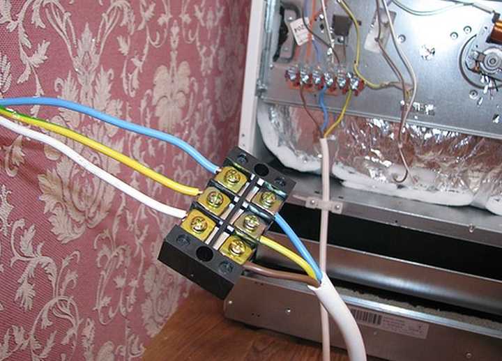
Most modern manufacturers of electric stoves supply their products to the retail network without being equipped with a power cord. This is due to modern electrical safety requirements, which imply the connection of high-power devices using a socketless method - using special terminal blocks.
This method has two main advantages:
- the power cord can be chosen of any length;
- it is possible to replace an individual machine with a fuse (insert).
If the length of the cord does not exceed 6.0 meters, then the electrical section of each core can be taken equal to 4.0 square millimeters. With a greater length, the minimum cross-sectional value increases to 6.0 square millimeters and the installation of a fuse-link is prohibited, and power is supplied only through a circuit breaker.
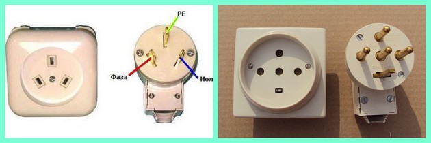
In principle, an electrical appliance can also be connected using a special plug-socket pair. However, these fittings must be rated for at least 32.0 amperes, and the use of regular household plugs is prohibited.
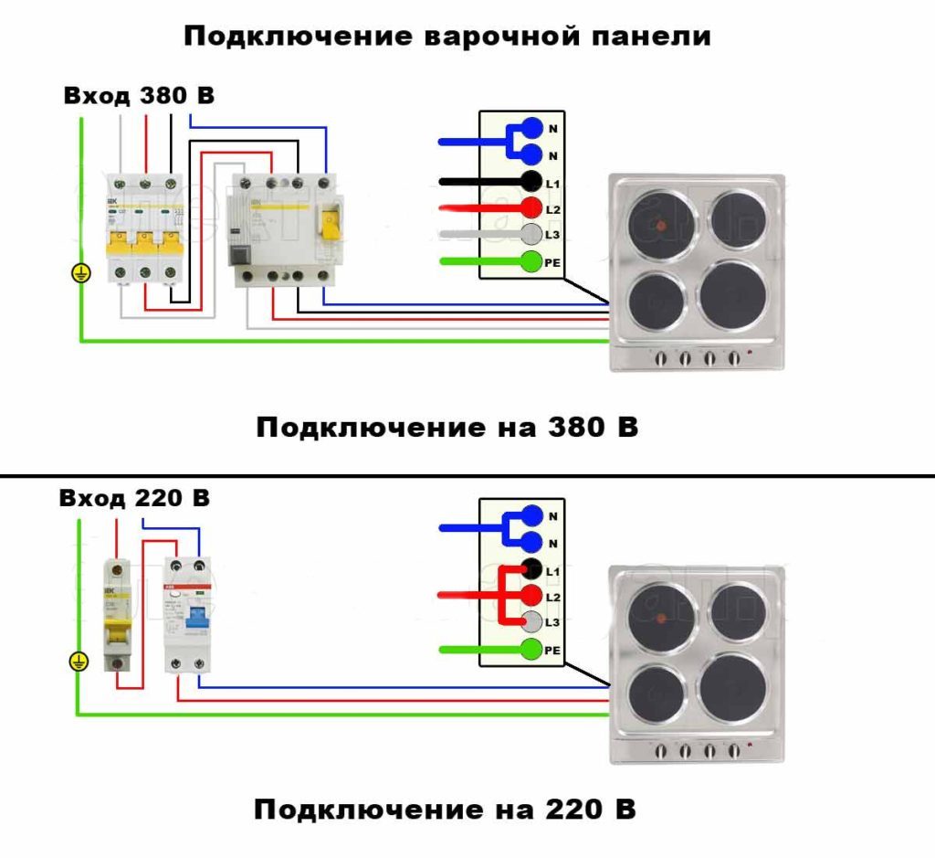
Single phase connection
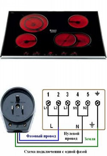
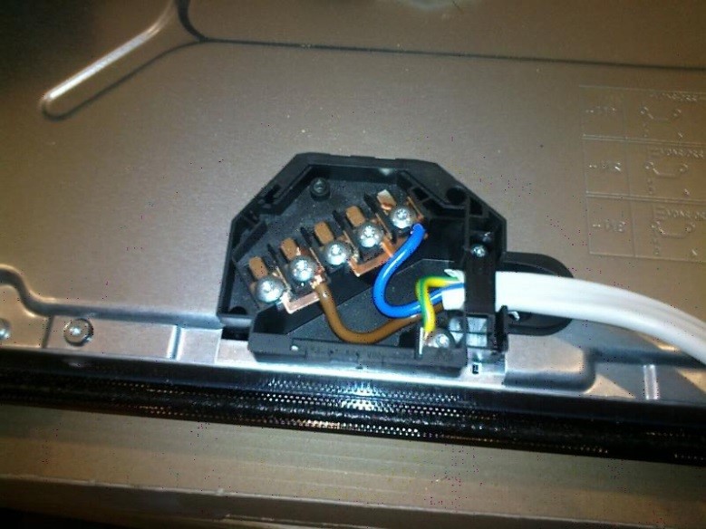
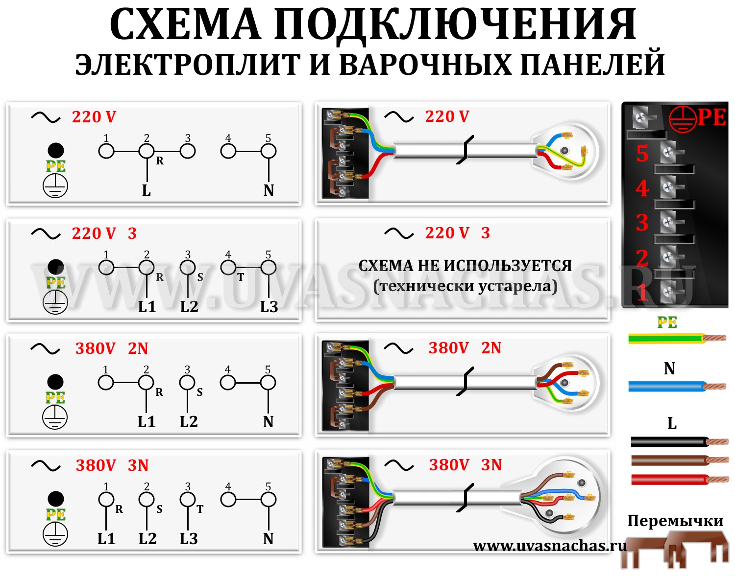
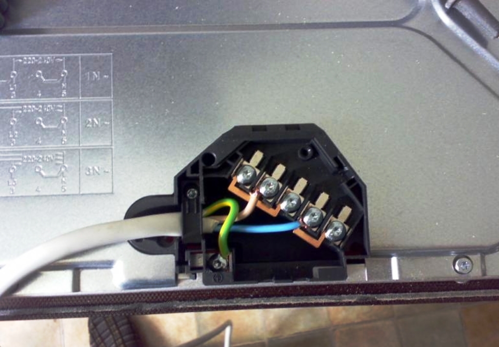
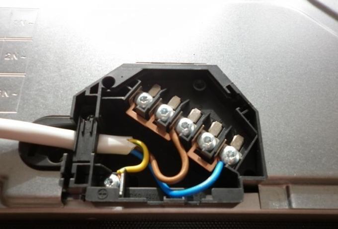
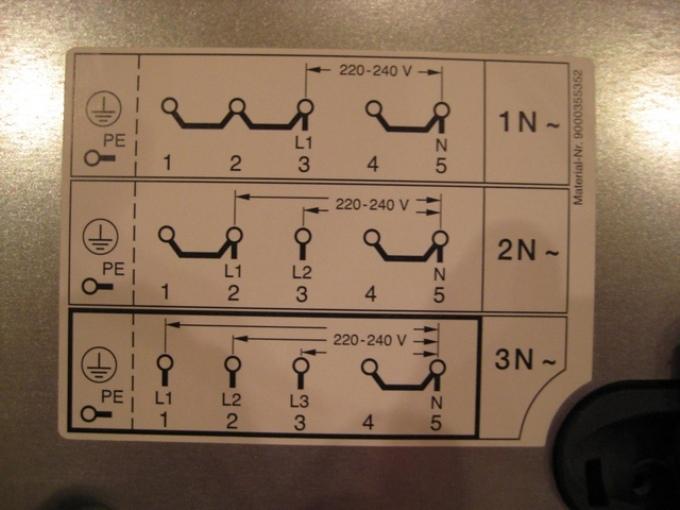
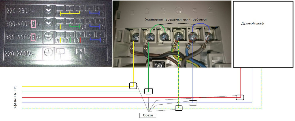
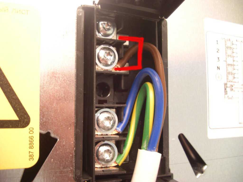
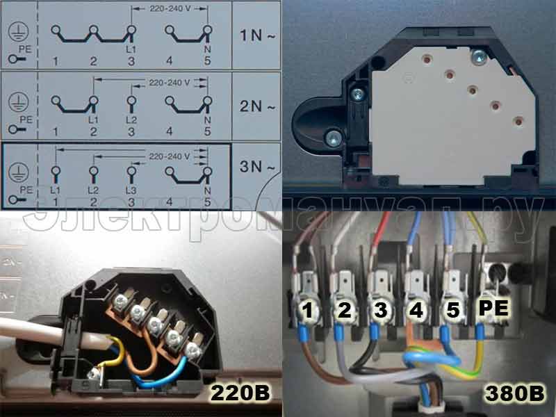
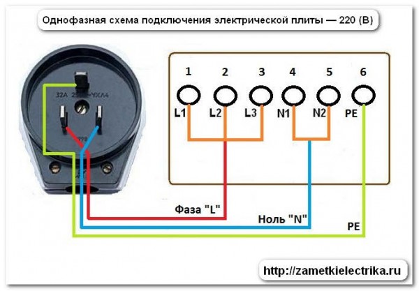
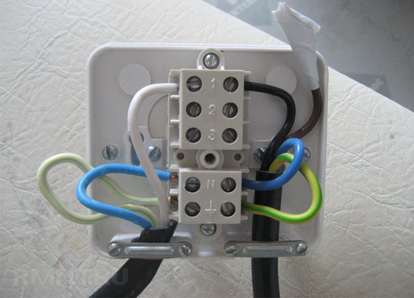
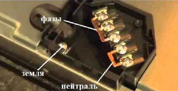
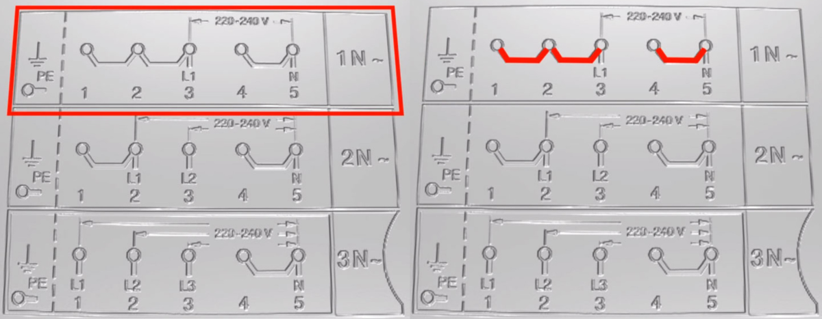
Single-phase connection (Fig. 1) is most common in urban apartments in multi-storey buildings. To implement it, it is necessary to set appropriately the jumpers in the terminal box (located on the rear panel) of the electric stove. All modern models are equipped with jumpers of the required section. If there are no jumpers, then they must be purchased at an electrical store or cut out of the copper core yourself. The minimum electrical cross-section of the jumper is 6.0 square millimeters.
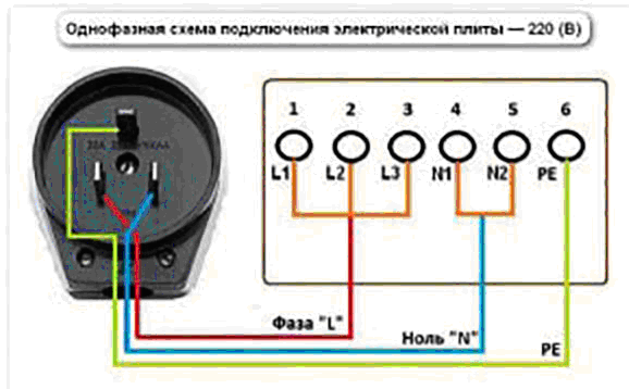
Fig. 1
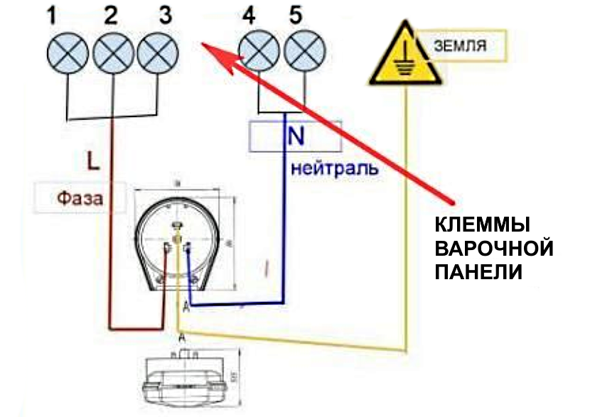
According to the diagram, for a single-phase connection, you must:
- connect terminals 1-2-3 with jumpers and connect to the phase wire (brown, gray or black) of the supply cable;
- connect terminals 4-5 to each other and connect to the zero core (usually colored blue);
- connect terminal 6 to the grounding conductor of the cable - for a single-phase network with a voltage of 220.0 volts, this wire usually has a smaller cross-section and is colored yellow or green.
When making all connections (wires to terminals and jumpers between terminals), reliable electrical contact must be ensured, for which the nuts in the terminal box must be tightened well. With a poor-quality contact, the connection will warm up, spark, which will lead to a minimum of burnout of the insulation of the terminal box, and a maximum of a fire.
Connect the power cable to the plug as follows:
- the phase wire is connected to the plug (terminal) "L";
- zero - to plug "N";
- earthing - to the plug marked with a conventional grounding symbol (in some products, the grounding contact is marked "earth" or "PE").
Two-phase connection
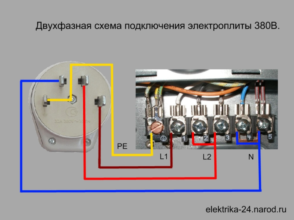
Two-phase connection (Fig. 2) is used quite rarely and can only be performed in residential premises if there is a three-phase network in them. In this case, the electric burners will be connected to two phase wires, and one phase will remain unloaded.
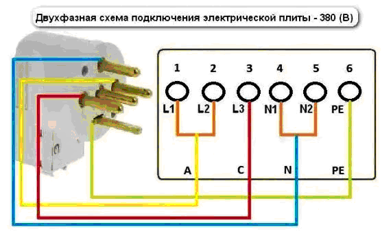
Fig. 2
The procedure for installing jumpers, connecting the cable to the plate and connecting it to the plug is as follows:
- we connect terminals 1-2 or 2-3 with a jumper and connect to the first phase wire;
- a free phase terminal (3 or 2 depends on how the jumper is installed) is connected to the second phase wire);
- the installation of jumpers (4-5) and the connection of the neutral and ground wires are carried out in the same way as in the single-phase scheme.
To connect the electric stove using a two-phase scheme, it is necessary to purchase a set "plug-socket" for powering three-phase equipment, while one plug of the plug will not be used.
Three-phase connection
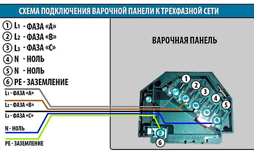
Three-phase connection (fig. 3) requires a three-phase network and is mainly used in individual houses. As you know, their course of general electrical engineering, the voltage between the phases will be 380.0 volts, and between any phase and zero - 220.0 volts. To implement it, you will need a four to five core cable.
The cables connected to the terminal box are as follows:
- no jumpers are placed between the phase terminals (1-2-32), and each terminal is connected to a phase wire;
- the installation of jumpers (4-5) and the connection of the neutral and ground wires are carried out in the same way as in the single-phase scheme.
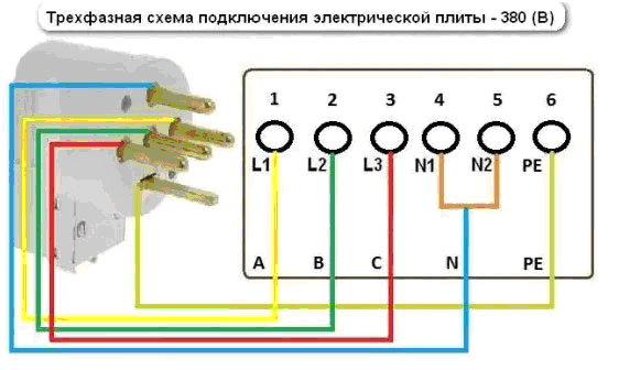
Fig. 3
When performing electrical work on your own, you should be aware that some models do not have a terminal box, and the connection is made to the contacts located on the rear panel shield.
Frequent connection errors
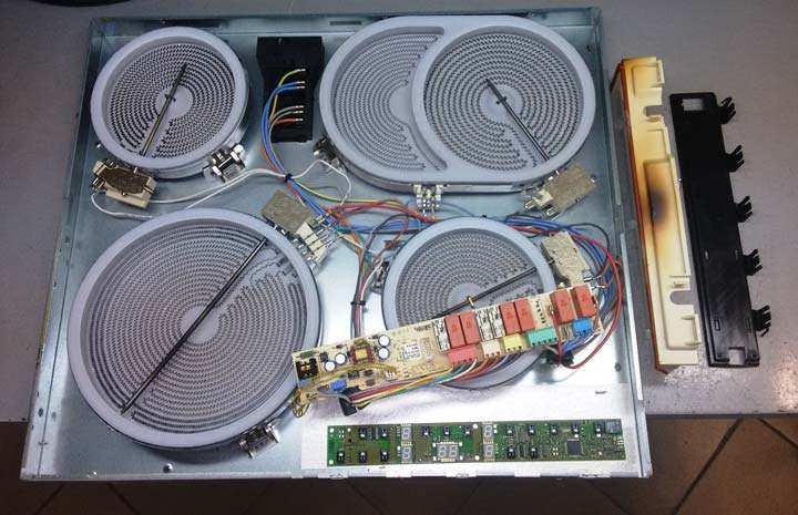
When connecting the stove on your own, various errors and miscalculations are possible. They often cause equipment malfunction or lead to fires. To exclude them, you should take into account the following requirements:
- It is strictly forbidden to use a simple plug and socket of 16 A for induction hobs with a power of 3.5 kW or more.
- If the cable cross-section is 2.5 mm, it cannot be used for plates with a power of 7 kW or more.
- If there is no phase jumper on one of the terminals, some of the burners will stop functioning, or the stove will not turn on.
Often, users complain about the strange operation of the hob, claiming that it turns on and off randomly. A similar problem does not arise due to the erroneous connection of the wires, but due to the operation of the child safety device. Such a function is present on most modern stoves and is launched when the control keys are pressed chaotically. In addition, there are devices on sale with the option of recognizing dishes - if there is no kitchen utensil on the burner, it will not start.
If during the start-up of the hob only half of the cooking zones are activated and others show residual heat, there may have been some connection errors. This phenomenon occurs when three-phase systems are connected in a single phase. The panel automatically limits the supply of current.
It is not difficult to connect an induction hob in an apartment or a private house. However, such a process requires increased attention and responsibility from each user. Before starting work, a number of factors should be taken into account, including the power of the network, the number of phases and the parameters of the wires laid between the plate and the switchboard.
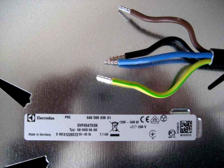
Electrolux hob connection 4 wires
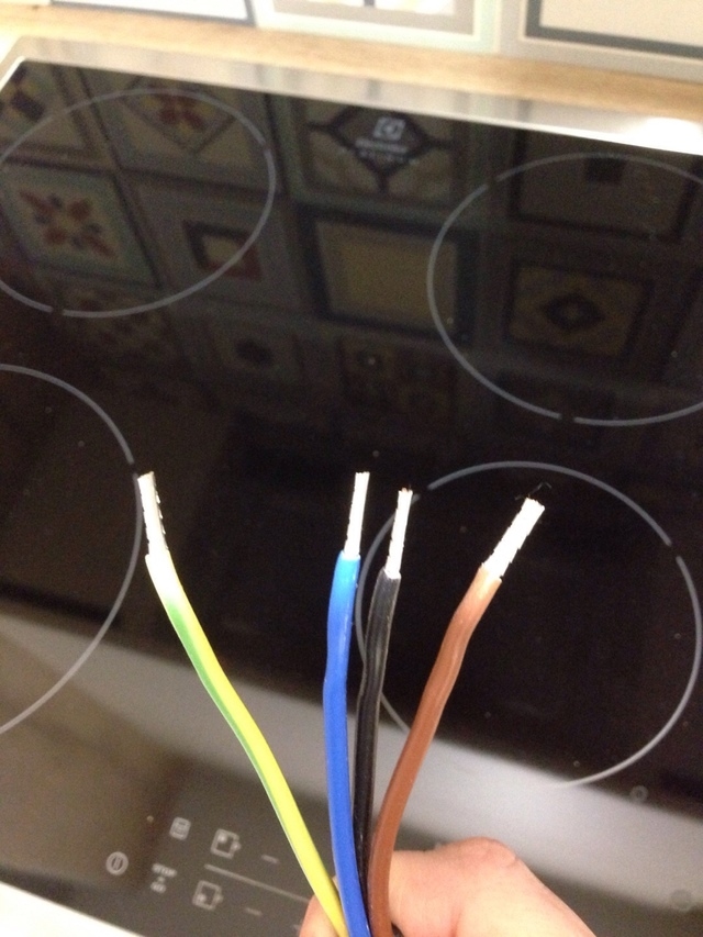
Some models of hobs from Electrolux, Bosch, Hansa, Gorenje have a four-core wire. Therefore, it can be very difficult to decide where to connect them if there are only 3 wires in the apartment.

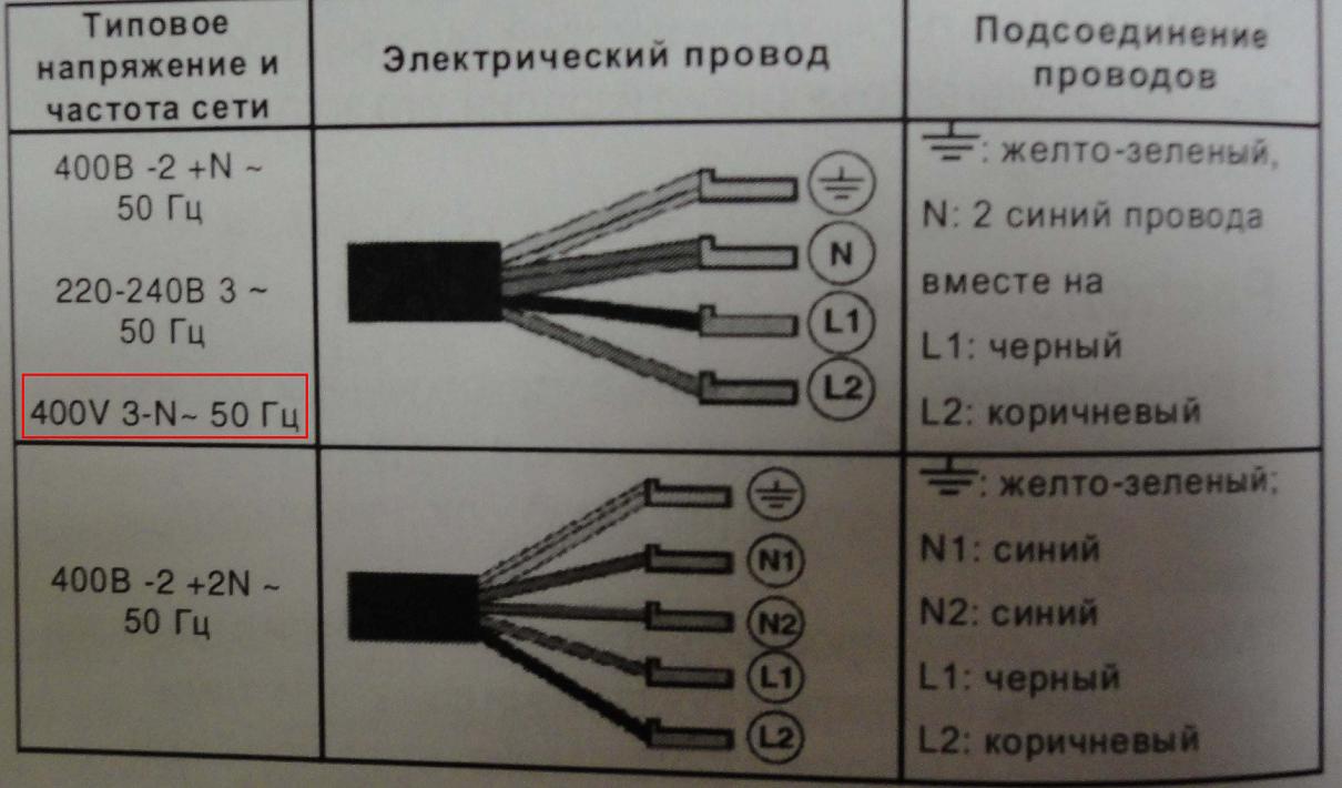
A four-core cable consists of the following wires: zero, earth and two phases. To properly connect the wire to the hob, you need to know some of the nuances.
Installing a 4-wire hob:
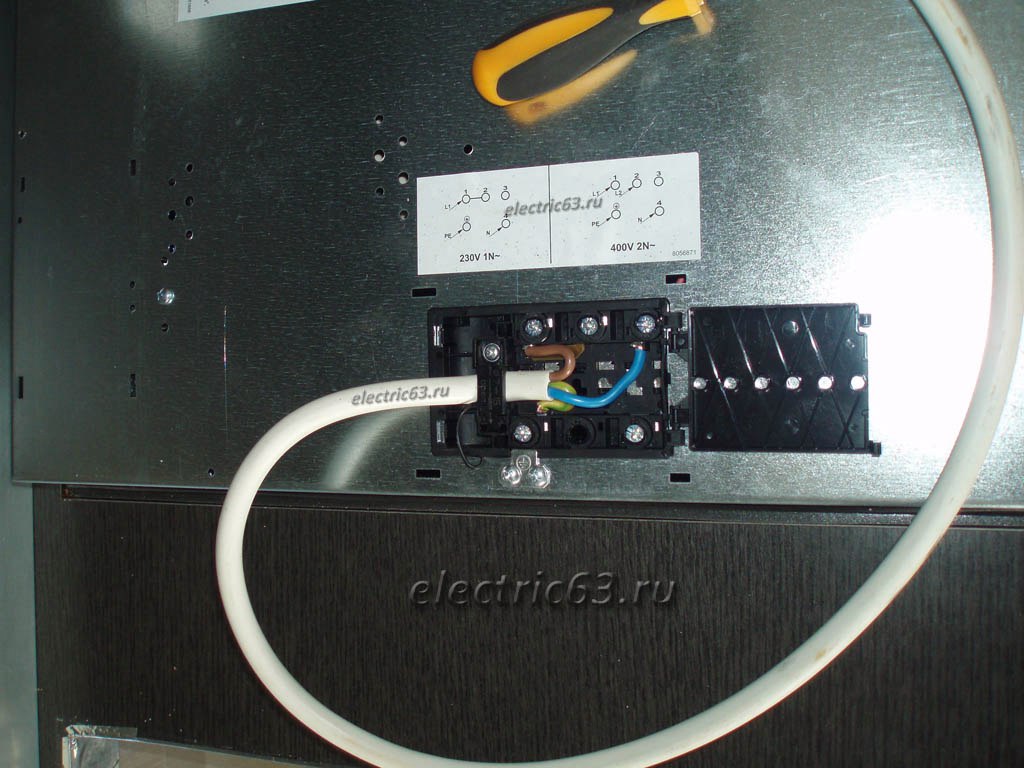
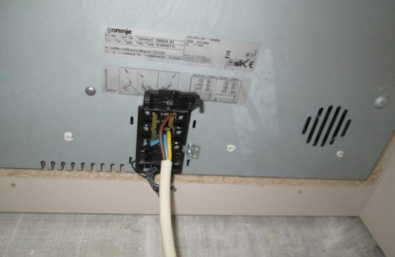
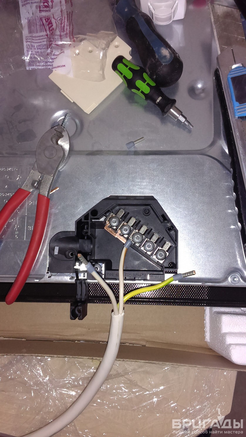
- Find the location where the terminals are located. They are usually found on the back of the case. Unlike Bosch panels, Electrolux has a plastic case. To open it, you just need to pry off the cover with a screwdriver.
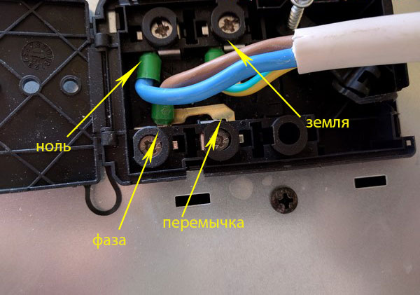
- Find the ground outlet in the open box, it is usually yellow-green in color. A two-wire jumper should be located near this output. Phase wires are inserted into it, they are black and brown. To do this, you need to check the screws with a screwdriver, slip in the jumper and tighten everything.
- When connecting the plug, you will need to use only the brown wire, and the black wire will need to be insulated with a thermotube.
All further actions when you connect two-phase equipment are performed in the same way as you would connect a single-phase electrical panel.
Electricity connection cost
Before you independently engage in connecting the electric stove, you should call the service center and ask how much these work performed by a specialist will cost. At the same time, the owner of household appliances gets rid of a lot of problems associated with both the time spent and sometimes unfamiliar work.
Typically, a repair shop conducting electrical work takes care of service and warranty repair of the product.
For example, in Moscow, when performing the entire range of works, the standard prices are as follows:
- purchase of the necessary materials and components (excluding their cost) - 350.0 rubles per hour of time spent;
- installation and connection of an electrical outlet - 450.0 ... 750.0 rubles per unit (depending on the type of connection);
- installation of electrical wiring with connection to the panel 150.0… 350.0 rubles per running meter;
- installation of an electric stove - 1000.0 rubles.
There are companies that offer to perform the whole range of turnkey works, without the intervention of the owner, for 20.0 ... 50.0 North American dollars. At the same time, the high price applies to equipment with a glass-ceramic hob.
In the provinces, prices are somewhat cheaper. In Krasnoyarsk and Novosibirsk, the cost of wiring and installation starts from 800.0 rubles. In other regional centers, in the Central regions of Russia, many firms offer their services for similar work in the range of 400.0 ... 500.0 rubles.
Electric stove connection diagrams
Before proceeding with the direct installation of the device, study the existing connection diagrams of the device.
Single phase connection
The most common option. Most often found in apartments of multi-storey buildings.
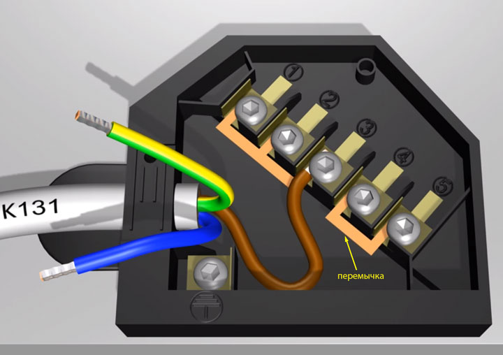
With a single-phase connection, the connection block will look like this (see diagram).
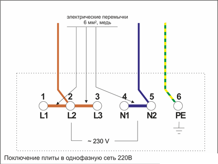
Terminals 1-2-3, as well as 4-5 are connected with copper jumpers with a cross section of 6 mm 2. If you bought a modern cooker, the necessary jumpers will be included in the kit.
The phase conductor (can be gray, brown or black) is connected to terminal number 1, 2 or 3.
The zero core (usually blue) is connected to the 4th or 5th terminal. The ground wire (in the diagram it is yellow-green) is connected to the 6th terminal.
The terminal bolts must be tightened to the stop. In the event of a poor connection, the terminals may be burned, which will lead to a fire.
In the case of using a socket connection, the phase conductor in the plug and socket is fed to terminal L, the zero conductor will go to the terminal marked N, and the ground wire is put into the corresponding terminal (marked with a grounding pattern, the letters PE, or the word earth).
Two-phase connection
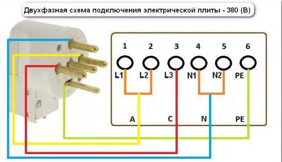
Rarely, but still there is a two-phase connection. For example, phases A and C may be present, but phase B will not.
With this connection, terminals 1 and 2 must be connected with a jumper and phase A must be connected through it. Phase C goes to the 3rd terminal. The further connection procedure remains similar to the previous methods.
Three-phase connection
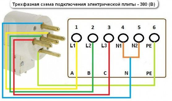
Three-phase power supply is most often encountered by owners of private houses. The supply wire in a similar situation will consist of 4 or 5 cores. In this case, the voltage between zero and phases will be 220 V, and between the phases itself - 380 V.
In such conditions, the electric stove will be connected according to the appropriate scheme. Phases A, B and C will go to the corresponding terminals 1, 2 and 3.
Terminals 4, 5 and 6 are connected in the same way as single-phase.

