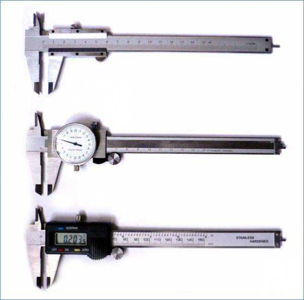
From the history of the instrument
The history of this tool is indicative to consider in the context of the history of metalworking and one of the directions of its development - turning. The historical period of the 15-18 centuries is characterized by a series of scientific discoveries and the practical implementation of these discoveries in all sectors of the economy of this period.
The use of a mathematical approach in astronomy expanded the horizons of maritime navigation, the era of the great geographical discoveries raised the volume of trade and industrial production to a new level. Small-scale production gave way to manufacturing, and the industrial revolution of the 18-19 centuries finally established the transition to the mass use of machines and industrialization.
Chronology of events
For clarity, you can imagine the chronology of these events, including the key points of the appearance of the caliper:
- The beginning of the 16th century - lathes are used mainly for processing wood, bone and soft metals. The drive, although improved from ancient times, is still hand or foot, just like the cutter, remains in the hands of the master. A milestone can be considered the appearance of a steel center and a steady rest for fixing the workpiece.
- The attempt by the Portuguese mathematician Pedro Nunez, directly related to the caliper, to create a device for accurately measuring angles using a set of concentric circles divided into equal parts, dates back to the same period. The goal was not metalworking, but the pressing problems of navigation. The matter did not come to the manufacture and practical application of the device, but the direction of thought did not go unnoticed.
- By the middle of the 16th century, lathes were equipped with a mechanical water wheel drive, which made it possible to start cutting steel. At this time, the first samples of a modern caliper appeared in the workshops - wooden rulers with movable measuring jaws and an applied scale for direct measurement. Returning to Michelangelo, we note that it was the compass that was the prototype of the caliper - the parts were measured with the legs of the compass, and the value was determined using a ruler. Obviously, there was a wizard who simplified this procedure by combining both instruments in one and reducing the measurement to one operation.
- In 1631, the Burgundian mathematician Pierre Vernier finished the work begun by Nunes, refining his idea and adapting it technically in the quadrant for measuring angular values. The additional measuring scale created by him immediately took a wide step in many directions of measurements, while receiving the names in honor of both scientists - "vernier" or "vernier". At the same time, the concept of vernier is mainly used in metalworking, vernier is more common in the instrument and radio engineering industries.
- The result of constant improvement over a period of more than a hundred years was the equipping of the lathe by the beginning of the 18th century with a support for rigid attachment of the cutter, longitudinal and transverse feed mechanisms. The turners already had at their disposal a measuring tool with a vernier scale, which made it possible to ensure the appropriate workmanship.
- By the end of the 18th century, a universal lathe was born, the principle of the device and operation of which has changed little to this day. This period is associated with the emergence of the concepts of standardization and unification of products and measuring tools, a unified measurement system.
origin of name
To the history of the caliper, you can add some interesting information about its name.
In Russian, for some reason the instrument has a name with German roots - "rod" and "compass".The term “Columbic”, which has taken root since the Soviet times under the name of the company “Columbus”, which supplied measuring equipment to our country in large quantities, is commonly used among specialists for the SHTs-I sample.
In Germany, under the name Stangenzirkel, they use a tool that is more in line with the translation - a marking rod compass. Analogs of the Russian caliper are produced under the name Messchieber - a sliding meter or Schieblehre - a measuring ruler.
In many languages, the name of the tool is derived from the word "gauge", which emphasizes the high accuracy of the measurement. An example is the English calliper, the Spanish calibrador, the Italian calibro a corsoio (the caliber of the rocker - the element of the connecting rod mechanism). The English caliper has another name - trammel, also translated as obstacle, trawl or seine.
Verification method
Calibration of measuring instruments, as well as their production, is carried out in accordance with the standards of GOST 8.113-85. Control and measuring manipulations are carried out in special laboratories and are performed on ultra-precise machines. However, you can perform the simplest caliper calibration at home. To do this, the tool is thoroughly cleaned of dirt, dust, adhered sawdust, metal shavings and lubricants, and then wiped dry with a clean cloth. Then the jaws of the caliper are brought down to the stop and watch the position of the zero strokes.
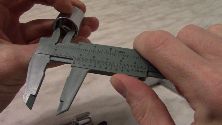
If the device is adjusted correctly, then the risks should match. Otherwise, it is necessary to contact a specialized center, where they will calibrate and adjust the device, on the basis of which a certificate of the established form will be issued. With regular use of a caliper, verification is performed at least once a year. If the metal of the working jaws is worn out, the tool becomes unusable and must be replaced with a new one. To increase the service life of the device, it is necessary to keep it clean and store it only in a case or case.

What it is?
This device is structurally similar to the more well-known tool - a caliper. It has a narrower specialization than the latter, and is intended only for linear measurements of grooves, grooves and ledges in one direction - in depth. For this reason, the depth gauge does not have sponges.
Measurement is carried out by inserting the end of the measuring rod into the groove, the depth of which must be determined. After that, you should move the frame along the main scale on the rod. Then, when the frame is in the correct position, you need to determine the readings in one of three possible ways (see below).

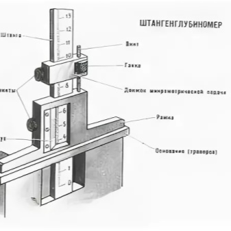
There are 3 types of readings from the device, according to three corresponding modifications:
- by vernier (depth gauges of the SHG type);
- on a circular scale (SHGK);
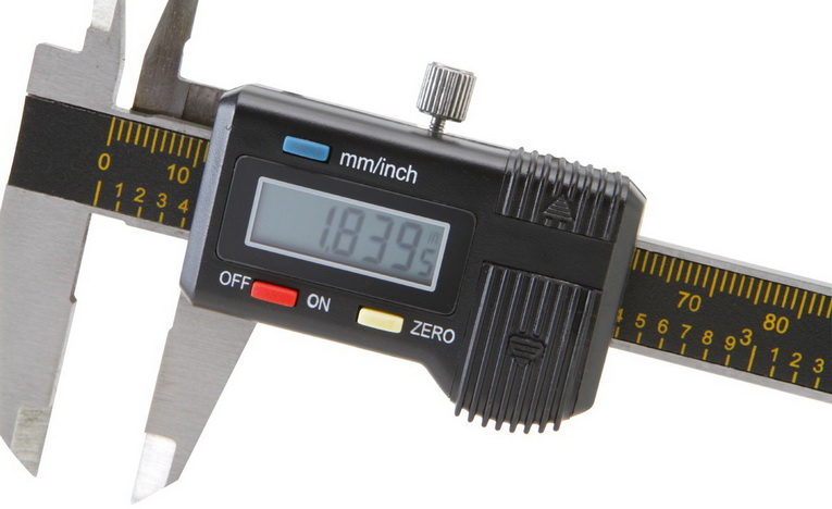
- on a digital display (SHGTs).
According to GOST 162-90, devices of the three listed types can have a measuring range of up to 1000 mm. The common ranges are 0-160 mm, 0-200 mm, 0-250 mm, 0-300 mm, 0-400 mm and 0-630 mm. When buying or ordering a depth gauge, you can find out its range by the corresponding conventional marking. For example, a model measuring a depth from 0 to 160 mm with a reading on a circular scale will have the designation SHGK-160.
Depending on the device device, important parameters, also regulated by GOST, are the following.
- Vernier reading values (for modifications of the ShG type). Can be equal to 0.05 or 0.10 mm.
- The division of the circular scale (for ShGK). The set values are 0.02 and 0.05 mm.
- The discreteness step of the digital reading device (for ShGTs). The generally accepted standard is 0.01 mm.
- Measuring frame length. Not less than 120 mm. For models with a measuring range up to 630 mm or more, the required minimum is 175 mm.
In the technical conditions established by GOST, the accuracy standards of this device are determined.For devices with vernier, the margin of error is 0.05 mm to 0.15 mm, depending on the measuring range. Devices with a circular scale have a permissible error of 0.02 - 0.05 mm, and digital ones - no more than 0.04 mm.
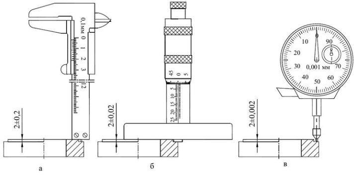
The device and the principle of operation.
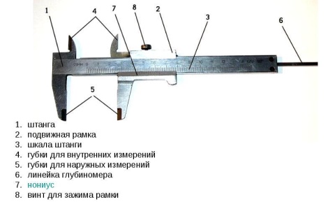
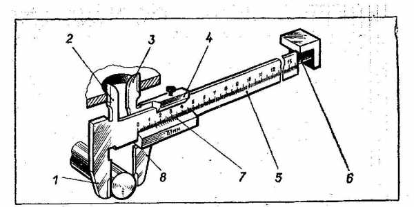
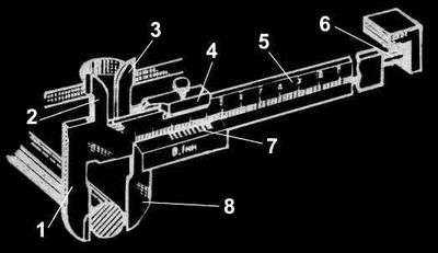
5.1. The caliper has two scales and a micro-screw device for fine adjustment of the frame. The main scale is marked on the bar with 1 mm divisions, the second scale is on the vernier, which is fixed on the frame. The frame is fixed with a locking screw. Smooth movement of the frame is provided by a spring located inside the frame.
5.2. The outer dimensions are measured with the lower jaws. The upper jaws are used to measure internal dimensions. Both pairs of jaws are used for marking work.
5.3. The dimensions are counted by the method of direct assessment of the coincidence of the scale division with the vernier divisions.
Fig. 1. Measurement scheme
5.4. Measurement using a vernier caliper of various structural elements (hole or shaft diameters, center-to-center distance, hole depth, etc.) is carried out as follows: with the screw 5 unlocked, move the vernier 6 along the rod 1, bring the measuring surfaces of the rod into contact with the surfaces of the parts being measured, and vernier 2 and 3 or a measuring rod 7 connected to vernier 7. In this position it is necessary to lock the frame of vernier 6 with screw 5 and remove the reading from the scale of the device.
Practical examples
The quality of the measurement depends both on the individual qualifications of the specialist and on the ability of the human eye to evaluate the object of measurement. It is for this reason that the accuracy class of calipers is limited to 0.05 mm division - a smaller vernier scale is hardly perceived by sight and can lead to an error. Although there are also calipers of increased accuracy - up to 0.02 mm. The main scale of this device has a graduation of 0.05 mm.
Measurement examples:
- Measurement of the outer diameter of the sleeve. The integer number of divisions of the main scale is 33, the coincident line of the vernier is 0.05. The outer diameter of the sleeve is 33.05 mm.
- Measurement of the inner diameter of the sleeve. The result is 27.30 mm.
- The check is carried out by measuring the wall thickness - 2.80 mm. Recalculation for the first two measurements gives (33.05-27.30) / 2 = 2.90 mm.
- Measurement of the height of the sleeve with the tool jaws - 40.40 mm.
- Measurement of height with a depth gauge - 40.40 mm.

What explains the resulting error of 0.05 when measuring the wall thickness? There are three reasons:
- tool error;
- workmanship of the part. The bushing was not deburred during parting off, which led to an unreliable result when measuring the inner diameter, and the measurement result should force the turner to correct this deviation;
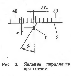
- the third reason is precisely formulated by the great creator of the Renaissance Michelangelo: "The compass should be in the eye, not in the hand, for the hand works, and the eye judges." When measuring, the depth gauge could be installed not strictly vertically, the resulting measurement would turn out to be unreliable.
The tool manual prescribes simple rules on how to correctly measure with a caliper - when measuring (including depth), the tool must be installed strictly along or perpendicular to the axis of the part, the jaws must be firmly pressed against the measured surface, and the carriage must be fixed with a screw.
 The online manuals of the machine builder available to everyone indicate that the above dimensional tolerances of ± 0.3 and ± 0.15 mm for shafts in the range of sizes from 50 to 1000 mm correspond to accuracy qualifications from h8 to h12. According to these qualifications, irrelevant parts of equipment and machines are made - bushings, axles, flanges, covers. Using a vernier caliper, it is impossible to grind the shaft journal for the bearing fit with a K6 quality and a tolerance of up to +0.02 mm.
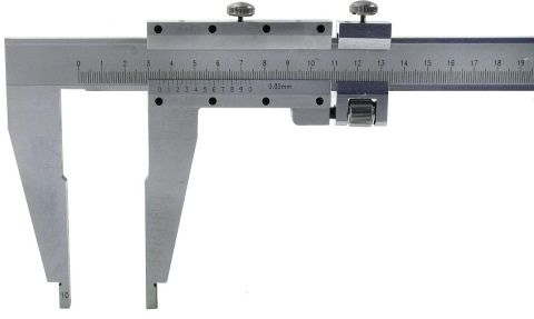
In the manufacture of parts within 8-12 accuracy classes, other modifications and types of calipers are used. The depth gauge instead of the jaws is equipped with support legs for installation on the edges or shoulders of the holes.The height gauge carriage with an installed scribe allows it to be used for marking height dimensions.
By the totality of its characteristics, the caliper found its place in heraldry and emblemology, characterizing its presence on the coats of arms of some cities or on the emblems of departments and structures as a symbol of technical armament.
Originally posted 2018-04-06 09:29:21.
Selection Tips
The acquisition of any measuring instrument is a very important and responsible matter, therefore, its choice must be approached with special care.
The first thing you need to pay attention to when buying a device is the accuracy class and the conditions in which the tool is supposed to be used.
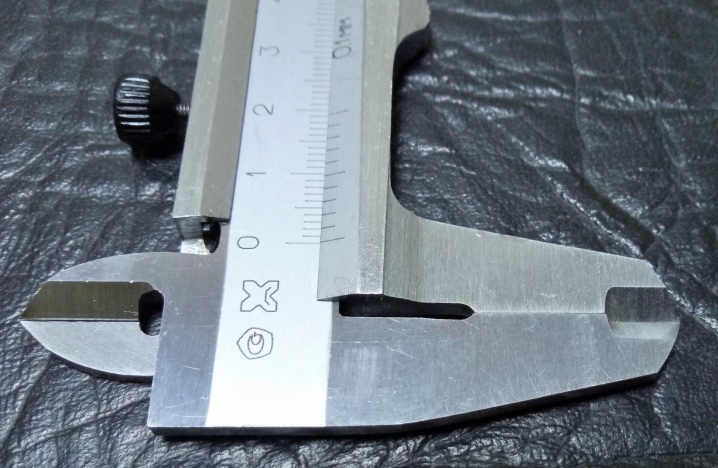
When buying a caliper designed for fine jewelry work, it is better to stop at short miniature samples 12-15 cm long. It is much more convenient for them to measure small objects without fear of damaging their surfaces.
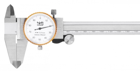
If in the first place is the convenience of the work performed, as well as the speed of measurements, then it is better to opt for an electronic-digital or dial-pointer model. As for the accuracy class, for domestic use, a device with a readout of 0.1 mm is quite sufficient, and for professional samples a much higher accuracy is required: the reading scale on such devices should have a step of 0.05, 0.02 and even 0.01 mm.

The next important criterion will be the choice of the manufacturer. Experts recommend purchasing products of well-known brands, which will act as a guarantor of the reliability, accuracy and high quality of measuring instruments. If measurements are planned to be made in difficult external conditions, it is better to purchase a device on which the scale will be engraved on the metal, and not painted with paint. The best professional models are German, Japanese and Swiss models, which, in principle, cannot be cheap. But such a caliper will last more than a dozen years and will be inherited by the grandchildren.
At the time of purchase, you should check the availability of accompanying documentation indicating the accuracy class and steel grade, as well as make sure that there is no play between fixed and moving parts. In addition, the zero marks of both scales must be the same when the jaws are tightly pressed together. In case of incorrect operation of the tool, too tight or, on the contrary, easy movement of the measuring frame and jaws, as well as in the presence of defects and damage, the purchase of the device should be abandoned.
How to use a caliper, see below.
How to take readings?
The most interesting question with regards to working with a caliper is the removal of the values obtained as a result of measurement.
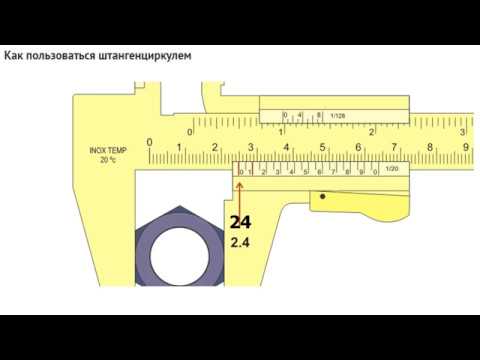
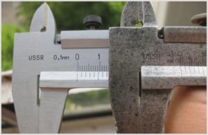
This article discusses a vernier caliper with an accuracy of 0.1mm. That is, he can measure the dimensions of a part with an accuracy of a tenth of a millimeter.
Consider the process of reading the readings of the caliper when measuring the outer diameter of the pipe, which we performed above (see item 1).
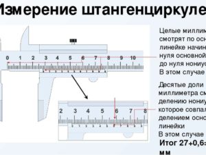
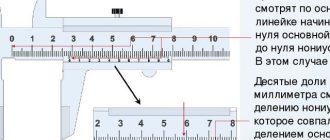
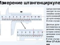
In order to determine the whole number of millimeters, we must look at what value on the barbell scale corresponds to zero risk on the vernier scale. We see that zero risk is between 26 and 27 mm on the main scale. That is, the outer diameter of the pipe is 26 mm, but tenths still need to be determined.
To do this, we need to see which of the risks on the vernier scale most closely matches the risks on the barbell scale
We see that it is the seventh risk of vernier that most closely matches the risk on the main scale (in this case, from four centimeters, but the value of the main scale is unimportant), so the number of fractions is 0.7 mm
Thus, the outer diameter of the pipe is 26 + 0.7 = 26.7 mm, which is absolutely correct, since this is an imported pipe with a diameter of ¾ inch, which corresponds to the value we obtained in millimeters.
The rule for determining the size with a caliper can be formulated as follows:
An integer number of millimeters in size is determined by the value of the risks on the bar scale located to the left of the zero risk of the vernier, and fractions of millimeters are determined by the value of the risks of the vernier, which most closely matches the risk on the main scale. If the zero risk of the vernier scale exactly coincides with any risk on the millimeter scale of the rod, then the size value is expressed as an integer
Why Measurement Errors Occur
The most common mistakes that reduce the accuracy of measurement results with a serviceable instrument:
- Excessive pressure on the frame will cause it to skew relative to the boom. The same effect is obtained if, when measuring with the lower jaws, the vernier caliper is brought down by the upper ones.
- Installation of jaws on fillets, chamfers and fillets.
- Positioning skews.
- Abnormal instrument calibration.
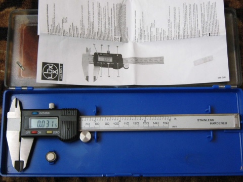
The first three mistakes most often arise from lack of experience, and go away with practice. The latter must be prevented at the stage of preparation for measurements. The easiest way is to set "0" on the electronic caliper: for this there is a button (in Fig. 6, the "ZERO" button). The hour indicator is reset to zero by turning the screw located at its bottom. To calibrate the vernier, loosen the screws fastening to the frame, move it to the desired position and fix it again.
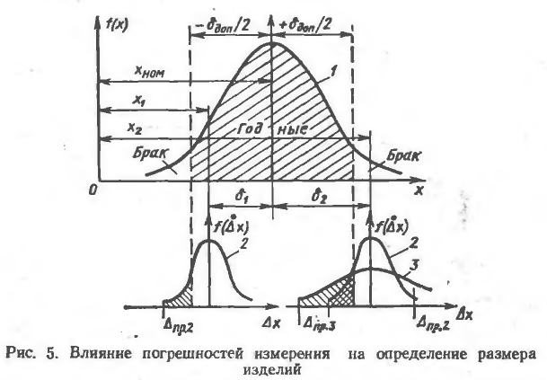
Deformations of the caliper elements and wear of the measuring surfaces make the tool unusable. To reduce the number of rejects in production, calipers undergo periodic verification in metrological services. To test the accuracy of the tool and acquire skills in the domestic environment, you can measure parts whose dimensions are known in advance, for example, drill shanks or bearing rings.

