Sinus vise
Sinus vise is designed to fix the workpiece at the required angle with respect to the plane of the table. To calculate the installation of a certain angle, a formula is used by which the height of the spacer is determined, due to which the required angle is achieved. In the calculations, an indicator is used - the sine of the angle on the basis of which this type of device is named. A KID (gauge block) is used as a spacer.
To set a certain angle, special sinus tables can be used, on which devices for carrying out working operations are attached.
There is and is used a method of installing a part at an angle using angular measures. But this method is used when it is necessary to process only at a slight angle.
A method has been developed using magnetic sinus tables, where the processing angle is set by adjusting the table tilt angle using electromagnets. Magnetic steel tables are mainly used for surface grinding and high-precision cutting.
When carrying out the most complex types of processing, 3-axis angular steel devices are used with the help of which the fixation of the workpiece is adjusted in 3 planes and at any angle. The devices are capable of fixing the workpiece in the planes: 1. ± 45 °; 2.from 0 to 90 °. With respect to the base, the angle of rotation of the workpiece can be changed from 0 to 360 °.
In special cases, you can use a double vice with fixing two workpieces at once.
Using devices on a mobile platform
The principle of operation of devices of this type is to use a movable base. The base is able to move in 2 planes, which significantly expands the possibilities of processing parts of especially small size requiring special precision.
When processing large workpieces that do not fit between the jaws, special steel clamps are used, which are attached to the machine table and the workpiece is placed between them and rigidly fixed. In one of the clamps, the jaw is installed using an adjustment mechanism, which allows the final fixation of the workpiece.
Construction device
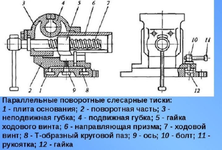
At the heart of any machine vice, there are a number of basic elements:
- steel strips at the base of the vise;
- movable and stationary jaws, which directly clamp and hold the workpiece during operation;
- a handle with a screw to control the entire structure, changing the position of the jaws;
- additional plates and fasteners to ensure the integrity and reliability of the vice during operation.
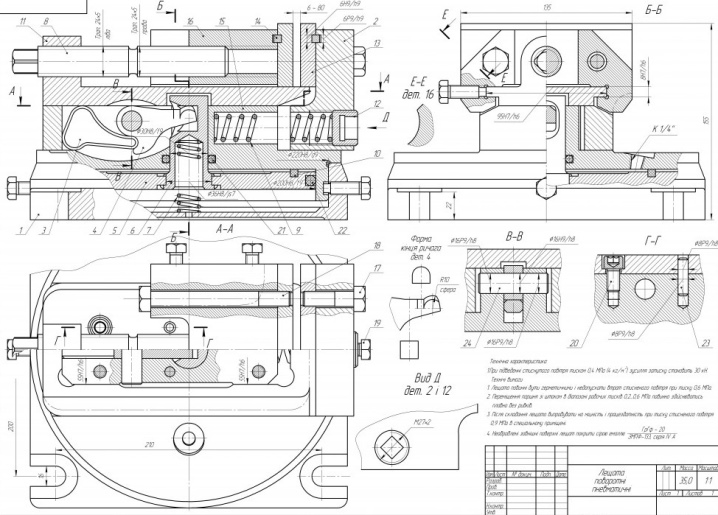
All other parts of the vice are fixed with the help of the main strips. This is a kind of foundation that ensures the work of the vice during the entire operational period. Therefore, a hard and durable metal is selected for them. In the indicated place, a hole is drilled for a screw for the future fastening of the jaws. A small steel plate is installed at the bottom of the movable jaw - this makes it possible to fix their movement and reliably protects them from jumping off the grooves.
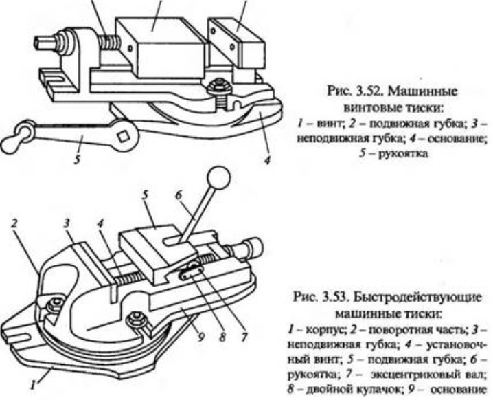
The sponge moves, thereby providing a clamp between the movable and stationary parts. But the effect of the screw in different models may differ - it all depends on the features of the chosen design. Simple models connect the screw and the movable jaw directly to each other. Clamping is provided either due to the fact that the screw pulls the sponge behind it, or repels it during movement.The concept will differ depending on which direction the propeller is turning.
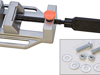
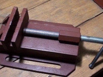
As for the rotary models, to facilitate the work, the energy for the screw is supplied through several gears connected to each other in several lines. In this case, the master does not need to apply too much effort during the processing of heavy and massive workpieces. This is just one example of a more complex design.
Technical requirements according to GOST
The vise uses durable materials such as alloy steel or cast iron. All products must comply with GOST 16518-96. According to GOST, there are rotary and non-rotary machines with different sizes of maximum stroke and groove. In accordance with the technical requirements, the vise can be of the following accuracy classes:
- Normal accuracy (N).
- Increased accuracy (P).
- High precision (B).
Parts of the movable vise must move smoothly, without jerking and not jam. The surfaces of the vise must be free of defects such as cracks, dents, corrosion. Requirements apply to surface roughness, the price of division of the circular scale in the rotary vise, service life, accuracy resource, vise safety.
Specifications.
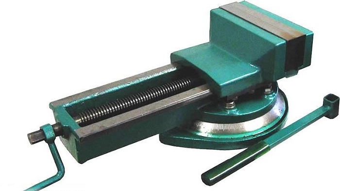
2.1. The vise is manufactured in accordance with ISO9001. Body parts material - hardened alloy steel 35L. The design of the fixed vise allows the installation of several vices next to each other, as well as on three mutually perpendicular supporting surfaces (bottom, side). The high hardness of the working surfaces ensures the durability of the vice while maintaining accuracy. The vise is equipped with a feed mechanism with an integral bearing and an articulated arm for easy handling of the vise.
2.2. The main parameters and dimensions of the vice are shown in table 1.
Table 1 - The main characteristics of the machine vice
| Parameter | Model | ||||||||
| QH80 | QH100 | QH125 | QH160 | QH200 | QB100 | QB200 | QB250 | QB320 | |
| Jaw width, mm | 80 | 100 | 125 | 160 | 200 | 200 | 250 | ||
| Jaw height, mm | 25 | 32 | 38 | 45 | 56 | 75 | |||
| Spreading interval L, mm | 63 | 100 | 112 | 140 | 190 | 245 | |||
| Spreading interval L3, mm | 174 | 215 | 250 | 305 | 385 | 500 | |||
| Spreading interval L4, mm | 220 | 265 | 305 | 375 | 470 | 615 | |||
| Groove width A for fastening, mm | 12 | 14 | 14 | 18 | 18 | 14 | 22 | ||
| Screw square width, mm | 12 | 14 | 14 | 18 | 18 | 22 | |||
| Bolt diameter, mm | M12 | M12 | M12 | М16 | М16 | M12 | М16 | М16 | M20 |
| Division value of rotation | 1º | 1º | 1º | 1º | 1º | 1º | 1º | 1º | 1º |
| Dimensions, mm | 256×80×74 | 305×100×86 | 345×125×98 | 345×125×98 | 517×200×135 | 656×250×168 | |||
| Weight, kg | |||||||||
2.5. Accuracy standards are given in Table 2. Accuracy class of machine vice - P according to GOST 16518
Table 2 - Accuracy characteristics of basing workpieces in a machine vice
| No. pp | Control scheme | Description | Permissible error, per 100mm base length |
| 1 | 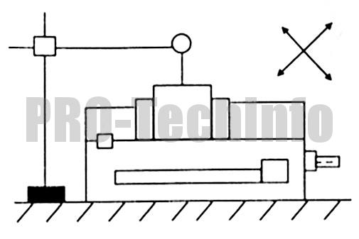 |
Parallelism of the upper guide surface to the base of the vise | 0,01 |
| 2 | 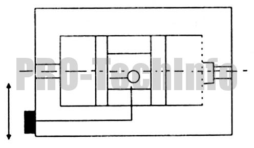 |
Perpendicularity of either fixed jaws or repositionable jaws to the upper guide surface | 0,03/100
(a≤90 °) |
| 3 |  |
Perpendicularity of fixed longitudinal groove jaws |
0,015/100 |
| 4 | 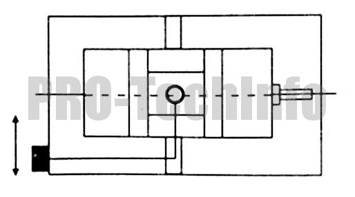 |
Parallelism of the fixed jaws of the transverse groove on the vise body | 0,015 |
| 5 |  |
Parallelism of the upper part of the vise and the lower part of the vise body | 0,02 |
| 6 | 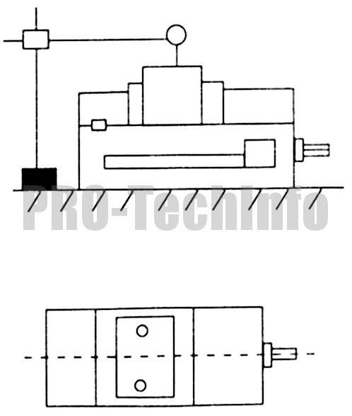 |
Lifting the measuring unit | 0,015 |
| 7 | 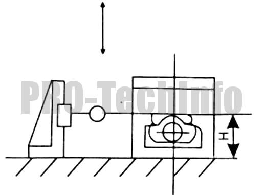 |
Perpendicularity of both sides to the base of the vise | 0,01 |
| 8 | 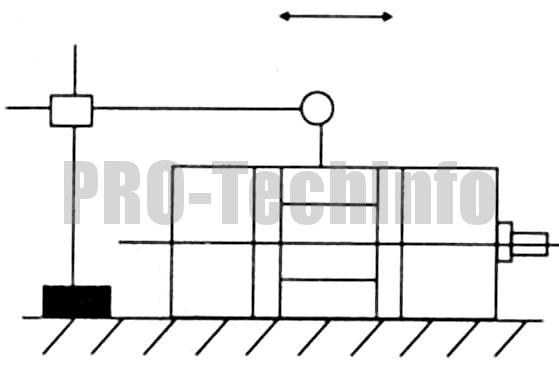 |
The parallelism between the two sides of the vise jaws in the longitudinal direction | 0,01 |
Accessories for special types of work
When carrying out work related to the processing of pipes of various diameters, as well as circles, devices are used that have a mechanism for fixing pipes with the ability to adjust.
In production where wood or plastic is used as a material, devices with an eccentric clamping mechanism are used to ensure fixation of parts with a moderate adjustable force.
If it is necessary to fix the workpiece at an angle of 90 °, special vices are used to ensure the required angle of fixation and processing of the workpiece.
Varieties and purpose
The main components of the vice are two jaws that are opposite each other. One jaw is tightly fixed, and the other moves, thereby clamping the part.A milling vise is used to move a part face-to-face to a master, to create a circular part, or to move a workpiece 90 degrees. They are used both in private small workshops (for example, for the manufacture of accessories), and in large industrial production for the manufacture of complex parts. In terms of functionality, the milling vice can be divided into rotary and non-rotary.
Swivel
Such machine vices are the most popular. They allow you to change the angle of inclination of the part during its processing, thereby eliminating the need to fix the workpiece in a new position. However, there are also disadvantages here. The high mobility of the part adversely affects its fixation. But this disadvantage, as a rule, is compensated by other parameters, for example, a decrease in revs.
Important!
Milling rotary vices in small workshops are mainly used for making small items such as furniture fittings or keys. In large manufacturing plants, such devices are used to make engine parts or other products that have a complex shape.
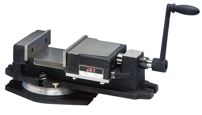
The rotary vise can be manual, pneumatic or hydraulic. The base of the manual rotary vise is a rotary disc, with the help of which the vise is rotated together with the material clamped in them. On such a disc, a hand vise is fixed with bolts. The distance between the jaws of the vise is manually adjusted. Such a vice is used mainly in small workshops and for processing fragile objects. They are inexpensive and very practical.
There is also a rotary disc at the base of the pneumatic vise. The vise attached to it consists of two plates and a rail. A sealed tube is attached to the movable vise plate at one end. The other end of the tube is connected to a pump, which can be electric or manual. The clamping force of the vise is regulated by the pump, which supplies compressed air through the tube.
Hydraulic vise repeats the principle of pneumatic vise, then with the only exception that instead of air, liquid is supplied through the tube. Typically, water is used, but more viscous fluids are used to enhance compression. The hydraulic vise is the most popular type and is most commonly used in manufacturing.
Fixed
Fixed milling vise, judging by its name, does not have a swivel mechanism
But despite the fact that they lack such an important function, the non-swivel vise is a worthy competitor for the swivel. The thing is that fixed vices are much cheaper than rotary ones, therefore they are in good demand.
Fixed vices are also manual, pneumatically and hydraulically driven.

