Quality problems of produced wires
Many manufacturers of cable and wire products, trying to help out more, artificially underestimate the thickness of the insulation and overestimate the diameter of the cable. By specifying a wire cross-section greater than in reality, the manufacturer saves a very large amount. For example, the production of thousands of meters of copper wire with a cross section of 2.5 mm2 requires 22.3 kg of copper, while the manufacture of a wire of 2.1 mm2 requires only 18.8 kg. So we get a saving of 3.5 kg of copper.
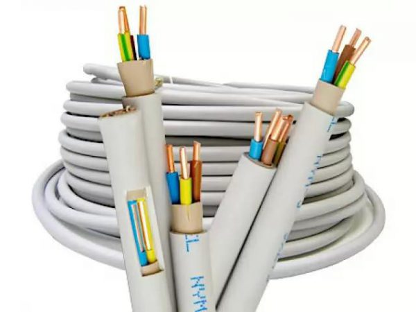
Another way to reduce the cost of production is to manufacture a conductive core from low-quality raw materials. By adding cheap impurities, the conductivity decreases, therefore, the calculations of the cable length must be changed.
Determination of the diameter at home
The need to find out the exact diameter arises only in 2 two cases - there is no marking on the outside or the absence of conditionally control items with a known section (fittings, adapters). By marking, you can determine all the parameters - purpose, material of manufacture, wall thickness. With the help of fittings, adapters, they find out if a particular pipe is suitable for water supply, heating.
You can take measurements at home using a ruler (tape measure), caliper, micrometer. The accuracy of the results obtained depends on this. You can use other means - a thread, a box of matches or any object, the dimensions of which are known and do not exceed the cross-section of the pipeline.
How to measure with a caliper?
It is a universal measuring device with which you can find out all dimensions of the pipeline.
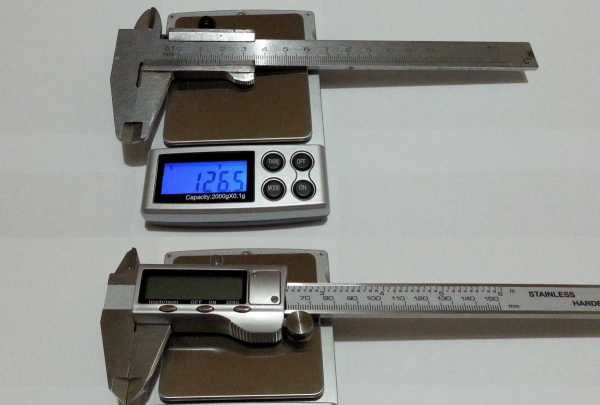
In addition to the maximum and minimum values, they differ in the ways of taking the results:
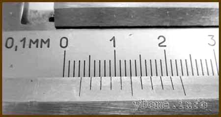
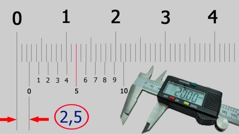
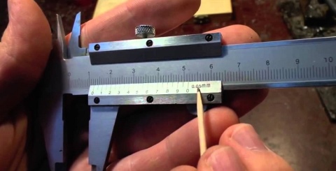
- In vernier (SHTs), millimeters are plotted on the main scale, and fractions of mm on the auxiliary one. When the rod moves, the pointer stops at a certain value.
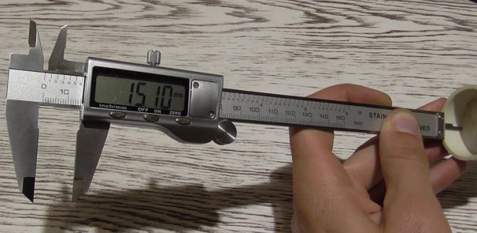
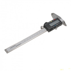
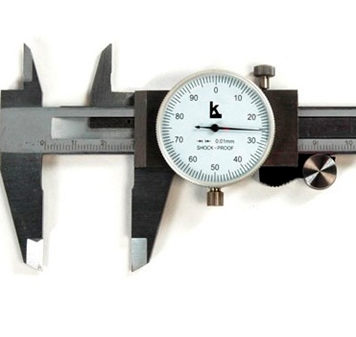
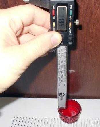
- Dial (ShTsK) are needed for more accurate measurements. The mm shares are indicated by a dial connected to the gear bar. In digital (SCH), the value is displayed on the LCD screen.
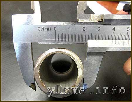
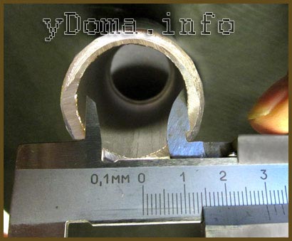
How to measure the inner diameter of pipes using a vernier caliper:
- Clean the inner surface from dirt, dust.
- Move the jaws of the boom to the zero position.
- Install them in the hole.
- Dilute the jaws to the stop, trying to obtain the maximum value.
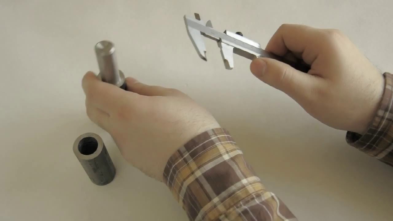
To measure the outer section, you need to dilute the jaws of the caliper and place them between the pipeline. To get an accurate result, you need to apply a little pressure. Repeat the procedure 2-3 times.
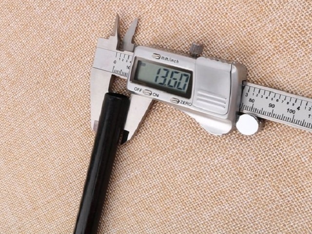
Before starting work, it is recommended to check the accuracy of the caliper readings by taking the dimensions of a standard object with known dimensions or cross-section.
We measure with a micrometer
The tube micrometer is convenient for quick reading of external dimensions. If you need to know the inner diameter, you should measure the wall thickness. Unlike vernier calipers, most micrometer models give more accurate results, the average error is 3-5 microns.
 Micrometer application
The procedure for conducting internal measurements:
- Install the pipe between the heel and the spindle, take readings.
- Also find out the wall thickness.
- Subtract 2 thickness readings from the outer dimensions.
The disadvantage of the device is the limitation on the maximum size. To increase the accuracy, special attachments are used. When performing calculations, the dimensions of the nozzles must be added to the obtained indicators.
Laser sensors
The principle of operation of laser sensors is based on scanning the surface with a laser beam. The rate at which radiation returns to the photodetector determines the distance traveled.To improve accuracy, the working head rotates, which makes it possible to take a large number of measurements per second. Such devices are used only in mass production, where it is important to control the uniformity of the wall thickness over a certain length.
Working principle of tube laser sensors:
- The measuring part of the device is placed inside the cavity.
- Fixation with clamping rollers.
- Several series of measurements at different sections of the highway.
- Reconciliation of data.
The advantage of the method is maximum accuracy and the ability to take measurements at different depths, remotely. The disadvantage is expensive equipment. It is only used in the manufacturing process or for large quantities of pipes used where accuracy is important.
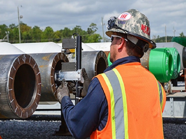 Measuring the pipe diameter with a laser sensor
All about the diameter of the reinforcement
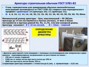
Rebar manufacturers often use worn-out equipment, and the rebar is slightly larger than the required diameter.
Rebar manufacturers often use worn-out equipment, and the rebar is slightly larger than the required diameter. According to the tolerances, it passes, and the total tonnage corresponds, and in terms of running meters, a shortage is formed. In search of these meters, time is lost, the project stops and the feeling of deception remains.
When trying to determine the diameter of the reinforcement, it should be borne in mind that the cross-sectional shape of the reinforcing bar looks more like an ellipse than an even circle. Therefore, by measuring the bar in different places, a person gets a series of numbers. In addition, taking measurements along the body of the bar and along the ribs, the run-up in terms is obtained in several millimeters.
This confuses the calculations.
How to determine the diameter of the reinforcement?
The size should be seen in the accompanying documents. In them, manufacturers put down the so-called nominal diameter of the reinforcement, it is called the number of the reinforcement. This indicator indicates what size the rod was from which this piece of reinforcement was made (taking into account some assumptions).
That is, the profile number of the original blank is comparable to the nominal diameter of the finished product. As a result, you can do the following (you need a caliper):
- Measure the body of the bar.
- Measure the diameter of the protruding ribs.
- Sum up the indicators and divide the result by 2.
Many do so. Get an average that suits everyone.
The option is unprofessional, it works at the everyday level, since professionals do not ask such questions. In such calculations, the following expressions are appropriate: “maximum reinforcement diameter” and “minimum reinforcement diameter”.
These are exactly the two indicators that were obtained when measuring the body and the edge of the bar.
Using these figures, a table was developed in which it is prescribed what are the minimum and maximum dimensions, what nominal diameter of the reinforcement correspond to.
Rebar diameter. Diameter ratio table
| nominal diameter | maximum diameter | minimum diameter |
| 6 mm. | 6.57 mm. | 5.57 mm. |
| 7 mm. | 7.75 mm. | 6.75 mm. |
| 8 mm. | 9 mm. | 7.5 mm. |
| 9 mm. | 10 mm. | 8.5 mm. |
| 10 mm. | 11.3 mm. | 9.3 mm. |
| 12 mm. | 13.5 mm. | 11 mm. |
| 14 mm. | 15.5 mm. | 13 mm. |
Rebar weight
When selling fittings, the price is indicated per ton of the product. Starting a small-scale construction, a person calculates the length of the rod required for the project.
Any fittings that comply with GOST have fairly accurate weight indicators per 1 running meter of a rod. These data are also entered in the table and are actively used at metal warehouses.
The ratio of the minimum, maximum and nominal diameters corresponds to a specific weight indicator. This helps to determine the weight of the reinforcement by diameter.
Rebar diameter for foundation
Having prepared the trench for placing the support base of the object under construction in it, it is time to calculate the required diameter of the reinforcement. You can, of course, take a thicker rod and a larger quantity. But this will increase the cost of materials and leave an impression of amateur performance.
Better done by science
In addition, there is everything you need for this. And above all the table.
| Valve No. | Number of bars and cross-sectional area | |||||
| 1 PC. | 2 pcs. | 3 pcs. | 4 things. | 5 pieces. | 6 pcs. | |
| 6 | 28.3 mm2 | 57 mm2 | 85 mm2 | 113 mm2 | 141 mm2 | 170 mm2 |
| 8 | 50.3 mm2 | 101 mm2 | 151 mm2 | 201 mm2 | 251 mm2 | 302 mm2 |
| 10 | 78.5 mm2 | 157 mm2 | 236 mm2 | 314 mm2 | 393 mm2 | 471 mm2 |
| 12 | 113.1 mm2 | 226 mm2 | 339 mm2 | 452 mm2 | 565 mm2 | 679 mm2 |
It is necessary to measure the future foundation and calculate its cross-sectional area. If we take the height and width of 600 and 500 mm. The multiplied values will give a result of 300,000 mm2. For such a foundation, the cross-sectional area of the reinforcing rods from the cross-sectional area of the foundation will be 0.1%. That is, 300,000: 100 x 0.1 = 300 mm2. This is the cross-sectional area of all rods. The closest readings in the table suggest a value of 302 mm2. This corresponds to 6 bars No. 8. The transverse reinforcement can be of lesser thickness, but not less than 6 mm. Better to take the same 8 mm. Using tables, you can effectively calculate the parameters of the future foundation and not incur unnecessary costs.
New product notifications
I want to receive
How to check a vernier caliper for accuracy?
Asking the question of how to use an old caliper, remember that the correct results can only be removed from a proven instrument.
Once a year, professional calipers are sent for inspection, and before using, even at home, it is better to pay attention to the main possible inaccuracies
The first step is to check the coincidence of the zero line and the presence of a gap between the shifted jaws.
On a flat surface, check the zero line with a depth gauge.
It is important that the carriage of the movable jaw does not move at the inclination of the caliper.
In the electronic model, much depends on the timely change of the power source.
It is not bad to find out the accuracy class of the caliper, since it is sometimes necessary to determine some measurements as reliably as possible. The first type refers to the so-called household calipers, when there is enough reading of 0.1 mm
For more accurate measurements, tools of the second and third types are needed, where the reading value is already 0.05-0.01 mm.
Technology
§ 17. Measuring the dimensions of parts with a vernier caliper
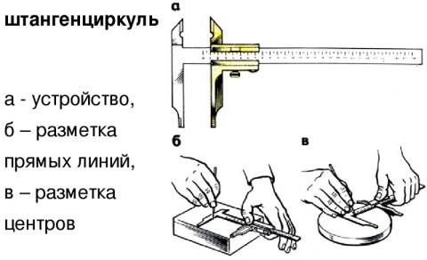
In the manufacture of parts from thin sheet metal and wire, you can use the simplest control and measuring tools: a ruler, bench square, etc. Calipers are used to measure and control parts with greater accuracy. They are designed to measure the outer and inner dimensions of parts and the depth of holes, grooves, grooves. Calipers are of different types and differ in the limits and accuracy of measurement.
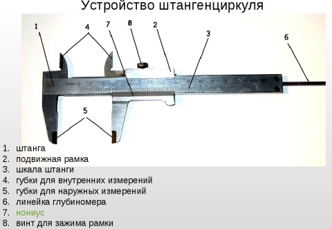
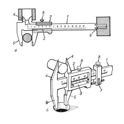
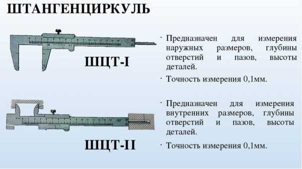
Figure 63 shows a vernier caliper ШЦ-1 with measurement ranges from 0 to 125 mm and an accuracy of 0.1 mm. It consists of a bar 1 having a scale of 6 with millimeter divisions. A movable frame 4 moves along the bar, which can be fixed in the desired position with a clamping screw 3. A depth gauge 5 is attached to the frame.
Rice. 63. Vernier caliper ШЦ-1: 1 - bar; 2 - jaws for internal measurements: 3 - clamping screw for fixing the frame; 4 - movable frame; 5 - depth gauge; 6 - barbell scale; 7 - vernier; 8 - sponges for external measurements; 9 - measured parts
The lower jaws 8 are used to measure the outer dimensions, the upper 2 - to measure the inner dimensions. The depth gauge measures the depth of the grooves and holes.
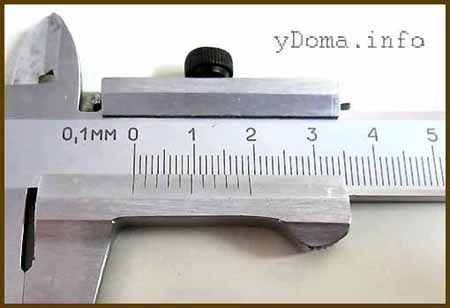
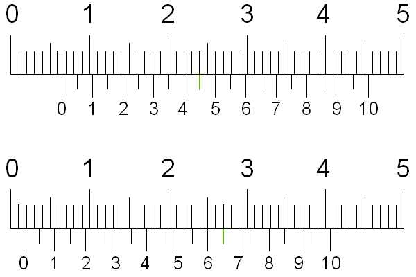
How is it possible to measure tenths of a millimeter if the scale of a caliper has millimeter divisions? An auxiliary scale called vernier 7 serves for this purpose. The vernier is 19 mm long. The vernier is divided into 10 equal parts, therefore, the price of each division is 1.9 mm.
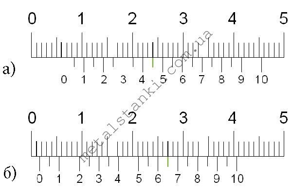
When the jaws are closed, the zero strokes of the barbell and vernier scale coincide (Fig. 64), and the tenth stroke of the vernier is aligned with the nineteenth stroke of the millimeter scale.
Rice. 64. Barbell scale and vernier
Please note that the first stroke of the vernier does not reach the second stroke of the barbell scale by exactly 0.1 mm (2 - 1.9 = 0.1). This allows you to make measurements with an accuracy of 0.1 mm.
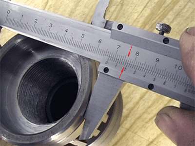
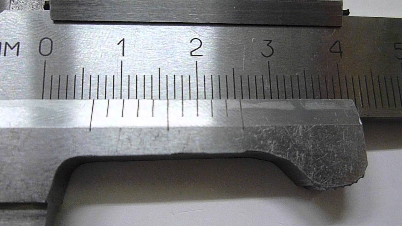
When measuring with a vernier caliper, an integer number of millimeters is counted on the millimeter scale of the rod to the zero vernier line.Tenths of a millimeter - on the vernier scale from the zero mark to the vernier stroke that coincides with any stroke on the millimeter scale (Fig. 65).
Rice. 65. Examples of measuring with a caliper. The position of the bar and vernier scale when measuring the dimensions: a - 0.4 mm; 6 - 6.9 mm; h - 34.3 mm
Remember! A caliper is an expensive measuring tool that must be handled with care.
Caliper Handling Rules
Before starting work, wipe the vernier caliper with a clean cloth to remove grease and dust.
Do not clean the tool with a sandpaper or knife.
Do not place the tool on heating devices.
You can measure only clean parts without scoring, burrs, scratches.
The jaws of the caliper have sharp ends, so care must be taken when measuring.
Do not skew the caliper jaws. Fix their position with a clamping screw.
When reading the readings on the measuring scales, hold the vernier caliper directly in front of your eyes.
In enterprises, a vernier caliper is one of the main measuring tools. It is used by workers of various specialties and inspectors of machine tools and locksmiths. Nowadays, calipers with digital indicators (battery-powered) are increasingly used, which allow you to measure parts with an accuracy of 0.01 mm.
Getting to know the professions
The inspector of the technical control department (QCD) is a specialist who is responsible for the quality of the manufactured parts at the enterprise. He watches that. so that the manufactured parts exactly match the drawings. This is a very demanding job, because if a defective part that does not correspond to the drawing gets into the product, the product will quickly fail. Quality control inspectors must know the rules for setting and regulating control and measuring instruments and devices, methods for checking the quality of surfaces, rules for accepting parts, etc.
Laboratory and practical work No. 17
Measuring the dimensions of parts with a vernier caliper
-
Make a sketch of the stepped roller issued by the teacher in your workbook (Fig. 66).
- Measure each roller size with a vernier caliper and record the results in millimeters on the table.
- Place the resulting dimensions on the sketch made in the workbook.
Rice. 66. Sketch of the part "stepped roller" (to items 1-3)
We test our knowledge
-
What are the main parts of a vernier caliper?
-
How many measuring scales does a vernier caliper have?
-
What measurements can you take with a caliper?
-
How many times the accuracy of measuring with a caliper exceeds the accuracy of measuring with a ruler?
- How do whole and tenths of a millimeter count using a caliper?
Measurement procedure, serviceability check
Before work, check the technical condition of the caliper and, if necessary, adjust it. If the appliance has skewed lips, do not use it. Also, nicks, corrosion and scratches on working surfaces are not allowed. It is necessary that the ends of the rod and the depth gauge with the combined jaws coincide. The instrument scale must be clean and legible.
Measurement
- The jaws of the caliper are pressed tightly against the part with little effort, without gaps and distortions.
- Determining the value of the outer diameter of the cylinder (shaft, bolt, etc.), make sure that the plane of the frame is perpendicular to its axis.
- When measuring cylindrical holes, the jaws of the caliper are positioned at diametrically opposite points, which can be found guided by the maximum readings on the scale. In this case, the plane of the frame must pass through the axis of the hole, i.e. measurement along a chord or at an angle to the axis is not allowed.
- To measure the depth of the hole, the bar is installed at its edge perpendicular to the surface of the part. The depth gauge ruler is pushed all the way into the bottom using a movable frame.
- The resulting size is fixed with a locking screw and readings are determined.
Working with a caliper, they monitor the smoothness of the frame. It should sit tightly, without swaying on the bar, while moving without jerking with moderate effort, which is regulated by the locking screw. It is necessary that with the jaws aligned, the zero stroke of the vernier coincides with the zero stroke of the bar. Otherwise, reinstallation of the vernier is required, for which they loosen its screws fastening to the frame, align the strokes and re-fasten the screws.
How can you measure the diameter with improvised devices
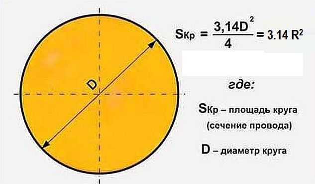
If you do not have a specialized tool at hand, and you still need to measure the diameter of the pipe, you can refresh your memory of the school formula for determining the circumference. Here it is: C = "pi" x d. Where:
- C - this is the circumference;
- "Pi" is a number with a fixed value, for convenience it is taken equal to 3.14;
- D is the diameter of the circle.
Therefore, in order to measure the pipe diameter, you need to divide the C value (circumference) by 3.14. But in this way it will be possible to measure only the outer diameter of the pipe.
Normal sewing tape is sufficient to determine the circumference.
An ordinary construction tape is taken, or a tailor's measuring centimeter, then it is wrapped one turn around the pipe. Care must be taken to ensure that the tape does not warp, but lies as flat as possible across the pipe. When the measurements are made, all that remains is to perform the calculations described above. For example, if it turned out that the circumference is 12 centimeters, then, dividing 12 by 3.14, the result is 3.8 centimeters. By the way, in this way, you can measure the diameter of not only the pipe, but also any other round object. If even a tape measure is not at hand, then you can use a not too thick cord or thread. It will be enough just to wrap the pipe with thread - and then attach it to the ruler. If you need to get more accurate values, then the number "pi" can be taken not for 3.14, but for 3.1416.
For example, if it was indicated that the pipe diameter is 2.4 inches, then multiplying this number by 2.54, you can get the result - 6.096 cm.If you need to do the reverse translation, then the value expressed in centimeters is divided by 2, 4. The above result of 3.8 cm would be 1.49 in inches.
Methods for measuring wire diameter
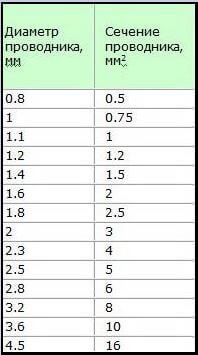
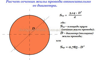
In order to calculate the cross-sectional area of a conductor, you need to know its exact diameter. There are several ways to measure the diameter of a wire. These include measurements:
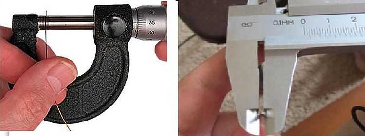
- Using a caliper: for this you need to understand the principle of operation of a caliper and be able to take readings from its scales. In this case, the use of an electronic measuring device makes it possible to simplify the measurements - it will show the exact value of the diameter on its screen.
- Using a micrometer: This meter is slightly more accurate than a mechanical caliper, but it also requires some skill to get correct and accurate readings.
- Using a regular ruler: this method is suitable for those who do not have such measuring instruments as a caliper or micrometer in their arsenal. Measuring the conductor diameter using a ruler will not be accurate enough, but it will be possible to roughly estimate the diameter.
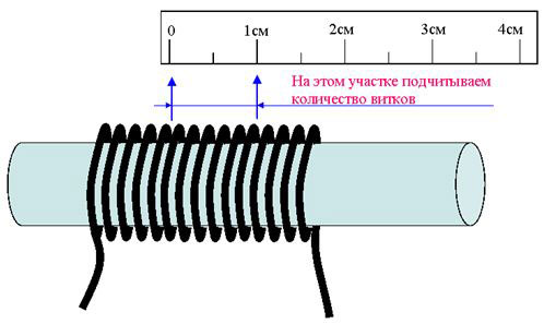
To measure the diameter of the conductor, first of all, it is stripped from the insulation with a knife or stripper. Further, if a micrometer or vernier caliper is used, the wire core is tightly clamped between the jaws of the device and the size of the conductor is determined according to the scales of the device. When using a ruler, the insulation is removed at a distance of 5-10 cm and the core is wound around a screwdriver. The turns of the conductor should be tightly pressed against each other (approximately 8-20 turns).Next, the length of the wound section is measured and the resulting value is divided by the number of turns - a more or less accurate diameter value will be obtained.
How does a digital caliper work?
There are three modifications of the caliper, they were divided according to the method of taking measurements.
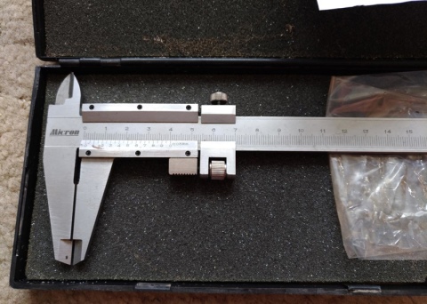
- The simplest vernier models can be used for household needs. Integer values are taken from the bar, the shares are determined by the vernier - these are the basic rules on how to use a caliper.
- The mechanical measuring principle is used in dial models. Through a gear train, fractions of a millimeter are transferred from the bar scale to the dial, integer values are taken from the bar.
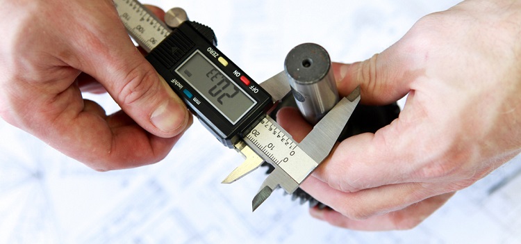
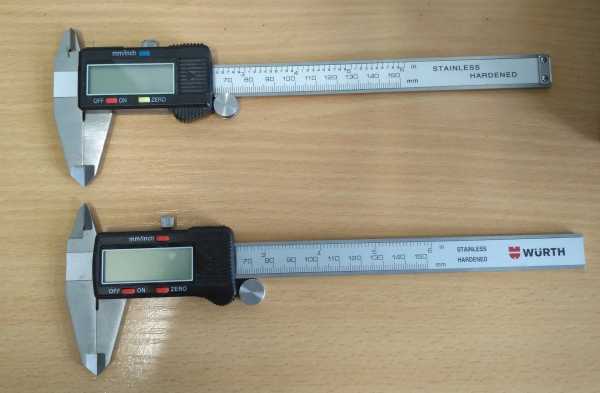
- The most convenient and accurate is the digital version, where all the results are obtained from the display screen. The electronic part itself can be configured, it is even more convenient to use.
To understand how to use it, you need to understand how a digital caliper works. The work is based on a digital capacitive vernier: inside the device there is a capacitive matrix, several plates, the main ones are the stator and the slider. When calculating them, they are displayed on the display, the stator is located on the mechanical ruler, and the rotor is under the display itself.
Instrument device
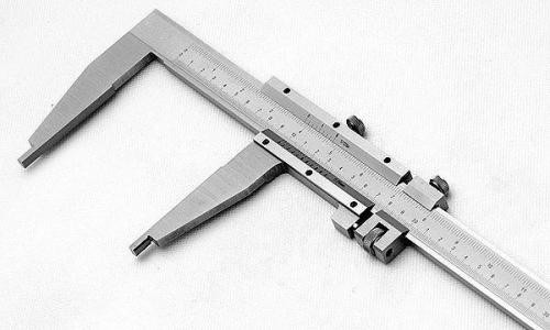
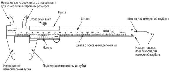
How to learn to use a caliper? To begin with, familiarize yourself with its device. Most of all, the manual caliper of the double-sided type, with a linear measuring system, which is in demand by production, consists of the following structural elements:
- Measuring rod, where there is a scale with divisions, the accuracy of which corresponds to the class of the tool.
-
Measuring frame sliding in the rod guides. How to use a vernier caliper? On the lower control surface of the frame, the vernier divisions are applied, according to which the mantissa of the measured value is determined: the size value after the decimal point. For example, when measuring the length of 13.9 mm with accuracy class II, the reading "13" will be taken from the main scale, and the reading "0.9" - from the vernier. For ease of use, the frame is equipped with a grooved projection on its lower right side.
- Lower measuring jaws of the rod body. They are designed to determine the external dimensions of a part or workpiece. The measuring planes of the jaws are internal, and their overhang is determined by the measurement limits for which this tool model is designed. According to the state standard, the protrusion of the lower jaws can be from 35 ... 42 mm to 63 ... 125 mm, depending on the measurement limits for which this model is designed.
- The upper measuring jaws of the rod body, with the help of which the dimensions of the outer surfaces of the products are determined. The control planes of the upper jaws are also calibrated, and their overhang, as in the previous case, is determined by the capabilities and type of the product. It ranges from 16 to 30 mm.
- Clamping screw with knurled head, with which the current position of the frame is fixed.
- Depth gauge, which is a flat ground pin sliding in guides located on the opposite side of the rod body. There is a tapered bevel on the working end of the pin in order to reduce the dimensions of the end surface of the depth gauge. This makes it possible to estimate the depth of holes with small diameters.

Instrument device
All contact edges of the rod, guides, frame and vernier are carefully ground to size, with an accuracy an order of magnitude higher than that with which a vernier caliper operates.
Other elements may be provided for special design requirements. Auxiliary measuring surfaces (and, consequently, nodes) are necessary if marking operations, determination of the dimensions of ledges, stepped parts of structures, etc. are performed. Sometimes a micrometric frame feed is built into the tool.
How to work?
In order to work correctly with a caliper, you need to understand how to read the readings. Everything here is a little more complicated than with a simple ruler.The fact is that the instrument has two scales. The first (main) is millimeter. It gives the initial measurement data. The second (aka vernier) will help you measure parts with high accuracy. Even fractions of a millimeter can be recognized on it.
Vernier is 0.1 mm, so correct measurement can give a very accurate result. But each caliper model may have a different step (one division). As a rule, the stride length is indicated slightly to the left of the scale itself.
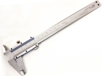

Also, the vernier scale can be different in length. In some models it reaches 2 cm (20 mm) from the main measuring scale, while in others it can be about 4 cm. The longer the length, the more accurately the secondary scale will give readings. Basically, modern calipers are measured with an accuracy of 5 hundredths of a millimeter (0.05 mm), older instruments have an accuracy of only one tenth of a millimeter (0.1 mm), which is half as much.
The caliper has two pairs of jaws: an upper and a lower one. Some have only one, but these are already highly specialized types of devices. The outer width and height are measured with the top pair of jaws. The lower one is measured for the diameter and internal width of the part. The inner grooves must be firmly pressed against the inside of the element so that there is no backlash and the diameter measurement is very accurate.
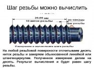
These jaws can move a fairly large distance, so they can be used to measure the diameter, length, width and height of a pipe, a large bearing, large parts and other types of spare parts. But the main advantage of the caliper is that it can determine the parameters of very small or thin objects. For example, they can measure the cross-section of the cable, determine the width of the wire, nail, nut, bolt thread pitch, and much more.
Always during a large amount of turning or plumbing work, they use a caliper because of its convenience and versatility. But this device can also be used at a construction site.

Also, in addition to a pair of sponges, some models also have a depth gauge. It allows you to easily measure depth, even on small parts. This device slides out together with a measuring and vernier scale. The depth gauge line is very thin and fits comfortably at the back of the caliper. In order to measure the depth, simply lower this device all the way into the part (while placing it so that the part itself is supported) and secure from above with a clamping screw. After that, using the measuring scale, you can calculate the depth in the same way as measuring length, height and other quantities.
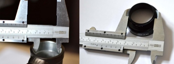
If you don't know which drill you used to make a specific hole, just measure the diameter. In general, a vernier caliper can answer many questions, and after some work with the part to be measured, you can study it completely. An instruction manual may be included with the caliper, so you can familiarize yourself with it before the first work.
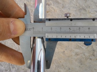

If the vernier caliper is corroded, treat it with a special anti-rust agent. Just make sure that this tool does not corrode the metal, because this can lead to the fact that the divisions and steps on the measuring and vernier scales will not be visible.
There are electronic types of calipers, but they need to be handled more carefully. Avoid contact with water or other liquids in the first place. A short circuit may occur in the electronic scoreboard, and you will not be able to find out the exact data.
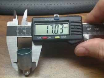
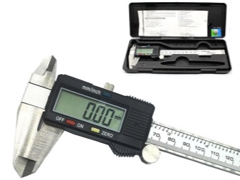
It is also not worth measuring any things powered by electricity. This can knock the scoreboard off and the results after measurement will be incorrect. Before starting work, check the device and press the ON button to turn on the vernier caliper. After you have taken the readings and you need to re-measure, then press the zero position setting button.The principle of switching on is approximately the same as for a non-programmable calculator: after each operation, the value must be reset.
Also, in the electronic version of the caliper, it is necessary to change the power supply. To do this, open the protective cover and replace the battery. Also don't forget about polarity. If the battery is functional, but the display still does not work, then check if the battery is inserted correctly.

Linear measurements
How to measure linear dimensions with a caliper? It all depends on the material of the part / workpiece. For rigid elements, the product is tightly pressed against a base plate, after which the external measuring jaws of the tool are measured. First, you should establish the suitability of the available type of caliper for work. For example, the main measuring scale on the rod should be less than 25 ... 30 mm longer than the part (taking into account the own width of the jaws). When using a depth gauge, this value is even less, since the length of the frame should also be taken into account (for the most common tools 0-150 mm and with an accuracy of 0.05 to 0.1 mm, this parameter is taken at least 50 mm).
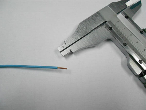
How to measure the wire cross-section with a caliper? Non-metallic products are flexible, and therefore significantly distort the result obtained in the usual way. Therefore, a rigid steel part (screw, nail, piece of bar) should be inserted into the cambric, after which the diameter of the wire section should be determined with external jaws. Do the same if you want to know the internal size of the wire.
Measuring wire diameter
The question of how to measure a chain with a caliper is often asked by cyclists, since the wear of a chain, defined as the distance between its adjacent links, allows a decision to be made to replace the product. The outer jaws are set at a distance of 119 mm and inserted into the link, after which they are stretched to the sides until further increase in size is impossible (to facilitate the work, the chain can be preloaded with a tensile force). Deviation from the original size will show the actual wear, which must then be compared with the maximum allowable.

