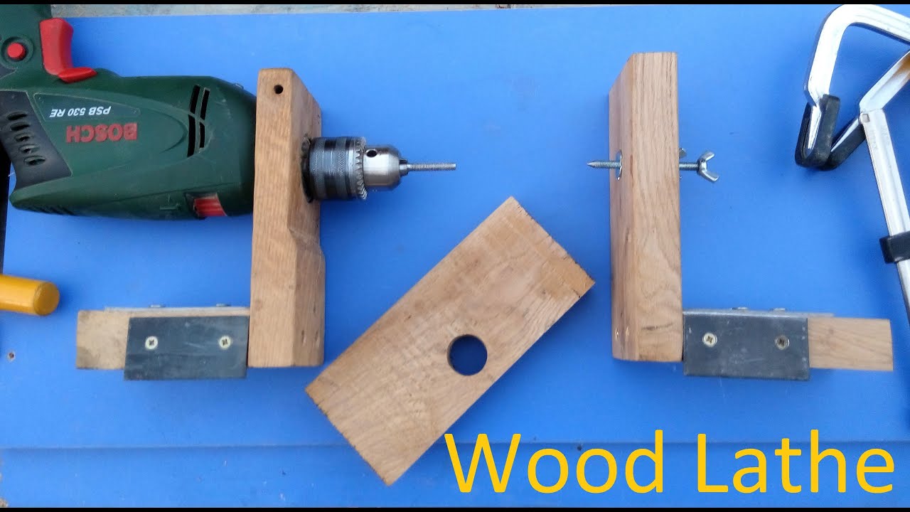
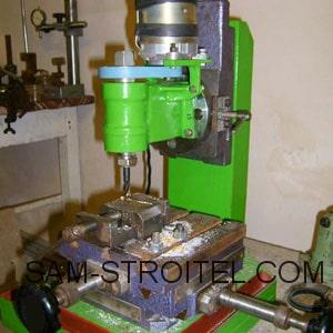
3 DIY drilling machine based on an asynchronous motor
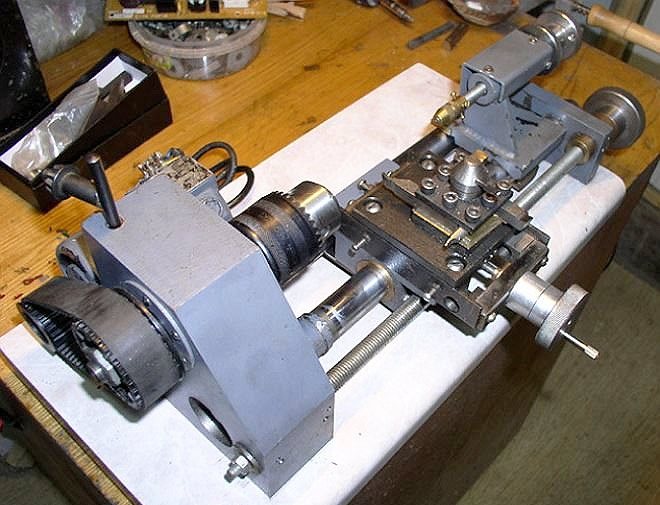
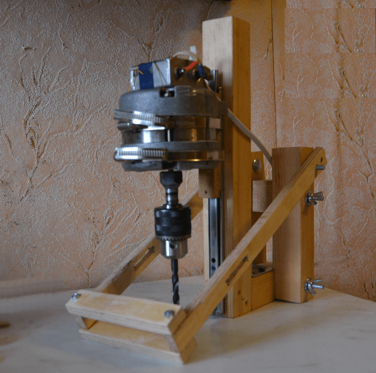
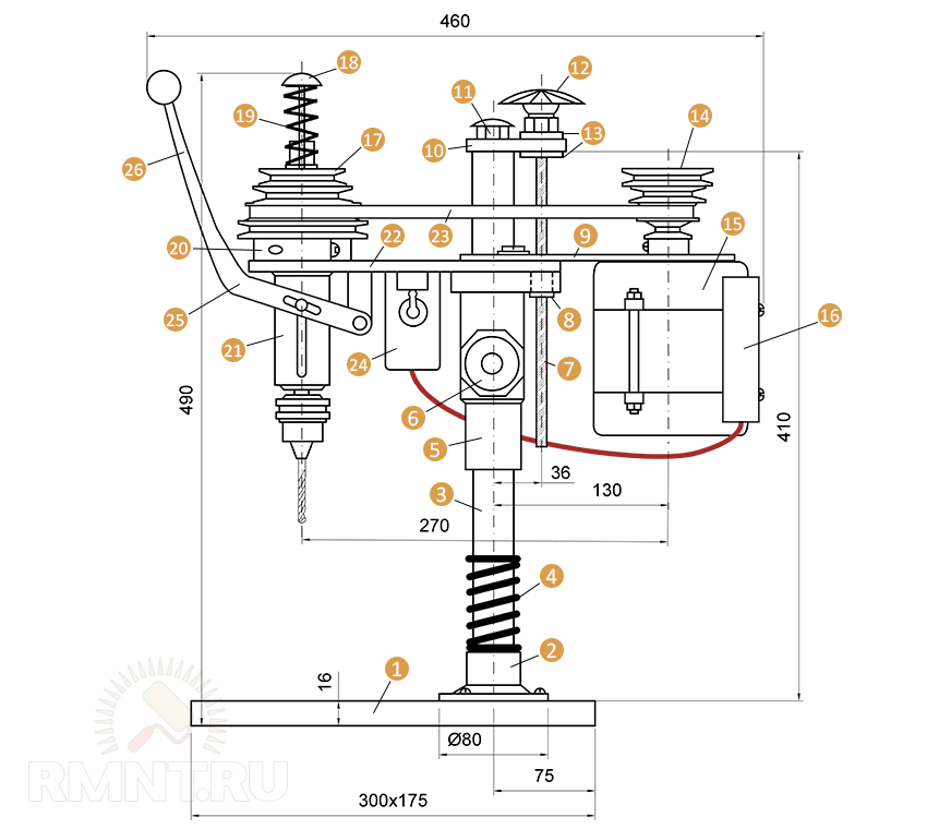
Any owner in the garage, basement or somewhere on the balcony of the apartment has a lot of electric motors from electrical units that have served their time. Of these, it is quite possible to choose a motor that will become a mover for a mini-drilling machine. The ideal option in this case is an asynchronous type motor mounted on drum washing units.
The work of creating a home drilling machine based on an old electric motor is much more difficult than using a drill. But they are quite possible to carry out, armed with a certain amount of patience and perseverance.
It is important to realize here that the motor from the washing machine has a more serious weight. And the power of such a "motor" is much higher than that of an electric drill
This means that you will have to take care of preparing the "mighty" rack and base for the machine being created.
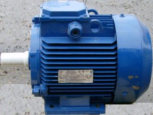
Experts say that it is possible to reduce the vibration level of a unit based on an asynchronous motor by installing it on a strong base, as well as by placing it closer to the vertical rack. But it must be remembered that the close location of the rack and the motor is fraught with the complication of the design of a home-made machine, which is caused by the need to install belt pulleys.
For the manufacture of a drilling machine using an electric motor from a washing machine, among other things, you will need the following parts:
- gear;
- bearings in the amount of two pieces;
- hexagon;
- two tubes of small thickness (one of them must have an internal thread);
- clamping ring (preferably made of strong, e.g. tool steel).
A hexagon is required to make the movable part of the machine tool transfer device. A pulley will be put on it. Also, a metal tube with a bearing and a steel ring must be attached to the hexagon
It is important to achieve a very tight connection of these components to each other, since otherwise, during vibration, they will completely collapse (not immediately, but quickly enough)
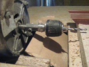
The adjusting complex of the unit is made of a gear and a tube on which cuts need to be made. These include the gear teeth. The specified tube is made of such a height that the drill chuck is lifted by a predetermined amount. An axle with a hexagon is then pressed into the same tube.
It can be seen from the described diagram that it is rather difficult to manufacture a machine with an asynchronous motor. Therefore, it can be advised to do it by analogy with the previous process, when an electric drill was used. But be prepared for the fact that, unfortunately, the resulting machine will not be characterized by special drilling accuracy.
Instructions for creating a stationary circular saw with your own hands
Creating a table for a hand-held circular saw with your own hands is the most important stage in creating a machine, since this structure will host the main parts of the equipment in the form of:
- power unit;
- control block;
- cutting component;
- other components.
The support bed on the hand tool table acts as a guide for the do-it-yourself circular saw. It controls the direction in which the cut is made and fixes the workpiece.

The construction of a table for a hand-held circular saw is the most important stage in the creation of a machine.
Sawmill is a modification of a circular saw. The only difference is that the disc is located at the bottom.The do-it-yourself function of the bed is assigned to the design of the table for a circular saw. A power unit, a block holding a disk and a control system are also installed here.
At the design stage for a circular saw with do-it-yourself drawings, some factors should be taken into account:
The depth to which the material will be cut - the indicator depends on the geometry of the disc.
The power level of the electric motor - a specific indicator of 800 watts will be enough.
Control System Mounting Area - Controls should be located as far from the disc as possible.
Rotational speed - the minimum allowable value is 1600 rpm, otherwise the color will change during the cutting process.

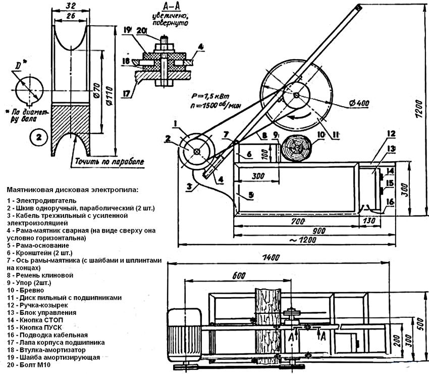
Stationary circular saw device diagram
How to make a circular saw from a grinder with your own hands
First, the table top is made of sheet material. Marking is applied to it in accordance with the dimensions of the instrumentation. Cutouts are made along these markings for installing the saw.
Then it runs:
Installing a parallel stop for a circular saw with your own hands, made from a wooden strip. The element is fixed to the table top.
Stop groove - these elements are formed on the tabletop by milling.
Measuring Ruler Mounting - The mounting area is located at the leading edge of the cutting element. The ruler will be used to control the dimensional parameters of the workpieces.
Installation of clamps is an additional component for fixing the workpiece.
For a machine from a circular saw with your own hands, you will need legs. They are mounted taking into account the dimensions of the table top made of wooden beams with a section of 4x4 cm. The use of steel corners is allowed. To provide additional stability, stiffeners should be installed between the supports. A control unit is placed next to the workplace. You should not refuse to install RCDs and devices that protect the engine from overloads.

A variant of a circular saw from a drill. Layout diagram: 1 - drive (electric drill); 2 - working table (duralumin, sheet s5); 3 - circular saw; 4 - rack (St3, strip 20 × 5, 4 pcs.); 5 - support holder for the mandrel shaft; 6 - mandrel; 7-electric drill holder; 8 - base plate (furniture chipboard, s30)
Homemade machines and accessories for the home workshop: general information
Each owner of a garage or workshop, depending on his needs, selects the equipment himself. Many of them know how home-made machines and accessories for garages are made, therefore they manage on their own when arranging a room, adjusting the technical features of structures for themselves.
So, when creating a metal locksmith workbench with your own hands, the drawings and dimensions of the product on them can be adjusted to the parameters of the room and other conditions. Even a small home workshop will need to set aside enough space to accommodate at least the structure of a universal folding workbench and a minimum set of tools. The required area for this is at least 3-5 m2.

Workshop, equipped in a specially designated room
Manufacturing of tools for storing tools: shelves, racks
In fact, it is very difficult to achieve optimal working conditions. It is desirable that the size of the room be at least 6.5 m. To equip the workshop, you can make an extension to the house or garage. This solution will be the most profitable in any case.
Before you design a drawing of a folding workbench with your own hands, which has the most overall design (therefore, its dimensions are taken into account in the first place), it is worth deciding on some points:
- designate what types of work will be performed in the workshop;
- determine the list of required tools and equipment.
By attaching the tool to the wall, you can significantly save valuable workshop space.Shelves or racks are perfect for this. You can successfully arrange these structures, having achieved the most rational distribution of the area.

The home workshop should be located so that the noise from the working tools does not interfere with the residents
In order to save space, you can get a special device for a circular saw with your own hands, made on the basis of a conventional drill. Such a universal machine can perform several functions at once, combining the following capabilities:
- circular saw;
- grinding machine;
- sharpener;
- mini lathe for wood;
- cutting machine.
The work table can be combined with a joinery bench vise and can be equipped with drawers for storing small tools.
DIY tool shelves: popular designs
Metal structures are more durable and reliable, and wooden ones are affordable. There are several options for the rational storage of tools:
- wall shelves;
- do-it-yourself tool racks;
- suspended ceiling shelves;
- shelves-shields for hanging small tools.

Perforated steel shield shelf for hanging small tools
DIY tool shelf manufacturing technology (shield):
A shield is cut out of a plywood sheet, the places where the shelves will be installed are marked on it.
Using a jigsaw, shelves with side walls are cut out. The length of these sides must match the length of the shield.
Shelves for tools are assembled and fixed on the surface of the shield using long self-tapping screws.
Hooks are being installed. Holes are made in the shield where the dowels are installed. They need to screw in special hooks equipped with threads. Previously, it is worth distributing the entire tool and marking the points where it will hang.
Brackets or lugs are mounted on the rear wall of the structure.
It remains only to fix the shelf-shield on the wall. To prevent the lugs from sliding off the anchors, it is recommended to fix them with special washers.

Diagram of the device with the mounting dimensions of the tool rack in the workshop
Features of the use of machines
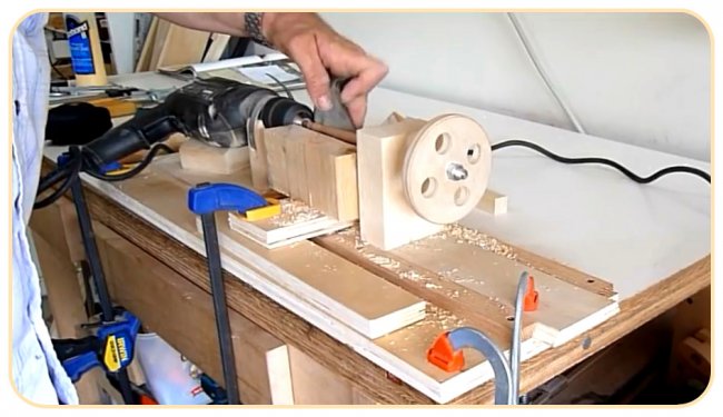
Working with a drill while holding the tool with only hands significantly limits its capabilities. The weight of the tool and vibration do not allow the drill to be rigidly fixed in the desired position. But if you think over and design a special bed, where it will be stably attached, then an ordinary hand drill will turn into a professional, almost industrial equipment.
You can independently make the following types of machines from a drill:
- drilling;
- turning;
- milling;
- grinding.
Moreover, after replacing the working or cutting element, the machines become interchangeable. Provide two-in-one function, such as drilling and milling machine, lathe and grinding. It all depends on the installation conditions and the needs of the owner.
The power of the machines and their capabilities will depend on the type of drill (the power of its electric motor), the method of fastening, since it is in this case that it acts as the main working part of the equipment.
Other functional details
Their list is as follows:
- Base plate. It dampens elastic waves.
- Drive board for vibration damping.
- Comb stops (combs). Needed to neutralize vertical vibrations of the workpiece.
- Static side stop. Ensures the correct feed of the workpiece and the depth of its horizontal processing.
- Dust catcher.
Drive unit
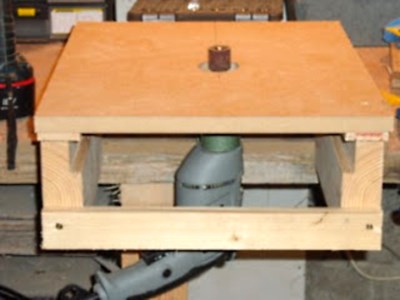
It is better to make the opening for placing the drive round, so the machine will have less vibration during operation. The motor must not come into contact with the plate.
The installation of the drive in this plate is as follows:

It is better to create a drive board from PCB or fiberglass with a density of at least 1.5 cm.
Thick plywood (1.9 cm), treated with vibration-absorbing agent, is used for the slab.
The board and the plate are separated by a gap of 0.5 - 1mm.It is desirable to have mounting feet on the engine, and they should go beyond the body. This will allow the cutter to move upward. Long motor bolts are used to mount it. The removal of the cutter is ensured as follows: between the engine housing and the suspension pillow, steel washers with rubber gaskets are put on the bolts in turn.
Emphasis
A suitable material for the stop is thick plywood (from 2 cm). It is required to drill 3-5 holes for combs and risers. The first two are 5 mm from the outer edges of the cutter cut. Others - after 2.5-3 cm. The positions of the stops depend on the parameters and quality of the workpiece.
The side stop diagram is as follows:
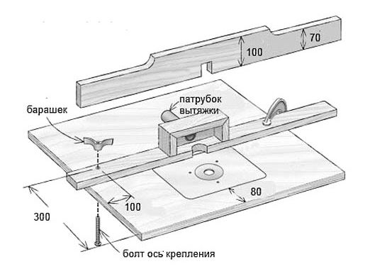
It can be configured like this:

System elements
- Bucket for 15-20 liters. With a tight lid and snap-on latches.
- Branch pipe 1 - inlet. Diameter - 2 cm. Its end is beveled 45 degrees and rotated 25 degrees outward. It is placed 2 cm from the side of the container.
- Branch pipe-2 - exhaust. Diameter - 3 cm. Placed strictly vertically on the bucket. Its selective ending is narrowed to 1.5-2 cm.
- Vacuum cleaner.
Combs
For combs, oak or walnut is used, without fungi and defects. They are made on the right and left sides for easy feeding of the workpiece.
Drawing:
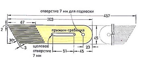
The length of the first tooth is reduced by 3 mm. The reason is that it acts as a rebound spring for the whole ridge. Without this, a breakdown may occur.
The combs are attached to the stop with a special bolt through a slotted hole.
The non-working element is fixed with a self-tapping screw to the same stop through hole D7.
For operation, the comb is placed so that it contacts the workpiece with all teeth, except for the initial one. Then it is secured with a lamb.
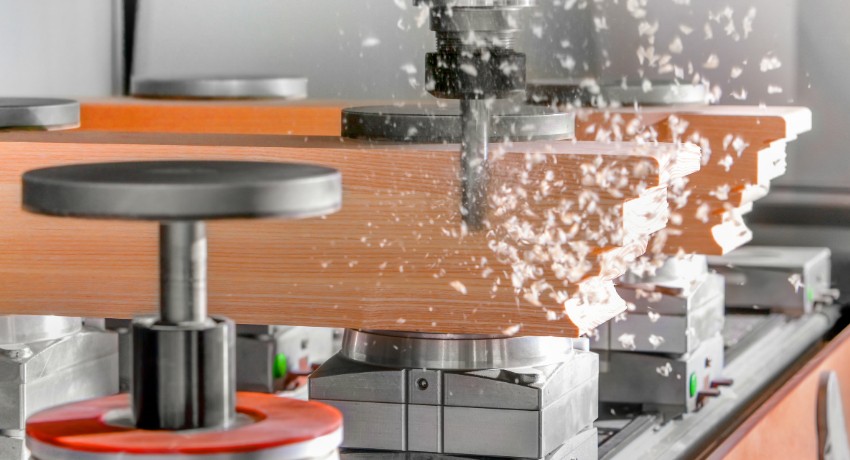
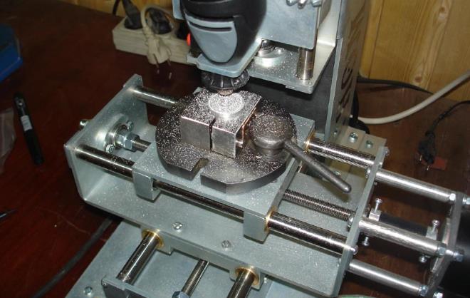
Features of do-it-yourself CNC milling machines
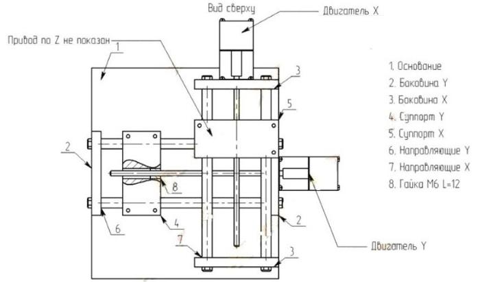
Software is considered to be an important component in a do-it-yourself CNC wood router. Drawings of a conventional design, taking into account this condition, must include additional elements for it:
- LPT port;
- CNC unit.
Assembling a wood router for a home workshop
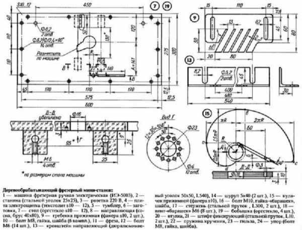
At the first stage, do-it-yourself drawings are drawn up for a wood milling machine, which include information on the placement of all structural components, their dimensions, as well as methods of fixing.

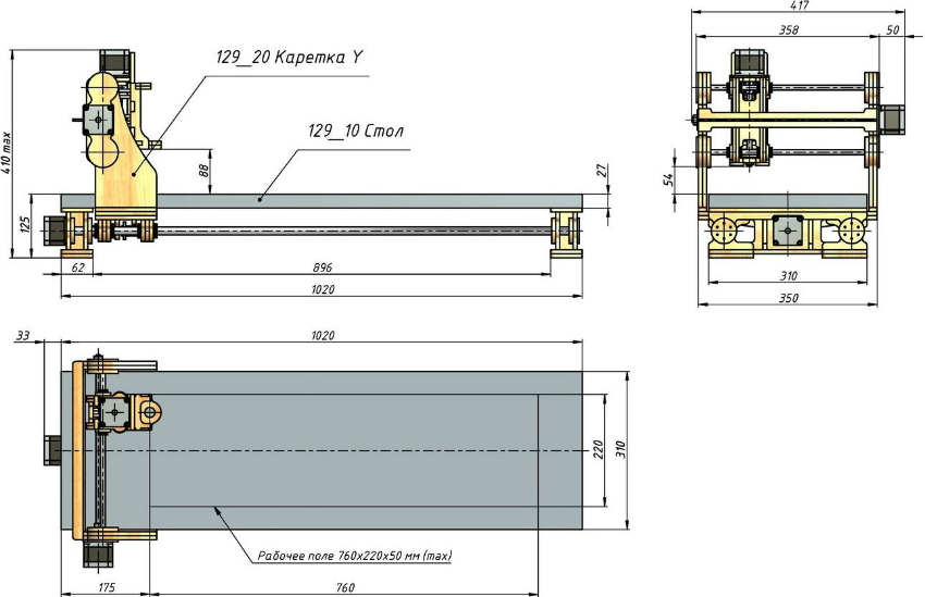
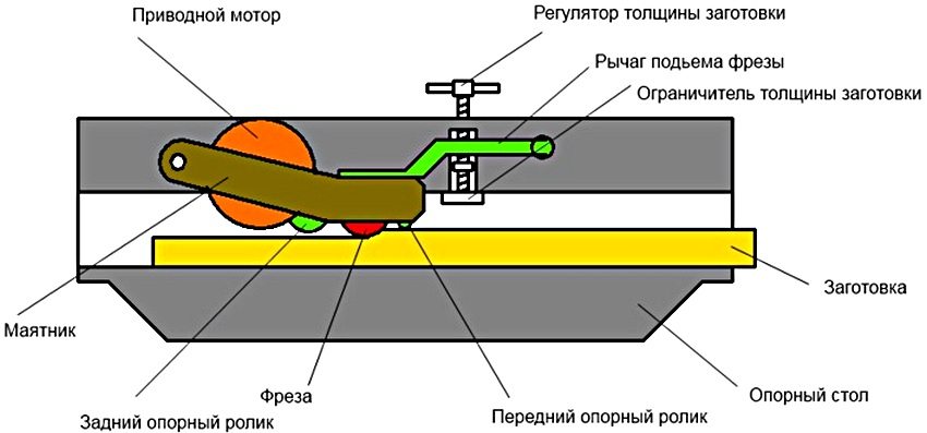
Diagram of a CNC milling machine
Next, a support frame is assembled from pipes pre-cut into parts of the required size. For fastening, you need to use a welding machine. Then the dimensional parameters are checked in order to start manufacturing the working surface.
You need to act within the framework of the following scheme:
Marking is applied to the fiberboard plate and a tabletop is cut out of it.
If the cutter will be placed vertically, a cutout must be made for it in the slab.
The spindle and electric motor are being installed. In this case, the spindle should not go beyond the plane of the working surface.
The limit bar is installed.
Be sure to test the machine before work. When the router is switched on, it should not vibrate too much. To compensate for this disadvantage, it is recommended to additionally install stiffeners.

The most important requirement for workshop machines is operational safety.
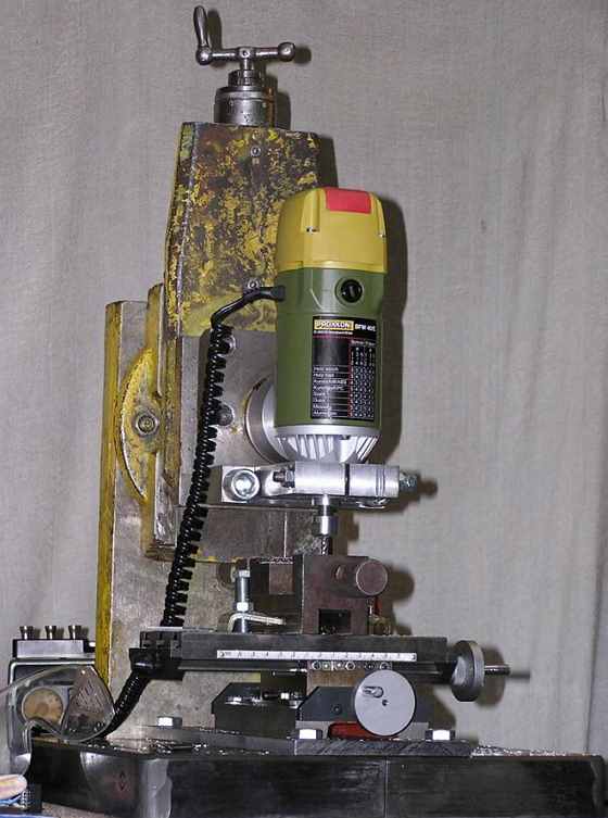
DIY metal milling machine assembly
Step-by-step instructions for making a homemade metal milling machine:
Column and bed made of metal channel... The result should be a U-shaped structure, where the base of the tool acts as the lower cross member.
Guides are made from the corner. The material must be sanded and bolted to the column.
The rails for the console are made from the square section tube. Here you need to insert pins with a screwed thread. The console will be moved by a diamond-shaped car jack to a height of 10 cm.In this case, the possibilities of the amplitude to the side are 13 cm, and the table top can move within 9 cm.
The work surface is cut from a plywood sheet and screwed in place. The fastener heads must be recessed.
On the working surface, a vice is mounted, made of a square tube and a metal corner, welded together. It is better to use a threaded pin as an element fixing the workpiece.

Diagram of the device of a milling machine (a - general view, b - kinematic diagram): 1, 5 - ruler guides; 2 - toothed sector; 3 - cutter; 4 - fence; 6 - control panel; 7 - additional support for the spindle; 8 - bracket; 9 - arm lifting handwheel; 10 - belt tension handwheel; 11 - electric motor; 12 - spindle; 13 - handwheel for adjusting the spindle height; 14 - bed; 15 - spindle speed switch; 16 - switch; 17 - table
After that, you need to attach a cone (Morse 2) to the spindle and install a collet or drill chuck on it.
Make or buy?
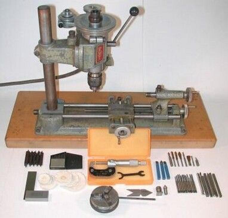
An electric drill is a ready-made drive, transmission, spindle and chuck in a monoblock. Put it on the carriage of the machine - and you can drill. In terms of accuracy, the solution, generally speaking, is not optimal (see below), but in many cases acceptable, but eliminates the need to order expensive turned parts of increased accuracy, see below. In view of what, drill stands are now sold, perhaps not on the street from trays; prices are affordable. Choosing one to make a drilling machine from a drill, be guided primarily by the operating mode of the equipment; the price also depends on it:
- Occasional drilling / milling for yourself with the accuracy that will turn out - the bed is plastic cast or steel stamped. Lever feed mechanism with bell crank (see below). Sliding bearings of the carriage (see below) steel on steel or with nylon bushings. Prices are $ 20- $ 30.
- Regular drilling for yourself or to order with conventional machine-building precision. Workable materials - up to the hardness and toughness of conventional structural steel. All the same, but the plain bearings are steel on steel (worse) or with bronze bushings, and the frame is cast iron or (more expensive) composite, also vibration-absorbing. Prices are $ 30- $ 40.
- Regular drilling and milling of any material amenable to the tool with periodic tool overloads and / or with increased accuracy - plain bearings only bronze on steel, cast iron bed. Rack and pinion feed mechanism (see further below); vibration-absorbing console. Prices are $ 60- $ 180.
Choosing a bed
The drill stand (which for some reason the sellers stubbornly call it stands) must be chosen not by manufacturer ("china" - not "china"); now the market is full of "German China", not to mention the products of the post-Soviet states. We need to check the design.
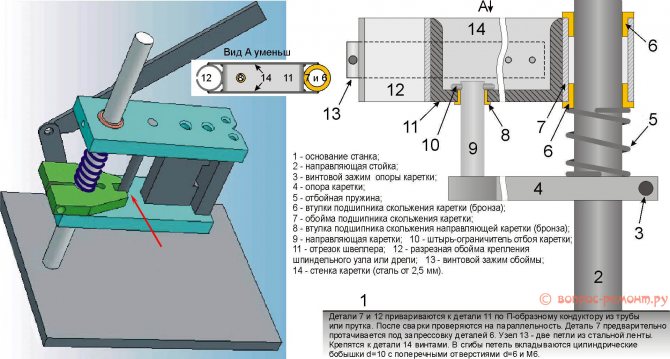
First, samples with plastic non-nylon plain bearing shells are unambiguously rejected: runout and drift of the drill by more than 0.5 mm will appear already at the 10th - 20th "hole" and will increase further. The second is the backlash of the console. We take it by the far end, swing it up and down and to the sides with the clamp clamped. Noticeable "talkers" shouldn't be (the tactile sense of an untrained person feels a beat of 0.4-0.5 mm).
Further - inspection of the structure, see fig. below. For conventional drilling, the one shown in pos. 1. The ideal option is at pos. 2: drill collet, lateral displacement of the column reduces the vibration of the console by an order of magnitude, and by turning it sideways by 45 degrees, you can milling by hand with accuracy "as you can" a part on a standard non-sliding table, removing a couple of table mounts, since in this case, its manual displacement relative to the horizontal working axis of the console will be linear.
How to choose a drill stand (stand)
And here is a sample in pos. 3 do not take in any case.First, the collar of his column is low and its fastening is unreliable. Secondly, the longitudinal grooves under the table facilitate manual milling "as it happens", but, unlike the diagonal ones, they do not dampen the vibration of the bed. Moreover, they will concentrate where indicated by the arrows (the tide under the column is made too narrow) and from there they will go straight to the column and table.
Which is cheaper?
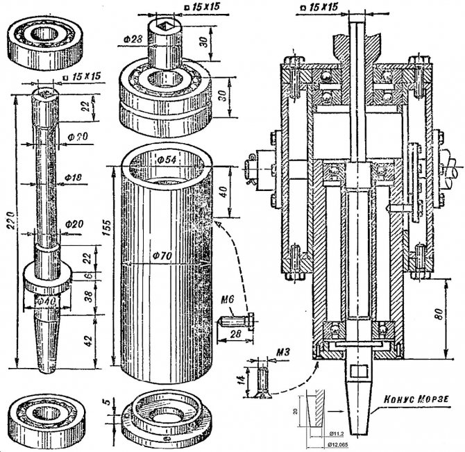
Desktop Drilling Machine Spindle Drawings
Let's say the price of the frame you like doesn't suit you. Or a drill, if "crowbar", with a percussion mechanism, which was in the work on building structures and the beating of the cartridge is visible by eye. Then, first of all, we find out if a master who owns a high-precision lathe (no rougher than 0.02 mm) is within reach. Which, by the way, is not a fact - a high-precision machine is very expensive and never pays off in the flow of common orders. But, suppose, I found it. We take the drawing in fig. on the right, we go to him and ask if he can carve it out of steel no worse than 30HGSA, and how much he will take for the work. "This" - the drawings of the spindle of the bench drill. The rest of its parts can be carved on an ordinary machine, or found in the ruins of the iron bazaar or in your trash. Most likely, it will turn out that buying a bed + a table is cheaper, and if you estimate the costs for the rest, then, perhaps, a drill of increased accuracy will be outlined. On sale there are such; they can be recognized by the absence of an impact mechanism and a collar specifically for installation in the bed: it is wearing a turned steel cuff.
Drive implementation
Many craftsmen and DIYers are often interested not even in how to make a lathe for wood, but in which drive to choose.
Here, of course, it all depends on your capabilities, as well as on what exactly you are going to do, what details to grind.
If we are talking about a budget option, for which drawings and serious calculations are not required, then an electric drill will quite cope with the role of a drive. This is one of the most commonly used options.

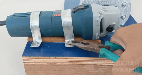
Some craftsmen use an angle grinder (grinder) instead of a conventional drive from an electric drill, but such a constructive solution has not been widely used.
Moreover, the use of a grinder without adjusting the speed is generally impractical. Read more about making a lathe from angle grinders in our article.
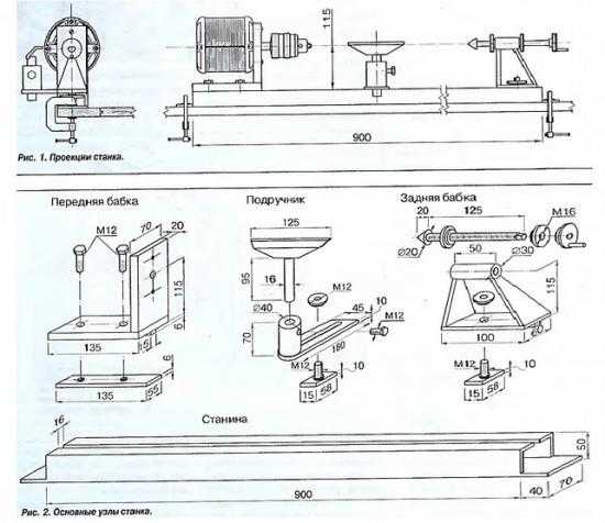
If you need a structure in order to make different crafts and parts from wood, then it makes sense to use an electric motor, which will be connected to the drive pulleys by means of a belt (and they must be of different diameters).
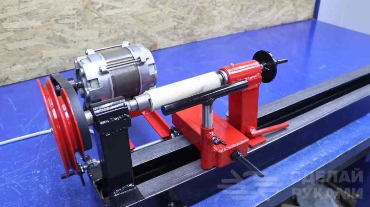
At the same time, the lathe itself, or rather its main elements, it is desirable to make of metal
In this case, the design will turn out to be not only reliable and solid, but also safe, which is also important.
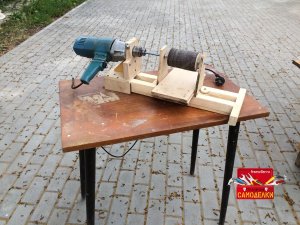
Using a drill
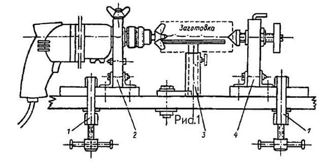
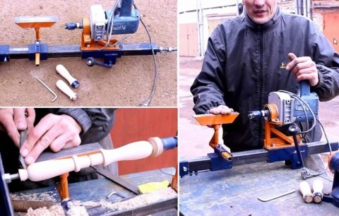
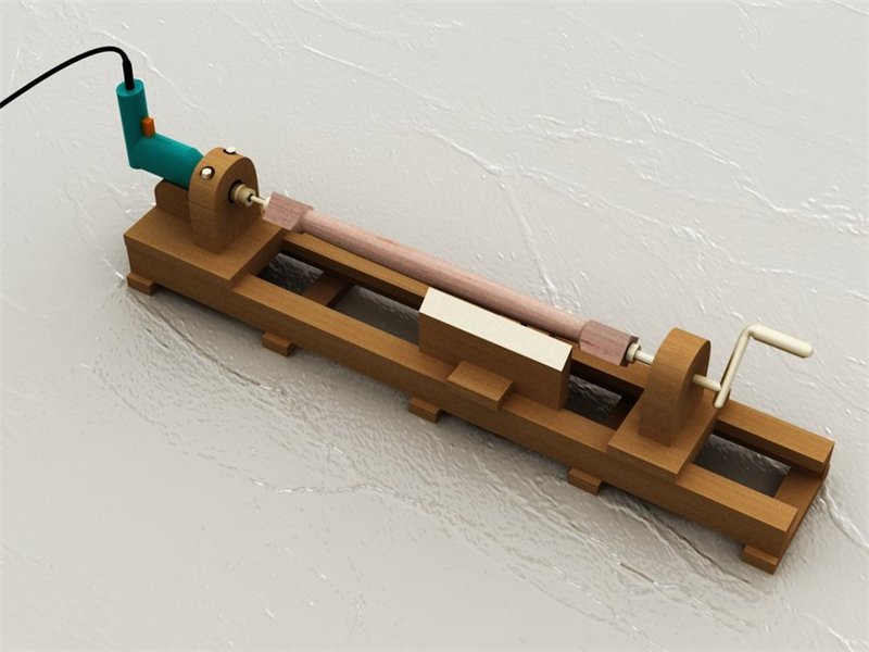
As it was written earlier, one of the most popular designs for a garage and a home workshop is the simplest lathe based on an electric drill.
It is not difficult to make it, but to work on it is simple. For the manufacture of basic structural elements, you can use what you find at your fingertips.

For example, a frame can be made from a piece of metal I-beam. You can also take a channel or a building corner as a basis - there are a lot of options.
The grandmas themselves can be made from the same I-beam. You will also need to make a simple clamp to securely firmly fix the electric drill in place.

Such a mini wood lathe can be installed directly on the desktop, and after finishing the work, it can be removed to the corner of the workshop by removing the drill from it.
With a washing machine motor
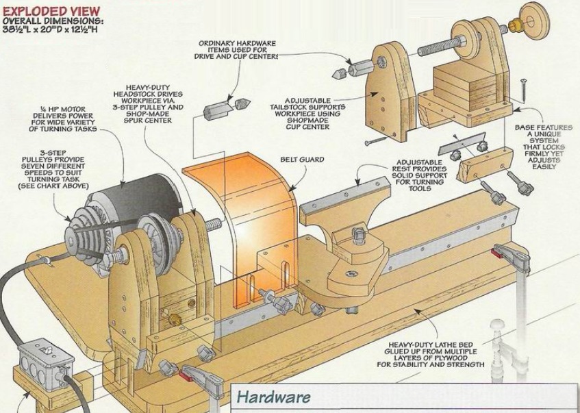
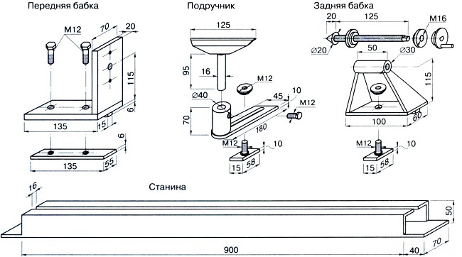
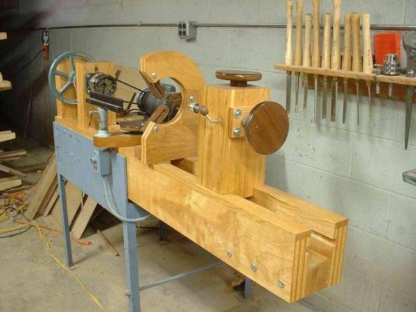
If designs based on a power drill are popular due to their ease of assembly, then machines driven by an electric motor attract attention for their versatility.For the manufacture of such a lathe, you can already separately develop drawings with the main components and detailed dimensions.
This will help a lot when building
For the manufacture of such a lathe, you can already separately develop drawings with the main components and detailed dimensions. This will help a lot when assembling.
Please note that when using a motor from a washing machine, several basic design solutions can be used.

It is possible to implement both a direct drive, when a special (often self-made) attachment is put on the shaft to fix the workpiece, and indirect drive, when the rotation to the spindle is transmitted through a system of pulleys and a belt drive.
The tailstock is attached to a movable platform, which makes it easy to move it along the bed, adjusting to the size of the workpiece or workpiece.
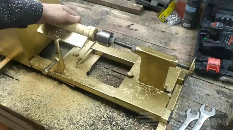
Be sure to make a case of metal or wood, inside which there will be an electric motor.
And on the front side of the case, you can bring the power button. Additionally, if possible, you can install a speed control board.
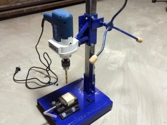
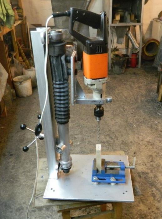
2 How to make a drilling machine from a drill?
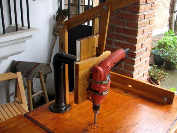
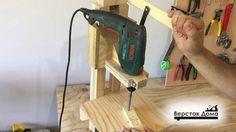
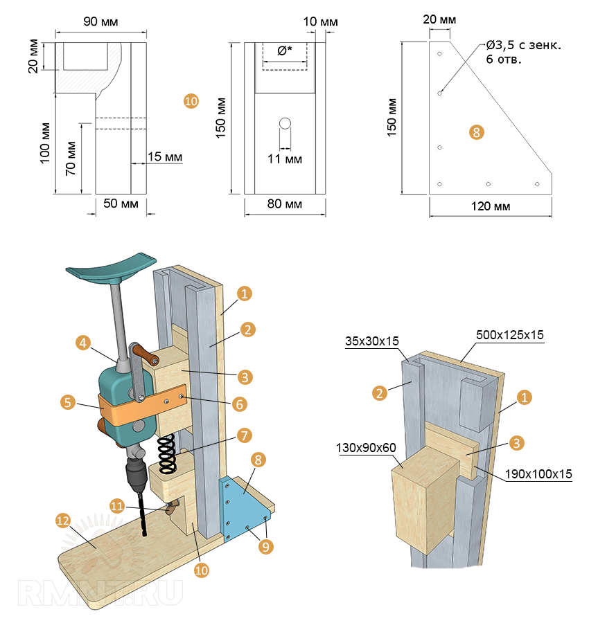
In home workshops, such drilling equipment is most often found, due to the simplicity of its independent manufacture. You do not need high strength materials or any special fixtures. The Mini Hole Drilling Machine contains only four key components:
- bed, which serves as the base of the machine;
- rotation mechanism (in our case, an electric drill plays its role);
- feeder;
- vertical rack.
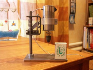
The stand is usually made from ordinary chipboard or from boards, since the small mass of the drill does not require the use of more durable materials. But it is better to make the frame as massive as possible. This will ensure that there is no vibration during the drilling process, which means more comfortable work.
Masters advise using a relatively thick (from 2 centimeters) furniture board for the base of the unit. The ideal option is the use of an old photo enlarger for the manufacture of the bed and rack. It will only need to be slightly modified to get a truly reliable design for a mini-machine for domestic use.
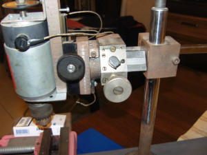
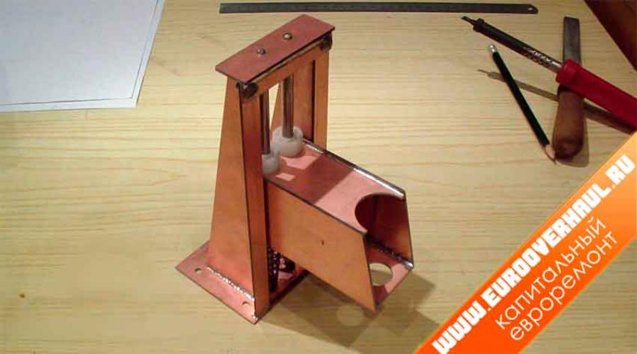
The quality and accuracy of drilling on a homemade unit depends on the correct connection of the bed and the vertical rack. Therefore, this part of the work must be approached as responsibly as possible. It is recommended to cut two rails out of the steel strips, which are then screwed onto the rack. The block with the drill will move along the indicated guides.
The block itself must be made so that it reliably holds the electric drill. This is easy to achieve using small steel clamps. It is also advisable to place a small rubber pad between the shoe and the drill. It will significantly reduce vibration and make the operation of the unit more comfortable.
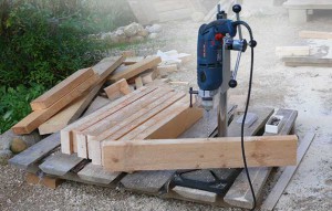
The feed mechanism of the drilling machine from the drill is the simplest lever that will move the block with the tool in the vertical direction. It is desirable to provide this mechanism with a spring of relatively high elasticity and power. One end of the spring should rest against a fixed wooden bar mounted on a rack, the other against a block.
If you want to achieve the maximum convenience of working with a home-made machine and do not plan to periodically remove the electric drill, it is recommended to simply disassemble its switch, and mount a separate button on the bed, with which you will start and stop your drilling unit. As you can see, everything is pretty simple. Any more or less "handy" man is able to make himself a small and convenient machine out of a drill.
Manufacturing algorithm
Considering that by the type of processing, home machines will be interchangeable, and the nozzle installed in the drill will play a decisive role, we will consider two main options for homemade units - horizontal and vertical.
The assembly procedure for a vertical machine is as follows.
- Cut a 50 x 50 cm square base from a piece of metal or wood, 10 to 20 mm thick.
- Exactly in the center at a distance of 1-2 cm from the edge, drill a hole in it for mounting the rack. The diameter of the rack must be at least 5 cm.
- Install the stand, center it with a level and weld with a welding electrode. If a wooden machine is made and the rack is wooden, then rigidly fix it with self-tapping screws.
- Fix the drill with metal clamps on the movable element, which will be put on the rack, forming a lowering / raising spindle.
Put the spring on the rack. Its length should be at least 2/3 of the rack.
After placing the drill on the stand, mark the place where the drill will fall when lowering the spindle.
According to this place, cut two through hollows in the bed crosswise.
A table is installed in the hollow on a threaded pin, on which the workpiece will be attached. A nut is screwed onto the pin from the bottom side, it will fix the table in the desired position
From the outside, you can also attach the table to the pin with a nut, sinking it into the surface of the table so that it does not interfere with the stacking of the workpieces.
It is important that after locking with the nut, the length of the outer part of the pin is flush with the top of the stage.
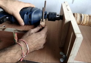
The assembly algorithm for a horizontal machine looks like this.
- Cut a rectangular bed - dimensions are determined individually.
- On one edge, fix the seat for the drill with a hollow in the upper part corresponding to the size of the tool.
- Fix the drill on it with a clamp.
- Cut a through groove for the pin along the bed, and install two metal corners along the edges, along which the pressure sleeve will move.
- The width of the clamping sleeve must exactly match the distance between the guide angles (runners). From below, a threaded pin is screwed into it, which will move in the hollow.
- Having moved the sleeve close to the drill chuck, determine the place where a special headstock will be installed for fixing the workpieces.
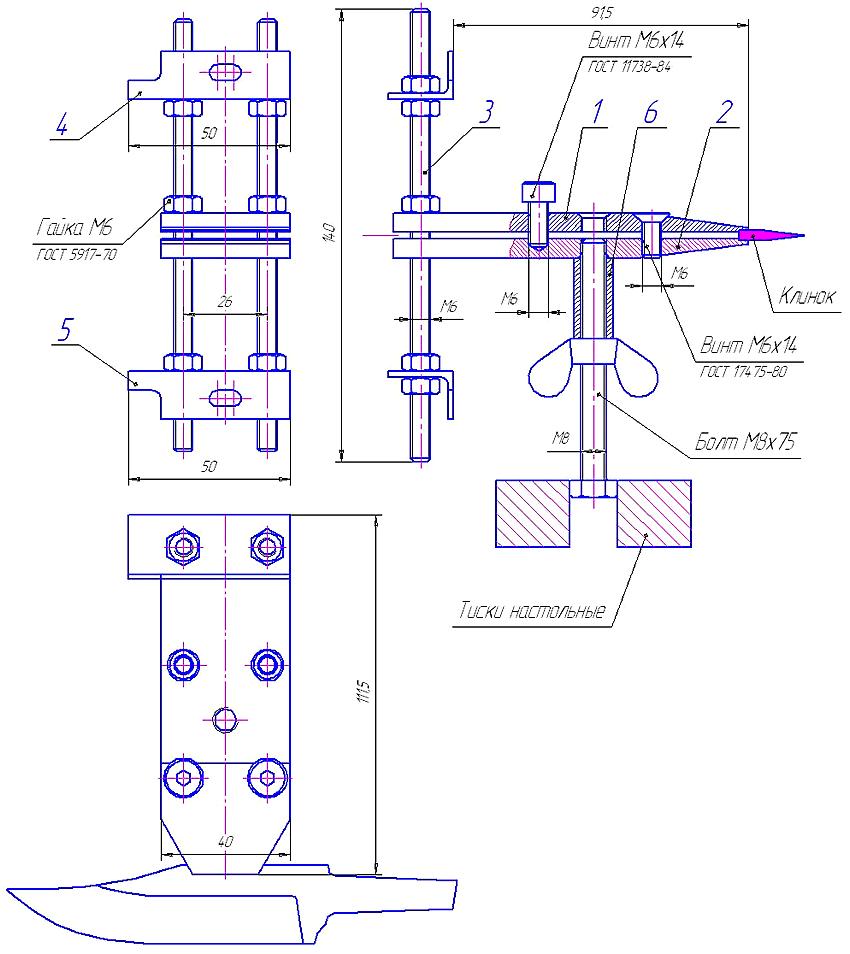
- Attach a headstock with a centrally positioned metal tapered pin to the bushing.
- The sleeve is fixed in the desired position (for clamping the workpiece) with a nut screwed onto the pin from below.
In both versions, it is necessary to provide special adjustable legs for the bed.
If the bed lies flat on a workbench or table, it will become impossible to adjust and fix the clamping sleeve on a horizontal machine or a table for workpieces on a vertical one.


