Measurement and marking of workpieces with a height gauge
Let's talk about how workpieces are measured and marked when using a manual height gauge.
Measurements
Take measurements with a manual height gauge in this order.
-
Slide the foot holder onto the protrusion of the device frame.
-
Place the foot in the groove in the holder. Secure it with the set screw.
-
Place the height gauge on the control reference plate.
-
Make sure the appliance is level.
-
Holding the base of the tool with your left hand, move the frame up and fix the leg above the workpiece.
-
Place the product under the foot of the height gauge.
-
Lower the frame until the foot is firmly in contact with the upper surface of the workpiece.
-
Fix the position of the frame with another set screw.
-
Take the readings.
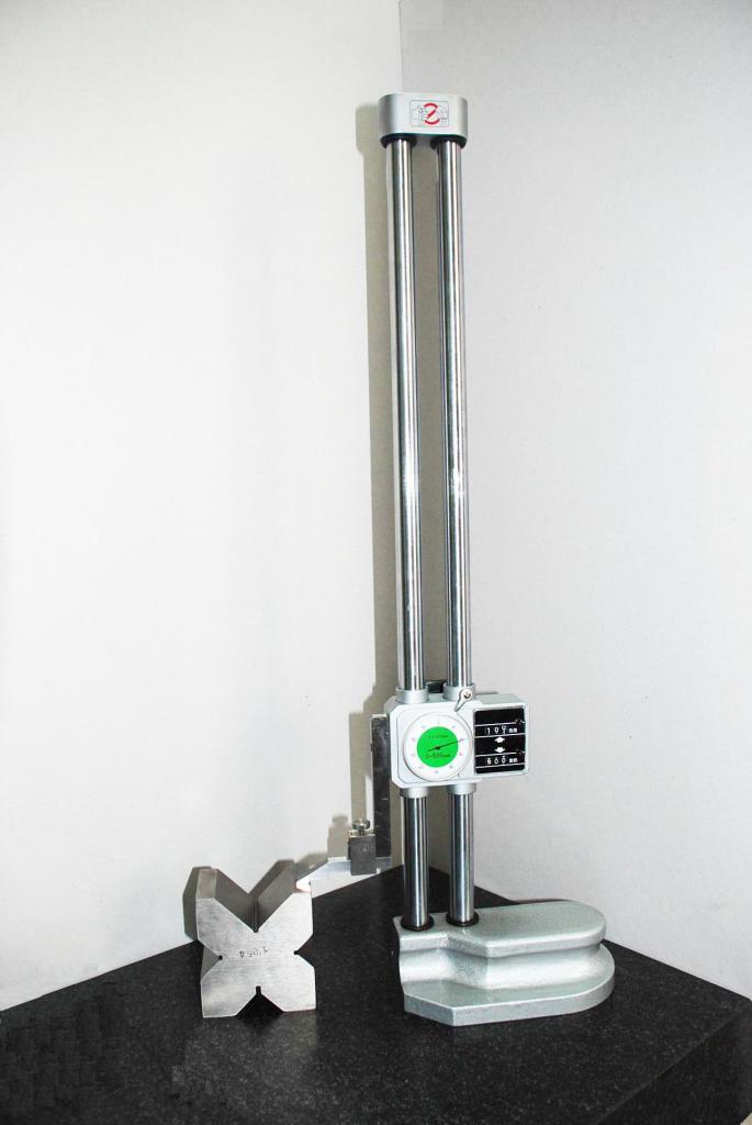
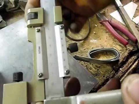
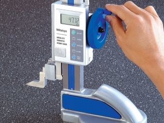
Photo # 2: measuring the height of the product with a height gauge
Markup
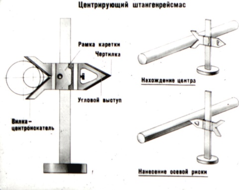
Most often, using height gauges, lines parallel to the horizontal reference plate are applied to the workpieces. For this:
-
set the frame to the desired height (you can estimate the correctness by the values on the instrument scales);
-
fix the frame with the locking screw;
-
place a scribe with a carbide tip in the slot of the holder;
-
secure it securely with the locking screw;
-
set the marking gauge and the workpiece on the measuring plate (the scribe should touch the product with effort);
-
to obtain a horizontal line, move the appliance over the plate while holding the base.
As a result, a clearly visible line will appear on the surface of the workpiece at the desired height.
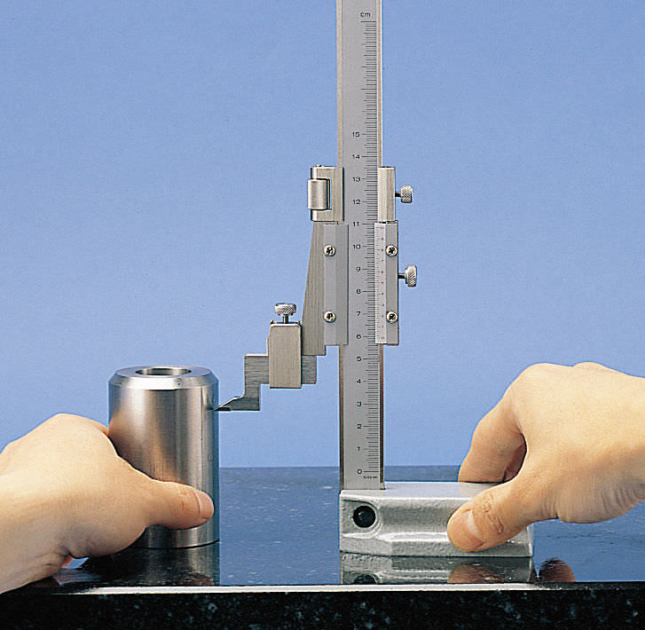
Photo # 3: marking the workpiece with a height gauge
Checking the instrument
The method of calibrating the height gauge provides the following. First, check the setting zero of the tool used. For this, the device is placed on a reference plate and moved in the longitudinal direction. The control line should not have broken sections and other deviations that, in absolute terms, are outside the accuracy limits. The digital height gauge is verified in the same way, only the indicators of the digital display are monitored.
The purpose of the height gauge - accurate drawing of dimensional lines and making measurements - can be fully realized if the following rules and requirements are observed:
- Significant fluctuations in temperature and humidity during operation are unacceptable. In particular, the normalized temperature range is 20 ± 10 ° C, and the relative humidity is 70 ± 5%.
- If the diameter or configuration of the measuring head is changed, the verification must be performed again.
- Verification is always performed several times (at least three), after which the vernier readings are compared for the vernier height gauge. The digital instrument is verified by the deviation of the readings of the included display screen.
To check the results obtained, a reference micrometer is used, the accuracy of which should not be lower than the accuracy of the verified technique.
How it works and functions
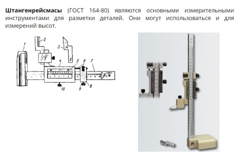
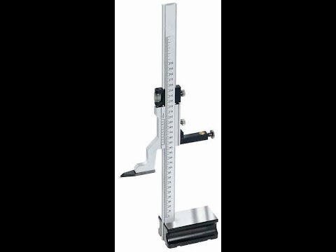
GOST 164-90 provides for the following standard device of a height gauge:
- base;
- yardstick;
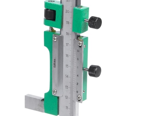
- vernier (scale for counting additional readings in fractions of mm);
- micrometric feed frame;
- holder for fastening replaceable tips;
- counting prism (or scribe, depending on the actions with the instrument).
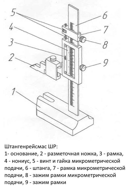
Device and main details
In accordance with the methodology, which is prescribed in GOST 164-90, the tool in the marking mode should be used as follows.All measurements should be carried out on a solid and level slab with a minimum surface roughness. A base is installed on this plate, after which, using a frame and a vernier, the required linear dimension is set, which must be reproduced on the surface of the workpiece or semi-finished product. A scribe is placed in the holder, which is rigidly fixed with a micrometer screw. The frame, which is previously locked with a screw, is pressed together with the body to the surface to be marked. Next, the tool is moved to the required linear dimension, while the scribe tip should leave a visible mark on the surface of the workpiece.
The height gauge, the purpose of which is measurement, instead of a scribe in the holder has a prismatic or conical pointer, which ends with a small radius head (according to the current standards, this can be 50 or 100 microns).
Classification
In accordance with the specified standard, the GOST 164-90 height gauge tool in question can be classified according to the following parameters:
- By the way of reading off - manual with linear reading, manual with circular reading and automated (digital).
-
By the limiting length of the measured product (for hand-held devices), which is indicated in the designation. According to the 1st row of preferred numbers, the manual height gauge GOST 164-90 of the ShR type with a linear readout of readings can be of the following types: the height gauge ShR-250, the height gauge ShR-400, the height gauge ShR-630, and so on, up to the ShR-2500.
- Accuracy class. In particular, according to GOST 164-90, the first class corresponds to an accuracy of 0.05 mm, and the second to 0.10 mm. Accuracy decreases with increasing limits of the measuring range. For example, if only the upper limit of accuracy is required for the ShR-250 type, then the ShR-630 GOST 164-90 height gauge can have an accuracy of 100 microns. For the least accurate instruments, the accuracy is correspondingly reduced to 150 ... 200 µm.
- Along the length of the scale. For instruments of the 1st class, it can be 19 and 39 mm, and for the 2nd - 9, 19 and 39 mm.
- The electronic height gauge additionally differs in the display resolution step: 0.03 ... 0.07 mm for the 1st accuracy class and 0.05 ... 0.09 mm for the 2nd accuracy class.
The standard designation of the instrument in question includes all of the above factors. For example, a hand tool with a reading range of 60-630 and a reading accuracy of 0.10 is designated as follows: ShR-630-0.10 height gauge GOST 164-90.
Appointment.
1.1. Shtangenreismas ShR is designed for marking work, drawing marks, transferring dimensions from a scale ruler to a workpiece, measuring linear dimensions (heights). It is used to draw parallel horizontal and vertical lines on the parts installed on the plate, as well as to check the correct installation of products. The tool consists of a frame with a vernier with a hardened measuring surface and a rod with a measuring surface. The frame is supplied with a vernier. The rod is made with a recessed scale, which eliminates the wear of the scale when moving the rod in the frame. The boom and vernier scales have a matt chrome finish to eliminate glare. It is used for measurements that do not require high accuracy, using the absolute method.
1.2. An example of a standard designation of a height gauge with a measuring range of 0-200 mm and a vernier reading of 0.05 mm:
Shtangenreismas ShR-200-0.05.
Electronic (digital) height gages
Most widespread today due to simplicity
use and the highest accuracy received electronic (digital)
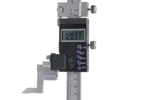
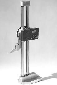
ShRTs height gauges. Consider the capabilities of this type of device using an example
height gauge Mahr.
The tool is equipped with an ABS function for
switching between relative and absolute measurement (for
To facilitate the use of the first mode, the device has a Reset function to zero the readings, and Preset to preset values). Maximum speed
measurement is 1.5 m / s, the device has a fine-tuning function.
Reference-Lock / Unlock functions allow you to lock
and remove the readings fixation. The data transfer mode is activated by the DATA button. Automatic shutdown of the device after
the expiration of the set waiting time significantly saves the power supply
nutrition.
Battery life is approaching instrument life
and is about 3 years old. Measurement information is displayed on the LCD display,
the height of the numbers is 1.2 cm.
The frame of the height gauge and its rod are made of
stainless steel for smooth sliding of the moving surface.
Published on 03/28/13.
Device
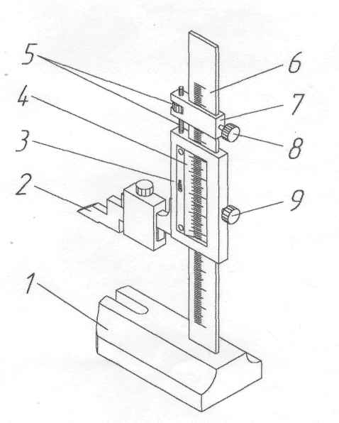
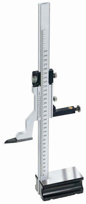
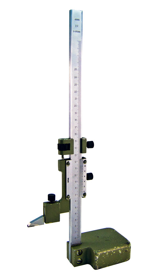
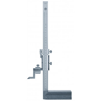
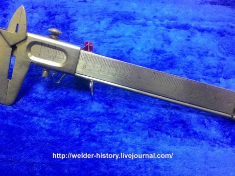
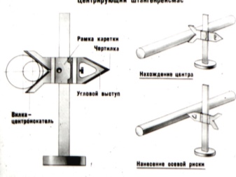
The construction of a conventional height gauge is quite simple. Its main parts are:
- massive base;
- a vertical bar on which a millimeter basic scale is applied (sometimes it is called a ruler, since in appearance it resembles this very instrument known from school years);
- main frame;
- vernier (additional micrometric scale on the main frame);
- measuring leg.
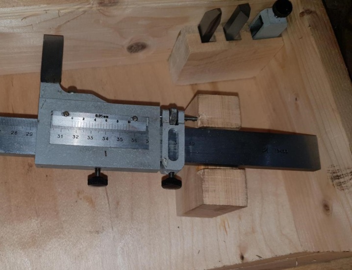
All other parts are auxiliary: fasteners, adjustments. It:
- screw and nut for moving the main frame;
- micrometric feed frame;
- frame fixing screws;
- holder for replaceable tips of the measuring leg;
- scriber.
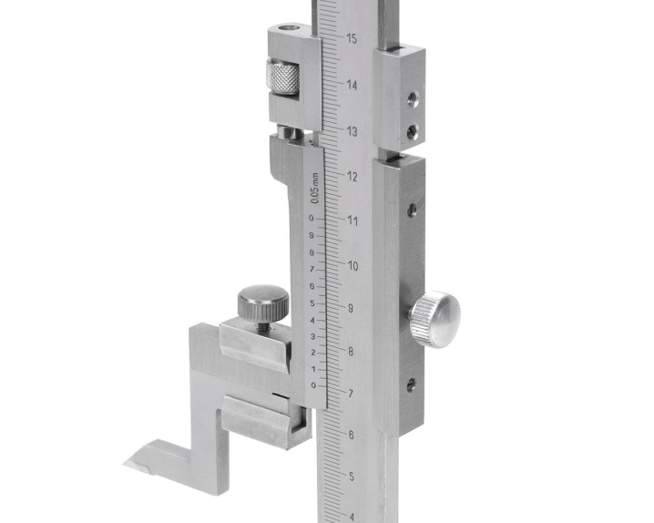
The rod with the main measuring scale is pressed into the base of the tool strictly at a right angle (perpendicular) to its reference plane. The rod has a moving frame with a vernier scale and a projection to the side. The protrusion is equipped with a holder with a screw, where a measuring or marking foot is attached, depending on the forthcoming operation: measurement or marking.
Specifications
Metrological characteristics are indicated in tables 1, 2, 3.
Table 1 - Measurement range, vernier reading value, scale division of the reading device ___
|
Modification |
Measurement range, mm |
Reading value according to vernier, mm |
The division of the dial of the reading device, mm |
|
SHR 250 |
from 0 to 250 |
0,05 |
— |
|
SHR 400 |
from 40 to 400 |
||
|
SHR 630 |
from 60 to 630 |
0,05; 0,10 |
|
|
SHR 1000 |
from 100 to 1000 |
||
|
SHR 1600 |
from 600 to 1600 |
0,10 |
|
|
SHR 2500 |
from 1500 to 2500 |
||
|
ShRK 250 |
from 0 to 250 |
— |
0,05 |
Table 2 - Distance from the vernier edge to the surface of the rod scale of ShR type gauges, the roughness parameter of the measuring surfaces, the deviation of the actual size "g" of the measuring leg from the marked one, the rib width of the upper measuring surface of the measuring leg, the width of the arrow of the ShRK height gauge, the distance between the end of the arrow and the dial height gage type ShRK, deviation from parallelism of the measuring plane of the legs relative to the base of the height gage_
|
Description of characteristics |
Meaning |
|
Distance from the vernier edge to the surface of the rod scale of ShR type height gauges, mm, no more |
0,25 |
|
The roughness parameter of the measuring surfaces of gauge gages with a vernier reading or scale division value of not more than 0.05 mm in accordance with GOST 2789-73, Ra, μm, not more: - measuring foot - marker feet and base |
0,16 0,32 |
|
Roughness parameter of measuring surfaces of gauge gages with a vernier reading of 0.1 mm in accordance with GOST 2789-73, Ra, μm, no more: - measuring and marking feet - bases |
2 3 m vo o "o" |
|
Deviation of the actual size "g" of the measuring leg from the marked one, mm, no more |
±0,02 |
|
Rib width of the upper measuring surface of the measuring leg, mm, no more: - height gauges with a measuring range from 0 to 250 mm - height gauges with other measuring ranges |
,5 ,2 |
|
ShRK height gauge arrow width, mm |
from 0.15 to 0.20 |
|
Distance between the end of the hand and the dial of ShRK type gauges, mm, not more |
0,7 |
|
Deviation from parallelism of the measuring plane of the legs relative to the base of the height gauges, mm, not more: - height gauges with a vernier reading of 0.05 mm and a scale division of 0.02 mm and 0.05 mm - height gauges with a vernier reading of 0.1 mm |
0,010 0,015 |
Table 3 - Limits of permissible absolute error with both loose and tightened clamping of the frame, at an ambient temperature of (20 ± 10) ° С_
|
Measured length, mm |
Limits of permissible absolute error of height gauges, mm |
||
|
with the division value of the dial of the reading device |
with vernier counting value |
||
|
0,05 |
0,05 |
0,10 |
|
|
from 0 to 400 incl. |
±0,05 |
±0,05 |
±0,05 |
|
St. 400 to 630 incl. |
— |
±0,10 |
|
|
St. 630 to 1000 incl. |
±0,10 |
||
|
St. 1000 to 1600 incl. |
— |
±0,15 |
|
|
St. 1600 to 2500 |
±0,20 |
Table 4 - Main technical characteristics
|
Modifi cation |
Parallelism tolerance of the upper and lower measuring surfaces of the measuring legs, mm |
Straightness tolerance of the measuring surfaces of the marking and measuring feet, mm |
Overall dimensions (length x width height), mm, no more |
Weight, kg, no more |
Average service life, years, not less |
|
SHR 250 |
0,006 |
0,004 |
160x70x375 |
1,8 |
5 |
|
SHR 400 |
275x120x531 |
5,3 |
|||
|
SHR 630 |
275x120x761 |
5,7 |
|||
|
SHR 630 |
0,01 |
||||
|
SHR 1000 |
320x155x1169 |
13,0 |
|||
|
SHR 1600 |
425x200x1770 |
32,0 |
|||
|
SHR 2500 |
460x200x2670 |
44,0 |
|||
|
ShRK 250 |
0,006 |
160x70x375 |
1,6 |
Table 5 - Operating conditions
|
Description of characteristics |
Meaning |
|
Ambient temperature, ° С |
from +10 to +40 |
|
Relative air humidity at a temperature of 25 ° С,%, no more |
80 |
What is it needed for?
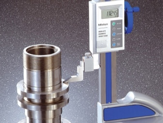
You can use this type of marking and measuring tools in locksmiths and turning workshops to determine the linear geometric dimensions of various parts, the depth of grooves and holes, as well as when marking workpieces and parts during assembly and repair work in the relevant industries (mechanical engineering, metalworking, automotive ). In addition, the height gauge is designed to accurately measure the height of parts placed on a marking area. At the same time, the metrological characteristics of the instrument are subject to periodic verification, the method of which is determined by the state standard.
They can take vertical, horizontal and even oblique measurements. True, for the latter, an additional node is needed.
How to achieve maximum precision in operations
Observe the following guidelines.
-
Only touch the height gages at the points that are specifically designed for this. These include:
-
a pen;
-
control reference plate;
-
a switch activating pneumatic bearings;
-
It is forbidden to touch other elements of the device during measurement or marking.
The accuracy of measurements and markings is greatly influenced by the ambient temperature. Due to this:
-
carry out operations only at an air temperature from +10 to +20 ° C;
-
make sure that direct sunlight does not fall on the device;
-
there should be no drafts in the measurement and marking room;
-
do not install height gages near heating devices;
-
do not measure too hot or cold parts;
-
before carrying out operations, give the instrument time to adapt if it was brought from anywhere.
Depending on the size of the workpieces, the adaptation period can vary from 15 minutes to 8 hours.
-
When two bodies touch, vibrations imperceptible to the naked eye occur. Therefore, you need to wait a little before reading the results.
-
Don't press too hard. The leg may bend. Even an imperceptible bend will lead to marriage.
Types of height gauges
According to GOST 164-90, height gauges can
produced in three versions, differing in the type of reading device.
The frame feed is the same in all cases and is micrometric.
Tools of the first type are equipped with a vernier scale and
marked with the letter combination ШР. Vernier length can be 9, 19 and 39
mm or 19 and 39 mm depending on how important vernier counting
(0.1 and 0.05 mm, respectively). Long strokes on the vernier can
be signed with whole numbers, however, denote a fraction of a whole division.
Height gauges equipped with a reading device in
the form of a circular scale, produced under the brand name ShRK. The reading device must
ensure the alignment of the arrow with the zero mark of the dial. Distance
between the edge of the marks and the arrow should not exceed 0.7 mm, and the risk of division
- be less than 1 mm.
The third type of height gauge - ШРЦ - are supplied with electronic
(digital) readout device, interface for outputting readings to an external
device (PC) and built-in power supply. ShRTs type tool is designed
for full or partial automation of measurements and ensure correct
indications when moving the frame at a speed exceeding 0.5 m / s.

