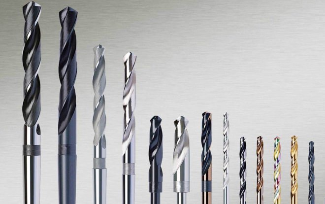
Advantage
Plexiglass is a very light material, but with a high viscosity. On the one hand, in cases where the appearance of the hole does not matter, you can drill it with an ordinary nail inserted into a drill. On the other hand, when even, smooth edges and high precision are required, great accuracy is needed.
Unlike a conical drill or a countersink twist drill, as a rule, it works at a high speed - up to 10,000 rpm. At this speed, the material heats up and partially deforms. Matt edges, for example, are an unavoidable drilling result. If you do not follow the rules for handling the tool - cooling, chip removal, the drill can be broken.
When drilling plexiglass, the viscous material wraps around the tip and hardens, the rotation is blocked. If the tool is not turned off, the drill is likely to break. In addition, it is almost impossible to extract the broken off fragment from the glass mass without cutting it.
However, using a properly sharpened tool will ensure you get straight, accurate holes and will not require reaming or countersinking in the future.
Scope of application
Drills are used for making through and blind holes, as well as for reaming - enlarging or calibrating already formed holes.
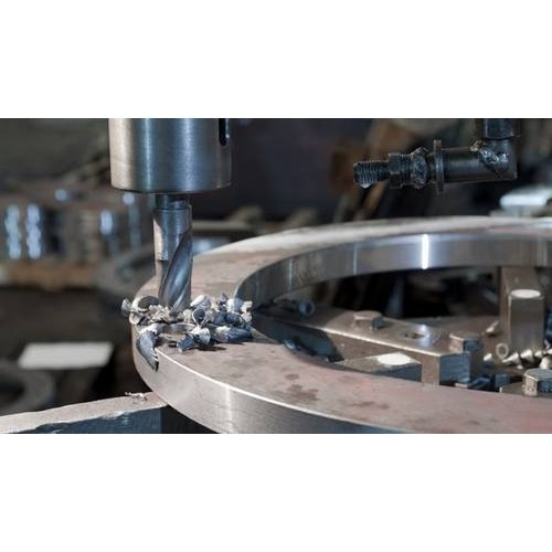
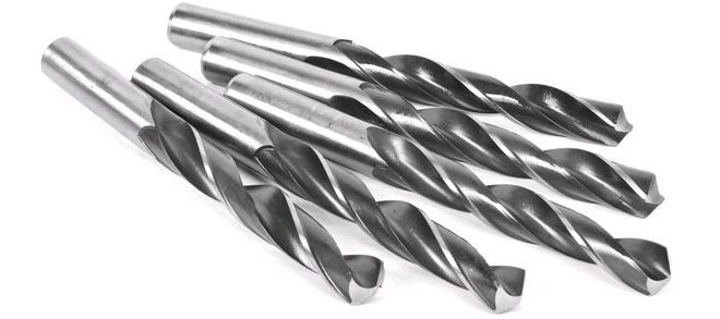
The photo shows the process of drilling plexiglass with a cylindrical drill
The use of this or that tool is determined by the material of manufacture, the method of production - solid, welded, with solid-state plates, a combination of sharpening angles, as well as the diameter and depth of drilling.
The general classification by application divides drills into the following groups.
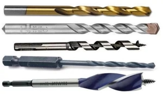
- Drills for metal - sometimes they are called universal. Since the drill is designed to work with metals and alloys, which are often of exceptional strength or hardness, they can drill any material. For plexiglass, for example, standard HSS drills are used, but with a different sharpening.
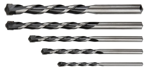
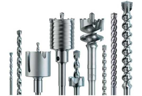
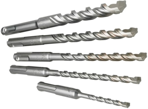
- For concrete - also used for drilling brick and stone. They are distinguished by a tip made of hard alloy, as they are designed to work with the shock-rotational method. The shank is cylindrical - in the vast majority of cases, the tool is used in rotary hammers and drills.
- For glass and ceramics - these materials are both hard and brittle, so their drilling requires accuracy. Use core drills or perforated drills (without a screw thread) with carbide or diamond spraying.
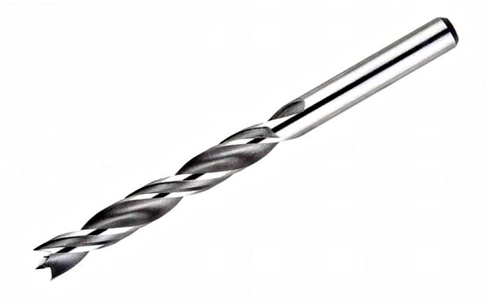
- For wood, these are standard spiral or feathers; both types are used to work with plexiglass.
We analyze the pros and cons of the tool
| Appointment | The form | pros | Minuses |
| For metal | Conical | Allow to carry out work in one stage | Not suitable for low power drills |
| Stepped | Suitable for creating recesses of different widths. Drilling in one pass is enough | Only used for sheet metal with a thickness not exceeding 2 mm | |
| Spiral | Reliable, keep sharpening well | Requires the use of products of different thicknesses to create the desired hole diameter | |
| Crowned | Suitable for creating large recesses over 30 mm wide | Incompatible with conventional drills | |
| By wood | Hole saws | Can be used for PVC lining, expanded polystyrene and cellular polycarbonate | Installation of socket outlets in the surface of OSB or lining requires reworking the hole with a jigsaw |
| Spiral for wood | Produces high quality depressions without torn fibers | Limited scope | |
| Screw | Provides a neat and clean cut, even on damp wood | ||
| Ballerinas | Provide the ability to adjust the diameter of the future hole | ||
| Perovs | Produces clean edges, no torn wood fibers | When creating a hole of small depth, a groove from the point remains in its central part. The tool only works at low speeds | |
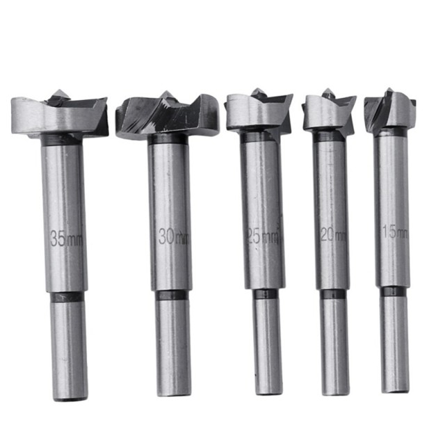
| Forstner drills | Create recesses with neat edges and a flat bottom | ||
| Over concrete, brick and stone | Spiral | Works well with concrete and brick | |
| Crowned | Do the job well | Requires hammer drilling, therefore not suitable for standard drills | |
| Screw | Designed for good dust extraction | ||
| On tiles and glass | Crowned | Large diameter range | Requires smooth surface contact, no wobbling or uneven pressure |
| Perovs | Strength of alloys in construction | Small selection of diameters for drilling |
2 Drills with cylindrical shank
Twist drills with cylindrical shank are produced in short, medium and long series according to the relevant standards. This variety provides the optimal selection of the right tool for each specific task.
For all drills, center holes are made in accordance with GOST 14034. It is permissible to produce a tool without centering holes. Medium and long series products can be produced with or without a neck according to their standards. Its size is not regulated.
GOST 4010-77 applies to left and right short series drills with a diameter of 0.5–40 mm. According to this standard, depending on the diameter of the produced drill, the length is (mm):
- the total of the entire instrument is 20-200;
- working part - 3–100.
GOST 10902-77 applies to left and right drills of the middle series with a diameter of 0.25–20 mm. Length is (mm):
- the total of the entire instrument is 19–205;
- working part - 3–140.
GOST 886-77 applies to long series drills with a diameter of 1–31.5 mm. Length is (mm):
- the total of the entire instrument is 56–316;
- working part - 33–207.
For these products, the direction of the spiral is right. The left ones are made by agreement with the customer.
For all this tool, the technical requirements for manufacturing are regulated by GOST 2034-80. According to this document, these drills are made of high-speed steel and are intended for drilling holes in ductile and gray cast irons, alloyed and carbon structural and tool steels, structural steels of high and increased machinability. This tool is manufactured in 3 classes of accuracy:
- high accuracy - A1;
- normal - B1;
- normal - V.
In addition to tools made of high-speed steel, drills can also be manufactured from alloy steel 9XC at the customer's request. The tool can be produced not only in one piece, but also welded. Shanks of welded products should be made of steel 45 or 40X. Not allowed in the welding zone: lack of penetration, surface cavities and ring cracks.
2 Conical drill for metal - varieties
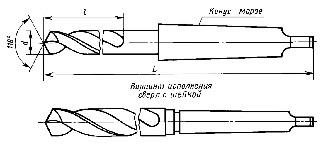
The shank tool taper is the most common. It is easy and quick to remove and easy to use. Most often it is used for CNC machines or for machines where automatic tool changes take place. There are certain norms and standards for the manufacture of these types of drills. Shortened shank tapers are obtained by reducing the thicker part of the taper. Usually, when purchasing, you can see the marking of these devices. They are designated: B7 (shortened to 14 mm), B10, B12 (shortened to 18 and 22 mm), B16, B18 (shortened to 29 and 37 mm), B22, B24 (shortened to 45 and 55 mm). A brand of conical drill with shortening is selected depending on the work, that is, on the depth of the hole being made. There are also extended taper shank drills.
Tapered shanks with an angle greater than 1 degree and a 1 to 20 ratio to the tip are defined as metric tapers.By their design, they do not differ from Morse cones. They also come in different sizes and numbers: No. 80, 100, 120, 160, 200. Most often, shanks with a Morse taper are used when working with holes. They were first proposed by Stephen Morse (the first inventor of drills). They appeared in 1864. The inventor already then proposed eight basic sizes from KM0 to KM7. Our craftsmen prefer metric cones. This is probably due to the fact that they are described in the domestic GOST, according to which most of the technical instructions at enterprises are drawn up.
Taper shanks can be presented in different designs: with feet, threads or without feet and threads. Devices with legs are attached to the spindle by jamming these legs, usually there is a special groove in the sleeve of the spindles. The purpose of the legs is to facilitate knocking out the cone from the spindle, as well as to prevent turning. Devices with an internal thread are mounted in the spindle using a stem (pull rod), which is screwed into the end of the cone. The use of threaded tapers is a guarantee that the tool will not fall out. In addition, their use will facilitate the removal of the cone if it is jammed in the spindle during operation.
Drill sharpening
The shape of the drill is selected depending on its diameter and the material being processed. For drills with a diameter of up to 12 mm, apply:
- Single sharpening - for drilling steel and cast iron;
- Single with a transverse edge for steel and non-hard steel castings with unbroken skin.
For drills with a diameter of more than 12 mm, apply:
- Single sharpening with a transverse edge and tape sharpening - for hard steels;
- Double sharpening with a transverse edge sharpening - for cast steel and cast iron with an unbroken crust.
- Double with cross-edge and tape sharpening for hard steels, steel and cast iron with removed crust.
Drill angle
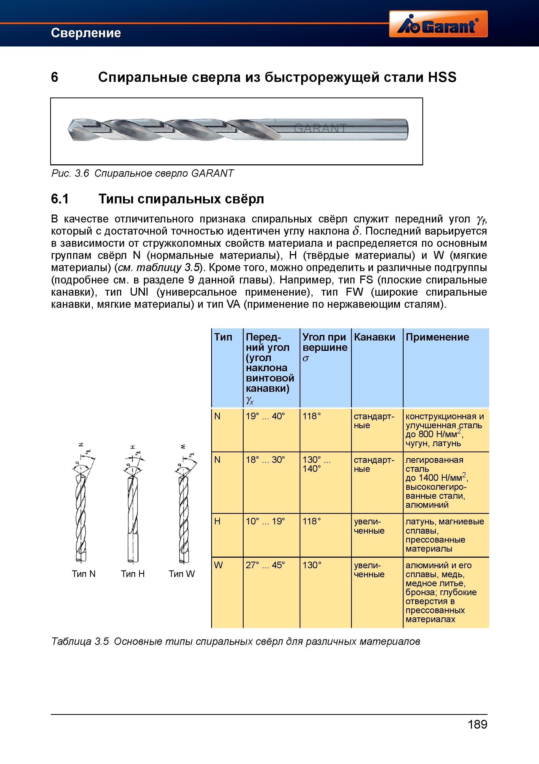
Double angles of inclination of the drill depend on the type of work material.
| Processed material | Double angle in plan 2F |
|---|---|
| Cast iron, steel, hard bronze | 116 – 118 |
| Red copper | 125 |
| Soft bronze | 130 |
| Aluminum, silumin | 130 – 140 |
| Brittle materials (Marble, etc.) | 80 |
The drill is sharpened on sharpening machines or manually on emery; in the second case, it will not be possible to accurately maintain the angle without the use of special devices.
The diameter of the drill, as a rule, is chosen slightly smaller than the diameter of the hole to be produced, this is due to the fact that the hole is broken during drilling.
Drill types for metal
- Spiral (common and most popular)
- Crowned
- Conical or stepped, or as they call it conical
- Perforated drill
Here we have divided the drills according to their appearance. This will be the main criterion. Now let's go over in general terms the types that we have identified, in which situations we will use these or those types of drills when working with metal.
Spiral
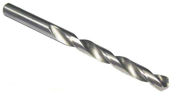
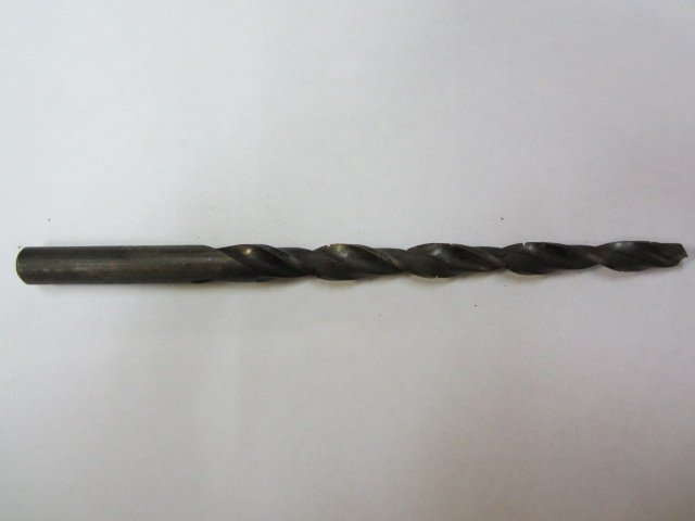
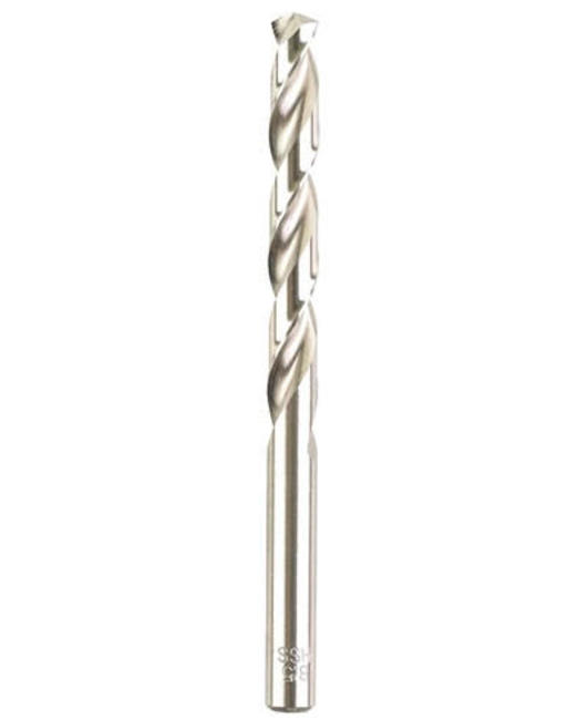
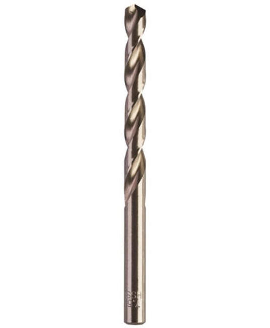
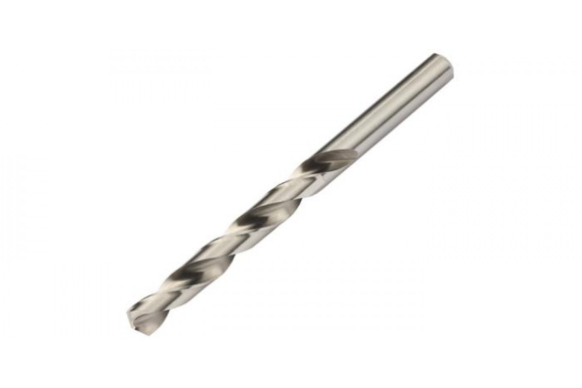
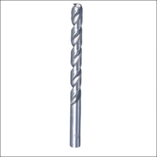
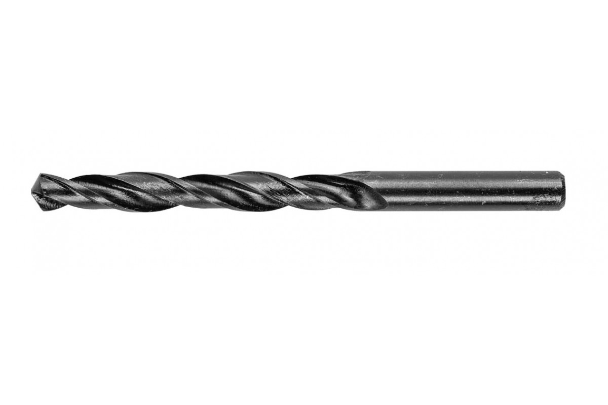
Twist drills for metal are the most popular, and not only when working with metal. They have high precision and quality when drilling holes. Twist drills are a cylindrical view with spiral grooves that are located along the entire working area. They allow the removal of metal chips from the hole to be drilled. At the end of the working area, there are usually two edges that cut the metal. Due to them, the drill makes holes in the metal.
Twist drills can be used on both a drilling machine and a hand drill. On the machine, the accuracy of your work will be higher.
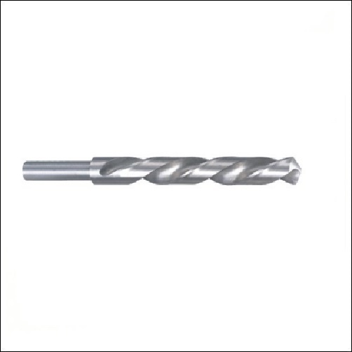
Twist drills for metal come with a cylindrical shank and canon and hex.
Metal drill with canon shank
If you look at the performance of the twist drill, the following groups can be distinguished:
- High precision twist drills. These drills are used by artisans who need a high level of precision when drilling. Having bought such a drill, you will be sure of the accuracy to microns, in the diameter of the hole. Drills of increased accuracy can be recognized by the A1 marking stamped on their base.
- Left hand twist drill. To answer the question of what they are used for, you can recall a situation that happened to many, namely when the head of the bolt breaks off. It is not possible to unscrew its base. It is for such cases that the left-hand spiral sveto is intended - it helps to unscrew the broken off bolts and studs. Someone will have a question how to distinguish a left-hand drill from a conventional one - for this it is enough to look in which direction its working area is twisted.
- Twist drills for metal for general use. This is the type that we use most often. They have a wide range of working diameters, up to 80mm. Such drills are often used both in everyday life and in production.
Core drills
Core drills for metal allow you to make holes in metal of large diameters. Due to the fact that when using them, only the outer part of the diameter is cut, the energy consumption for drilling is minimal. This allows larger holes to be drilled faster than with twist drills. In the middle of the core drill is a conventional twist drill for centering. They allow holes up to 15 centimeters in diameter to be drilled.
In appearance, the metal core drill looks like a glass, with grooves on the outside, for removing chips. And with a centering drill. At the end of the bit there are cutting teeth, which are made of hard metal and diamond-coated.
Conical (stepped, conical)
The step or cone drill got its name from its appearance. It looks like a cone. The taper of a stepped drill can be either smooth or steps. A conical step drill for metal is universal, since one such drill can make holes of different diameters. It is used for drilling holes of various diameters, or for enlarging a hole in thin metals, mainly up to 4mm. At the end, the taper drill has a centering tip, which allows you to immediately start drilling in the right place, without shifting.
Conical drills come in a variety of diameters, ranging from 4mm to 32mm.
Drill bit for metal
The pen drill for metal has a flat working part, and it is replaceable. A replacement insert for a metal nib drill can be purchased separately when the old one is dull.
Of the pluses of the pen drill, its low cost can be emphasized, which makes it popular for use at home.
The disadvantage of the first drill is the lack of chip removal, which gives some inconvenience during work. During drilling, you will have to stop more often and get the feather drill out of the hole to remove the chips.
Drill characteristics
 The tool can differ in design and size, color and sharpening angle.
The main indicator of any drill is its strength. It should be higher than the surface to be treated.
An important component is the shank, which is matched to the chuck of the equipment used.
Material
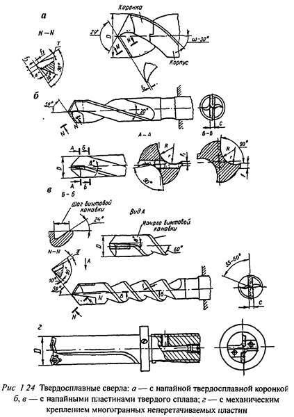
Components are manufactured from various types of alloys. Used high speed steel P9, P18 and P9K15. For elements with a width of more than 8 mm, special welding is used. The hard source is usually processed with cobalt-based fixtures. Carbide Victory bits are suitable for working with brick, concrete and stone.
The composition may contain molybdenum, chromium and vanadium.
Coating
To increase the service life, special coatings are applied to the parts:
- Oxide film - protects against overheating during intense friction and rust.
- Diamond spraying - has maximum durability, is used for components processing hard coatings.
- Titanium shell - combines three groups of coatings (TiN, TiCN, TiAIN).
Coloration
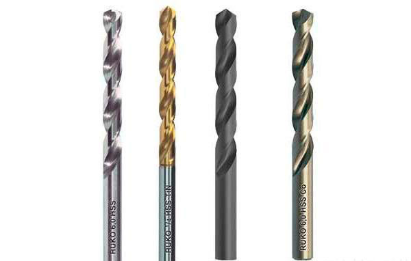 Borax color is also important
The color determines the type of coating and the technology of creation:
Gray is the natural shade of the steel body. Such parts have not been processed, which means they have a low price and a short service life.
Black - steel body exposed to superheated steam. Such products are more durable.
Yellow - a component that has passed the stage of tempering (reduction of internal pressure). Such a workpiece has a high hardness index.
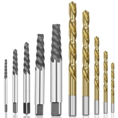
Golden - a shade of titanium nitride. Workpieces with this color are characterized by increased strength and low friction.
Weight and size
The range of manufactured components is quite large and their dimensions depend on the purpose.
The most popular models come in the following sizes:
- Long - 5.6-25.4 cm, with a diameter of 1-20 mm.
- Elongated - 1.9-20.5 cm, 0.3-20 mm wide.
- Short - 2-13.1 cm, with a diameter of 0.3-20 mm.
The weight of the fixtures is determined by the design, the material in the composition and the size. Standard options reach weights from several units to tens of grams.
Features and Geometry of the Twist Drill
Processing of workpieces on drilling machines is carried out with drills, countersinks, reamers, taps and combined tools.
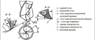
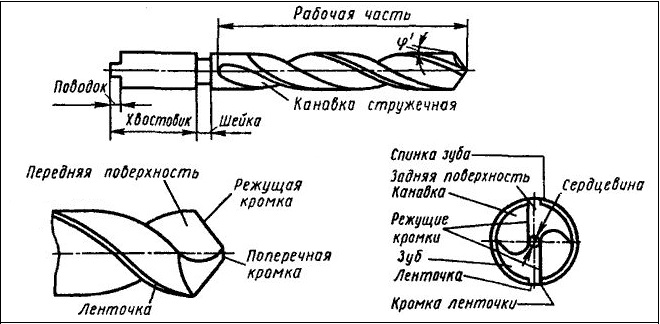
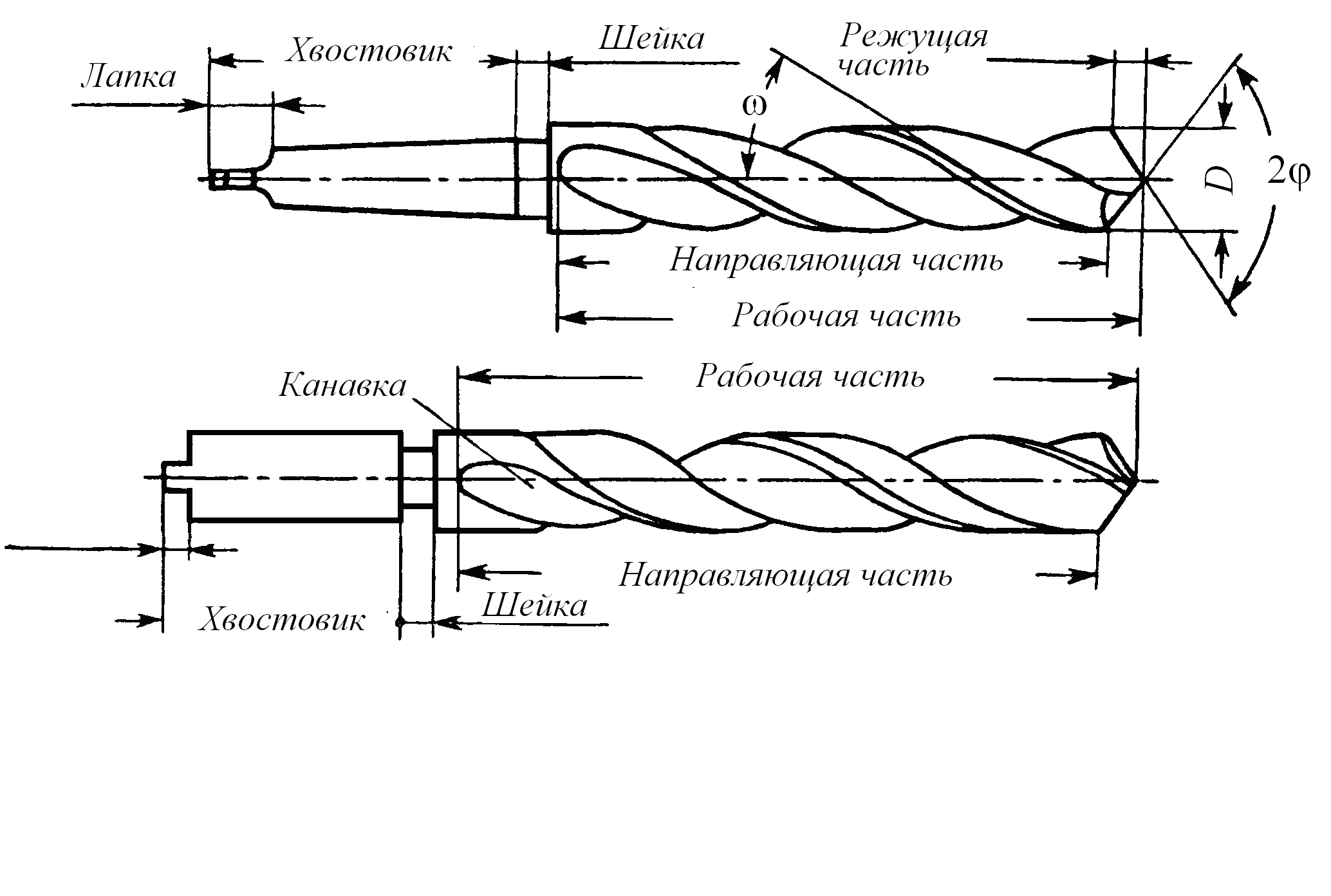
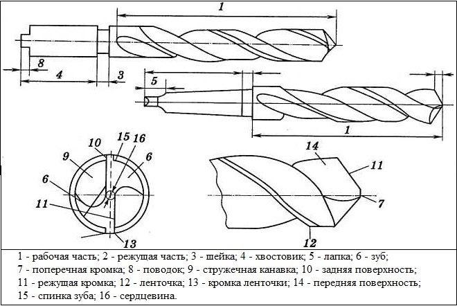
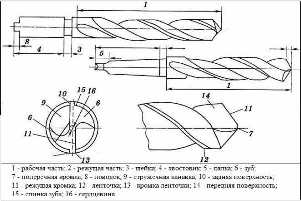
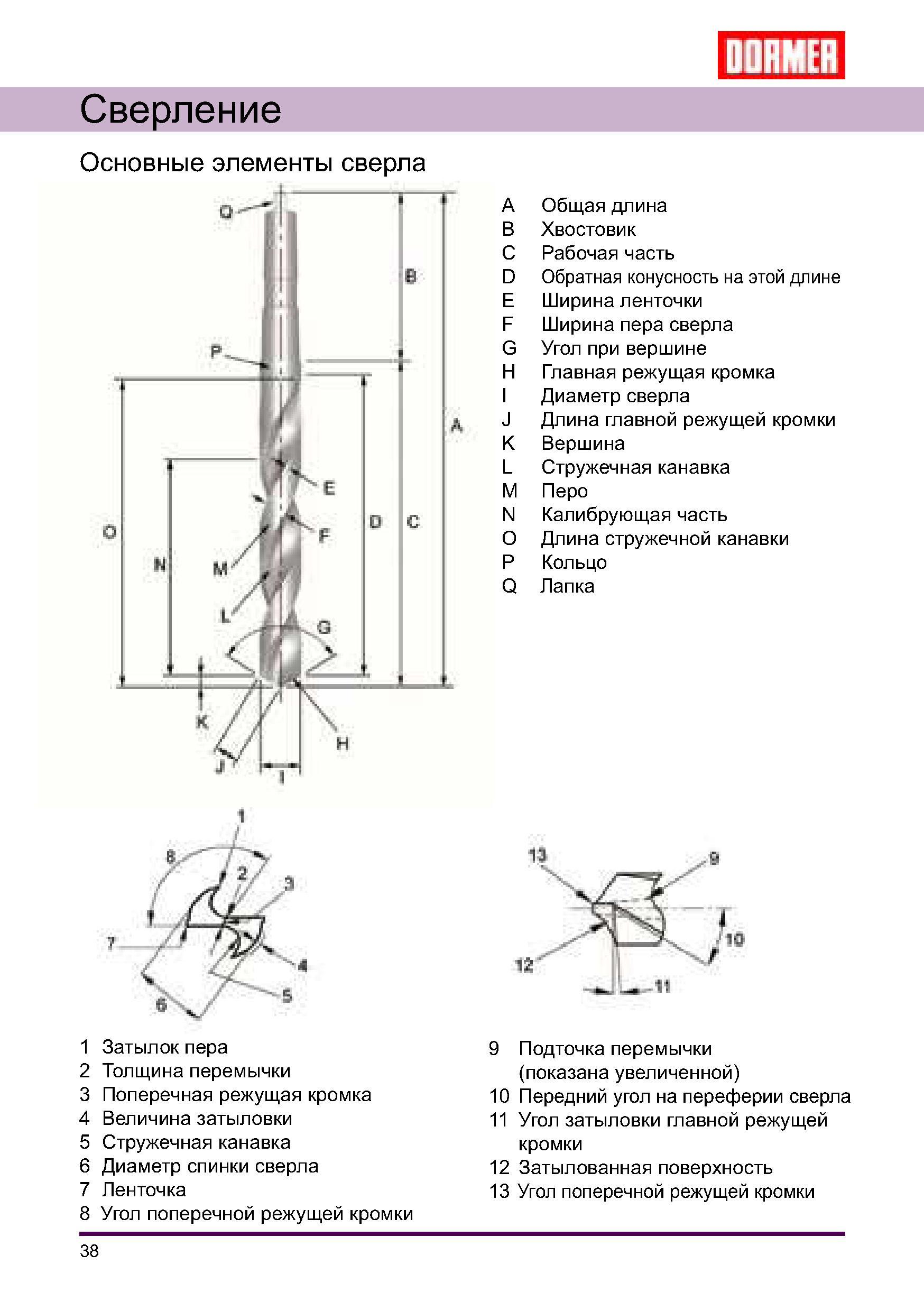
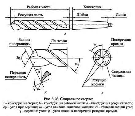
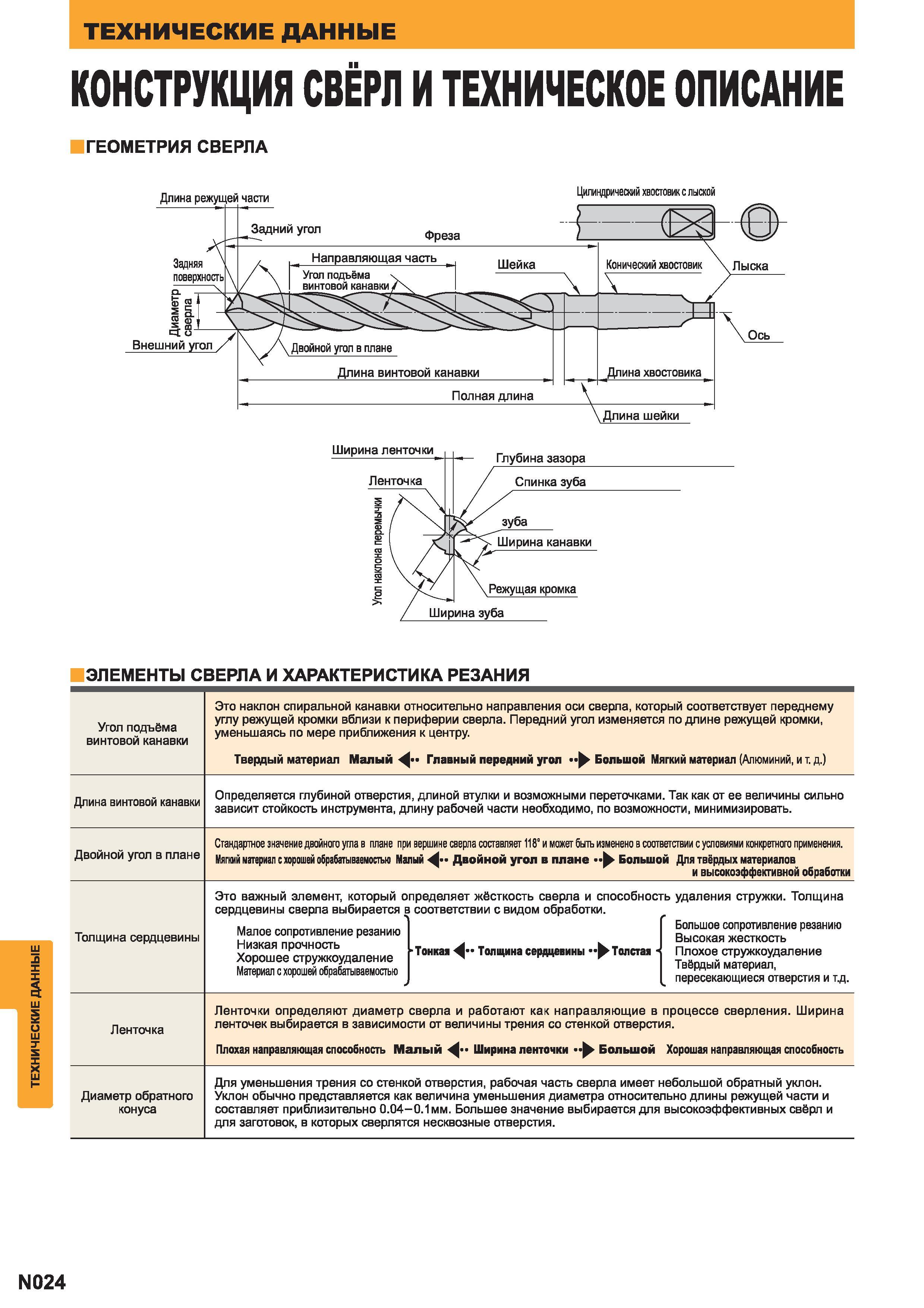
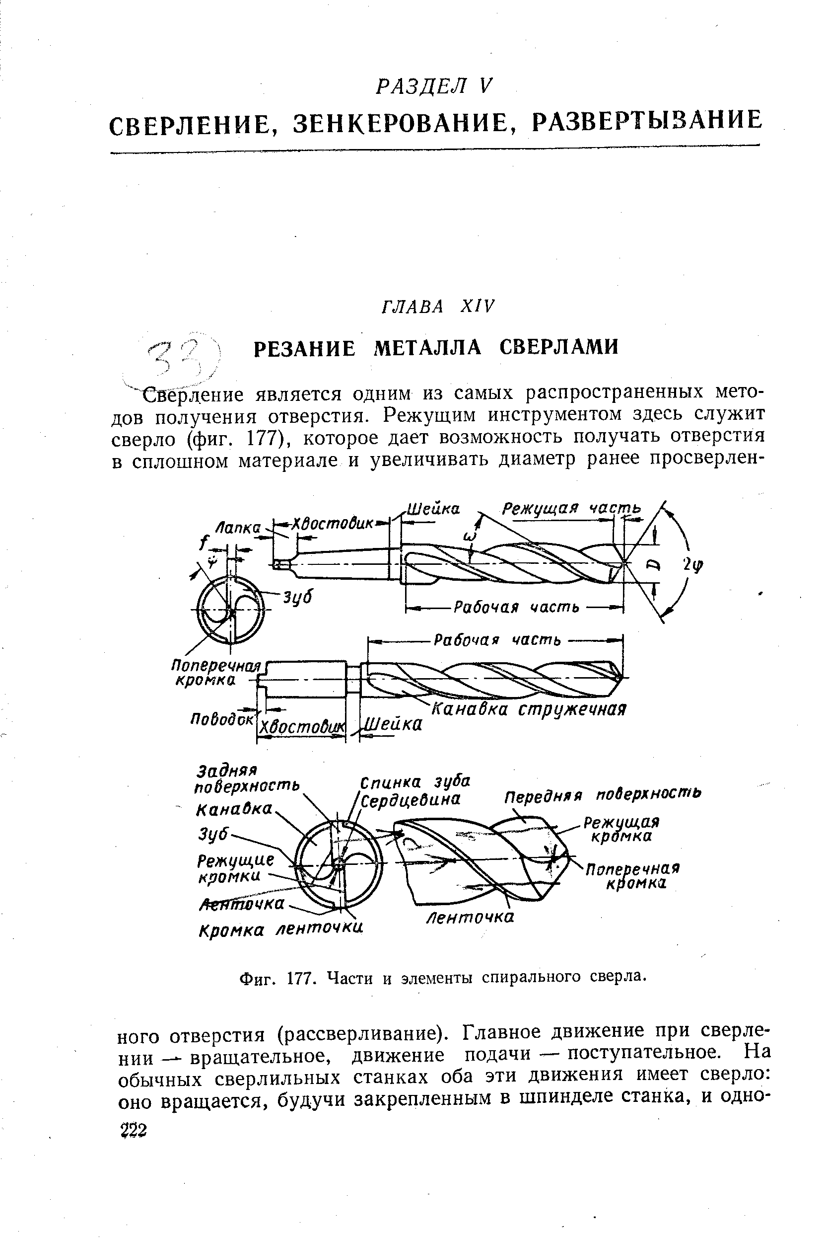
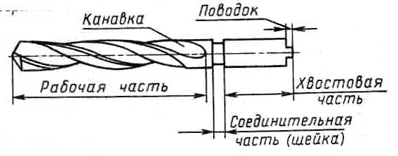
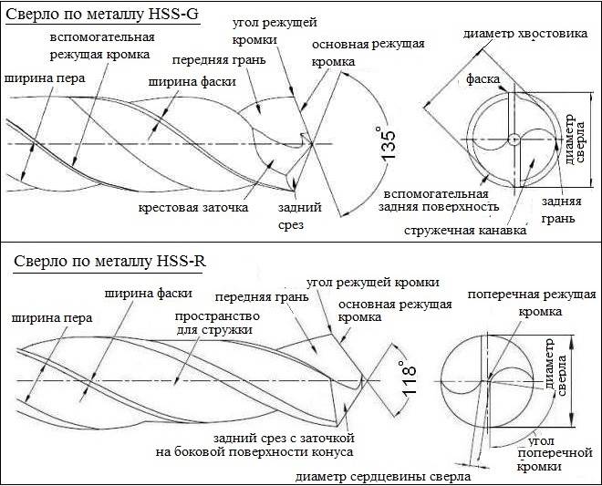
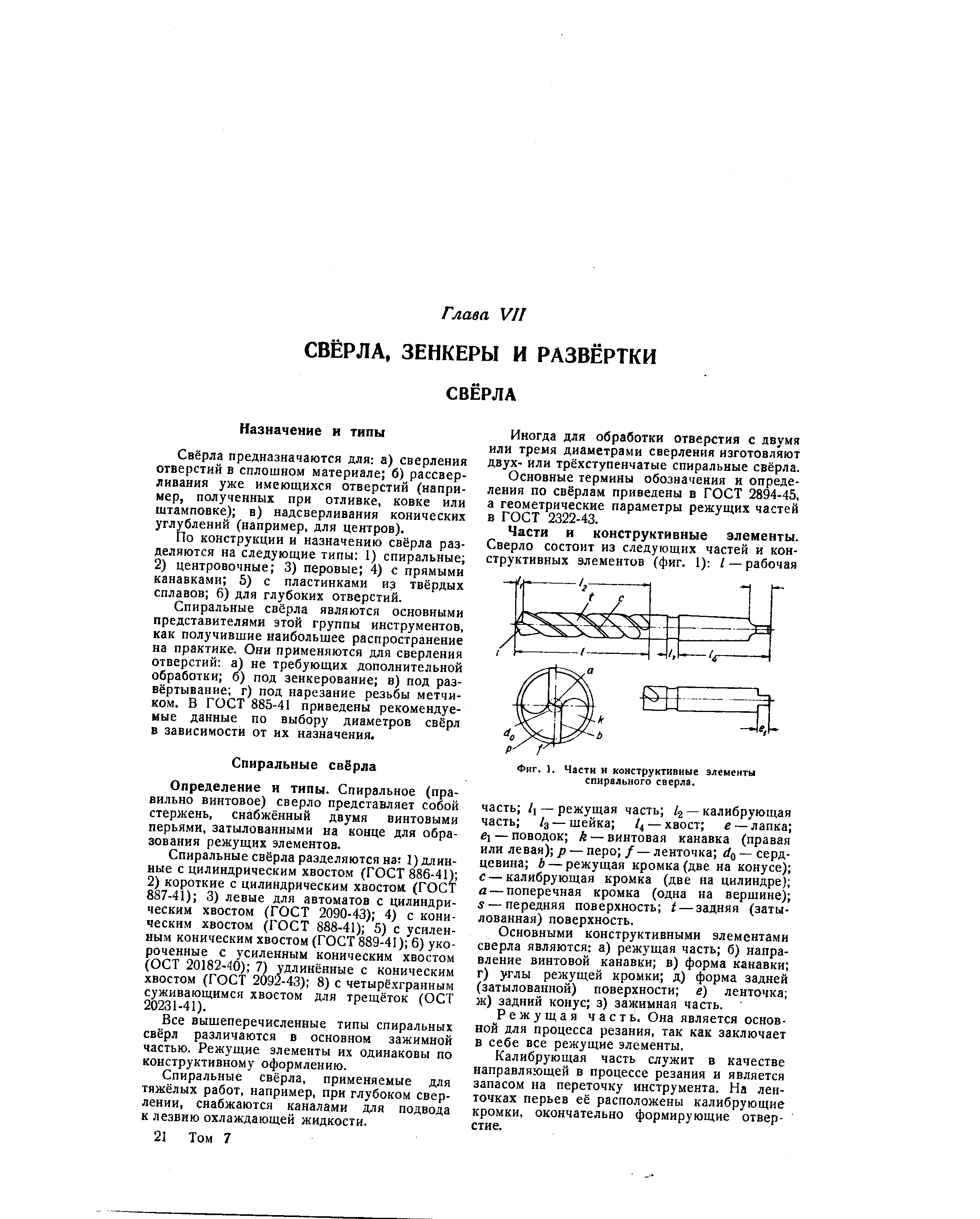
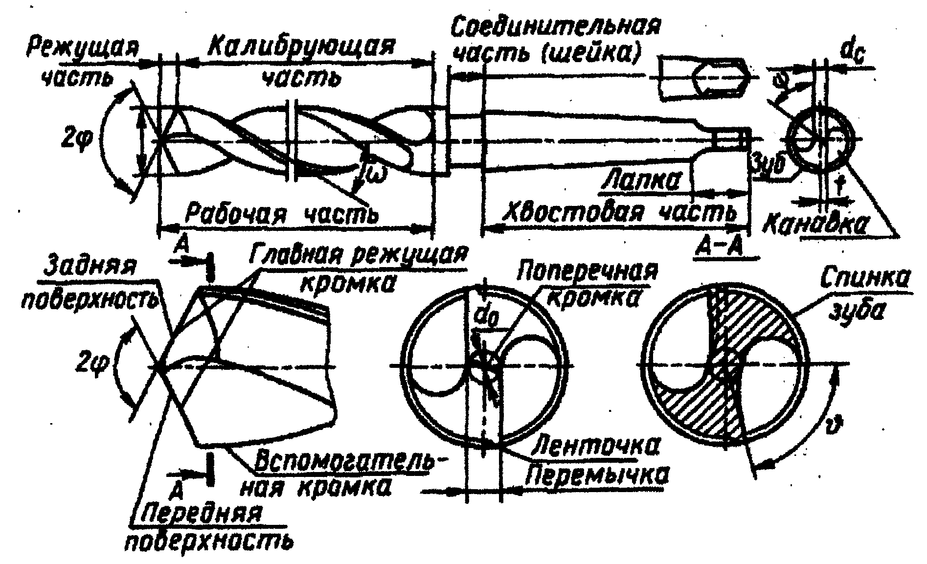
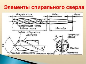
By design, drills are divided into spiral, centering and special. The most widespread are twist drills (Fig. 22.12), consisting of a working part b, a neck 2, a shank 4 and a foot 3. “The purpose of the shank is to secure the drill in the spindle. The foot is used to knock out the drill from the spindle and protect the shank from nicks. The working part consists of a cutting 1 and a guide 5 parts. To avoid pinching the drill, a reverse taper is made on it towards the shank. On the cutting part there are two main cutting edges 11 (formed by the intersection of the front 10 and rear 7 surfaces and performing the main cutting work), a transverse cutting edge 12 (bridge) and two auxiliary cutting edges 9. On the cylindrical part of the drill along the helical groove, two narrow ribbons are located 8 to guide the drill while cutting.
The geometrical parameters of the drill determine the conditions for its operation. The rake angle y is measured in the main cutting plane.
| 1 2 3 Fig. 22.12. Parts, elements and corners of the twist drill |
II — II, perpendicular to the main cutting edge. The clearance angle a is measured in the I — I plane parallel to the drill axis. The front and back corners at different points of the main cutting edge are different. At the outer surface of the drill, the angle y is the largest, and the angle a is the smallest.
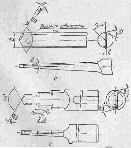
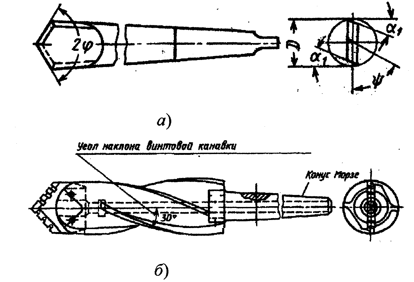
The angle at the tip of the drill 2ph is measured between the main cutting edges. Its value depends on the material being processed and varies within 70.150 °.
The angle of inclination of the transverse cutting edge y is measured between the projections of the main and transverse cutting edges on a plane perpendicular to the axis of the drill. For standard drills, it fluctuates between 50.55 °.
The angle of inclination of the helical groove c is measured by the outer diameter. With an increase in the angle ω, the rake angle y increases, which facilitates the cutting process and the exit of chips. The angle y is 8.30 °.
Holes with a diameter of up to 80 mm are drilled, and holes with a diameter of up to 30 mm are drilled, and large holes are reamed. Drilling is used as a pre-treatment for precision holes.
Countersinks (Fig. 22.13, a-c) process holes in cast or stamped blanks, as well as pre-drilled holes. Unlike drills, countersinks have three or four main cutting edges and do not have a transverse edge. The cutting part 1 does the main cutting work. The calibrating part 5 serves to guide the countersink in the hole and provides the required accuracy and surface roughness (the rest of the legend is the same as for the drill).
a 1 2 h b  |
 |
 Rice. 22.13. Tool for processing holes on drilling machines: a-c - countersinks; g-e — sweep; w - tap Rice. 22.13. Tool for processing holes on drilling machines: a-c - countersinks; g-e — sweep; w - tap |
By the type of holes to be machined, countersinks are divided into cylindrical (Figure 22.13, a), conical (Figure 22.13, b) and end (Figure 22.13, c). Countersinks are solid with a tapered shank (Fig. 22.13, b) and mounted (Fig. 22.13, c). Holes with a diameter of 20.40 mm are processed with efficient, and over 30 mm - with mounted countersinks.
The final processing of the hole is carried out with reamers. According to the shape of the hole being machined, cylindrical (Figure 22.13, d) and conical (Figure 22.13, d) reamers are distinguished. The reamers have 6.12 main cutting edges located on the cutting part 7 with a guiding cone. The calibrating part 8 guides the reamer in the hole and provides the required accuracy and surface roughness.
According to the design of the fastening, the reamers are divided into tail (Figure 22.13, d, e) and mounted (Figure 22.13, e).
Taps are used for cutting internal threads. The tap is a screw with cut straight or helical grooves that form cutting edges (Figure 22.13, g). The tap consists of 9 cutting and 10 gauging parts. The thread profile of the tap must match the profile of the thread to be cut.
Didn't find what you were looking for? Use the search:
Best sayings: A student is a person who constantly postpones inevitability. 10805 - | 7379 - or read everything.
95.47.253.202 Not the author of the materials that are posted. But it provides an opportunity for free use. Is there a copyright infringement? Write to us | Feedback.
Disable adBlock! and refresh the page (F5)very necessary
DRILLING, COUNTERSINKING AND REAMING
As a result of studying this chapter, the student must:
- • types of drills, countersinks, countersinks, reamers;
- • structural elements and parameters of typical tools: drills, countersinks, countersinks, reamers;
- • elements of the cutting mode during processing by drilling, countersinking and reaming;
- • carry out the selection of tools for processing by drilling, countersinking and reaming;
- • assign modes of appropriate processing;
- • calculate the cutting forces when drilling;
- • the skills of choosing a cutting mode when machining holes with axial tools (drills, countersinks, reamers);
- • methodology for calculating the cutting force when drilling;
- • the skills of determining the power required for cutting and the power of the drive of the main movement.

