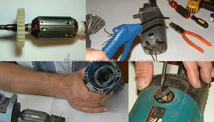
How to check the stator winding of the angle grinder at home in different ways
There are a large number of different electrical devices with which you can diagnose the stator. However, at home, a limited number of technical means are used. Some are presented in the following videos.
Checking the armature / rotor and stator with a multimeter / tester
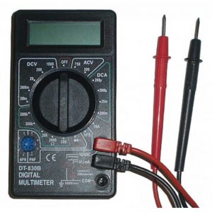
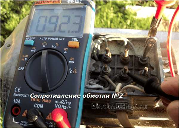
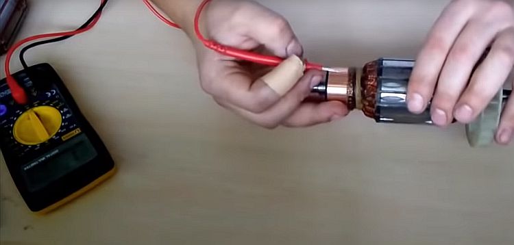
In the following video, a multimeter device, or, as more commonly called a tester, is used as a tool for diagnosing the rotor and stator of an electric drive. It is used to measure various electrical parameters: resistance, current, voltage. To determine faults in the form of wire breakage, breakdown of the winding to the case, the "ohmmeter" mode is used, that is, a certain resistance value is set, which is comparable to that available in the tested circuit. In this case, with a limit of 200 ohms.
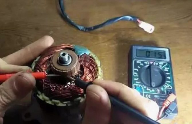
Breakdown of the stator to the housing is determined by applying indicator probes to its housing and one of the ends of the winding. The presence of any resistance value on the indicator indicates the presence of a defect in the form of a breakdown of the winding onto the case. When diagnosing a winding break, the indicator of the device will not show anything when the probes are combined with the winding leads.
More complex manipulations should be carried out when checking the rotor windings of the electric drive. A winding break can be in any connection with a separate collector lamella. Therefore, it is necessary to check the resistance between all lamellas of the collector, applying indicator probes to them one by one. In the absence of an open circuit, the resistance will have the same small value in all cases. Any deviation indicates the presence of a cliff. The breakdown of the winding on the case is checked with probes when they come into contact with the collector and "iron" from a set of sheets of electrical steel. The indicator scale should not react to this action.
However, it is impossible to determine the turn-to-turn circuit with a multimeter. Here, a device called the indicator of short-circuited loops (IKZ) is used. More details about it in the information below.
On turn-to-turn circuit, indicator
The principle of operation of the device for determining the turn-to-turn closure is shown in the following video. The device in the tested winding induces a magnetic field. In the presence of short-circuited turns in the winding, the short-circuit current causes increased resistance to the electromagnetic field generated by the device. By adjusting the IKZ, a setting is performed, upon reaching which a light signal is triggered (the indicator lamp changes color from green to red) or a sound is heard. In addition to the main application, the author shows a way to determine the places of connection of the winding wires to the collector lamellas, in the absence of visually visible contacts.
Makita, without instruments
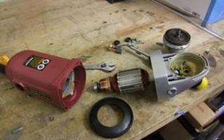
In one of the Makita models in the next video, smoke went off during operation, which is a sure sign of a burnt out rotor or stator. To determine the reasons, the author performed a complete disassembly of the grinder, which makes it possible to perform a good external examination of the grinder units suspected of malfunctioning. If there were no signs of smoke consequences on the rotor, then on the stator several places of burnt electrical insulating varnish were clearly visible.
Multimeter - automatic: quickly and efficiently performs measurements
The multimeter, which is presented in the next video, is convenient to use and allows you to take readings without unnecessary fuss, when the measured values "jump" at a device that does not have such an option. A method for determining the measurement error associated with the resistance of the indicator probes is shown. The approximate value of the winding resistance is given, where there are no faults.
It does not take much time to check the stator and rotor for turn-to-turn circuit with a multimeter. It will take longer to disassemble the engine. Grinder, drill, perforator - each tool can be repaired by identifying a malfunction. It is better to break the check into several main stages, and consistently slowly perform the actions.
How to rewind at home?
If the integrity of the rotor winding is violated, it must be carefully removed using pliers, a hacksaw for metal, a chisel, nippers - all the necessary tools. Avoid damaging the collector contacts, the iron base of the winding and the armature shaft. Before deleting, find out what the winding scheme is and fix this fact on paper. In the process, follow the drawn winding direction diagram.
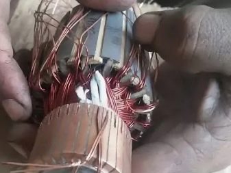
The winding wire is placed in special grooves in the iron base. It is necessary to calculate how many conductors are in each groove and, based on this, calculate the number of turns. In the standard version, they should be 2000 - 2300. Cardboard plates are inserted into the grooves, insulating the winding from contact with the iron base. Then the wire is wound, the ends of which are soldered to the collector contacts upon completion.

Before impregnating a new winding, it is necessary to ring it with a multimeter or tester in order to exclude the presence of a breakdown. If there is none, the anchor is sent to the oven to warm up. The heated rotor winding is impregnated with epoxy resin. For better flow through the wire, the anchor is held at an angle.
Rotor malfunctions
In the case of optimal use, the rotor does not wear out. Routine work is carried out with the replacement of brushes when they are worn out. But over time, under heavy loads, the stator heats up and carbon deposits form. The most common mechanical failure is wear or misalignment of bearings.
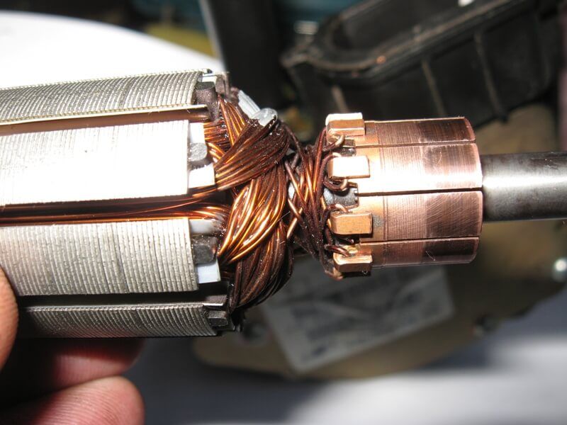
The grinder will work, but at the same time the plates wear out quickly, and over time the engine breaks down. To avoid damage, it is necessary to check the tool and maintain normal service conditions.
Moisture on contact with metal causes the formation of rust. The friction force increases, the current is required more for work. Significant heating of contact groups, solder occurs, a strong spark appears.
How to fix, repair
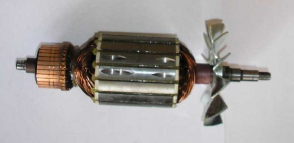
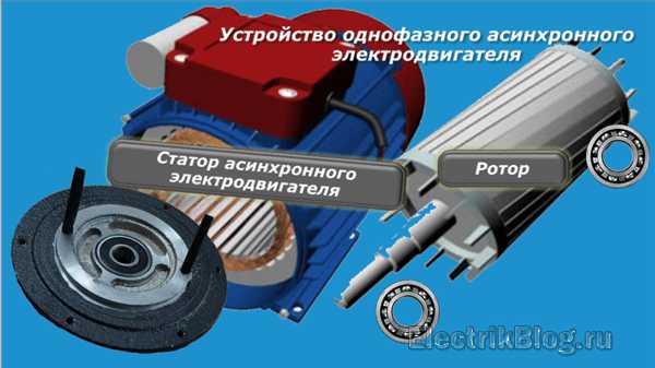
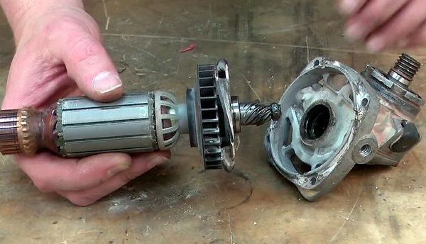
The rotor, in contrast to the stator, the main element of which is the winding, has a more complex design. In addition to the coils wound into the grooves of the core, its assembly includes bearing assemblies, a manifold, a fan and the shaft itself. This increases the number of options for malfunctions, which means that it is somewhat more difficult to repair the rotor than the stator.
Rotor winding repair
The following video describes the most common rotor repair electrical faults - damage to the winding. The author briefly describes the sequence of operations for repairing rotor windings: from diagnostics to rewinding and impregnation.
Important: the author points out a control check by devices of the correctness of each operation, where necessary.
Collector repair
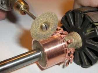
A defect that is eliminated in the next video, namely, the separation of the collector lamellas, with whole rotor windings, is not so common. However, the author brilliantly performs it at home. Instead of missing lamellas, new ones are made of copper wire by cold forging.
After soldering and gluing the lamellas, all beads are removed by locksmithing, and the final finishing of the collector surface is carried out by the original method proposed by the author. It is not always possible to find a lathe at home, so the anchor is assembled at its direct destination (grinder), where instead of brushes, a tool is installed for processing collector lamellas.
It is a piece of wood, fitted to the size, on which a sanding cloth is attached. The processing force is created by tightening the plug that presses the block by a certain amount. The rotor is driven through the spindle by another grinder. Thus, by changing the sanding paper several times, a perfectly flat and polished collector surface is achieved after replacing the lamellas.
Replacing the fan impeller
In the following video, a metal impeller hub is broken on the rotor after a foreign object has entered it. The author found a way out by assembling a new impeller from a broken one and another, taken from a burnt-out rotary hammer rotor. On a home-made device made of a drill and a vice, the extra elements were cut off with a sharp knife from the impeller from a perforator (plastic) mounted on the rotor, that is, only the hub remained. Next, a damaged impeller was riveted to the hub. During rotation, with the help of a drive, a drill, support on a bearing in a vice and a file, the required radial and end runout was set on the assembled new impeller.
The rotor sparks, the reason how to fix it
The main reasons causing increased sparking during the operation of the grinder.
- The brushes are worn out. They should be replaced, sometimes to achieve the result, together with the brush holder and the pressure spring.
- Opens, short circuits in the rotor winding. Replacing the armature or rewinding a new winding will help eliminate strong sparking. In the video, the replacement of the armature and brushes creates normal conditions for the functioning of the brush-collector assembly.
- Malfunctions in the stator winding can cause arcing. Here, by analogy with the armature, the stator winding or the stator itself should be replaced.
- Accumulation of graphite dust on or between lamellas. Regular cleaning of the lamellas with sandpaper and cleaning the graphite between them will make it impossible to create additional conditions for the appearance of a spark.
- The brushes can be installed incorrectly in relation to the collector surface and, as a result, conditions are created for the formation of a large amount of graphite dust. You can eliminate it by straightening the shifted brushes.
- When overheated, carbon deposits form on the collector, which creates conditions for poor contact of the brushes with the blades and an increase in sparking. It is necessary to clean the surface of the collector with fine-grain sandpaper, after which polishing on a felt wheel will make the work of the brush-collector assembly effective.
- Mechanical violations caused by a deviation from the technical requirements for the design of the grinder. Most of them are eliminated as, for example, in the video by grooving on a lathe.
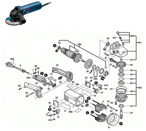
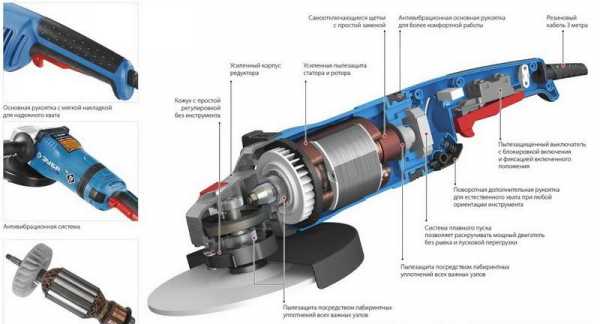
Hand grinder device
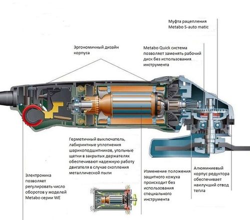
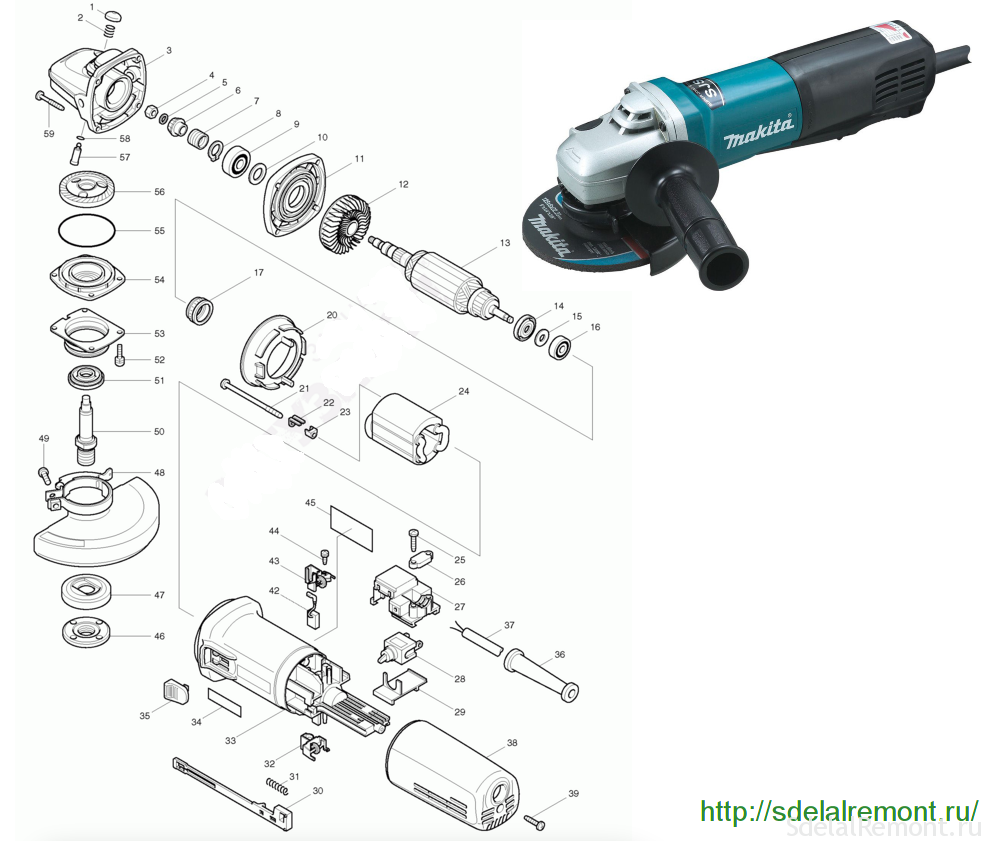
A grinding tool has three important components:
- anchor;
- reducer;
- stator.
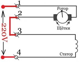
The armature is a winding rotating element and generates the torque of the electric motor. The stator, divided into sectors, has the same winding. The current through the carbon brush passes through the winding, goes to the armature. The current is then transferred to the other brushes until all parts of the stator are involved. When an electric current passes through the winding, a magnetic field constantly interacts with the stator. Thus, the electric motor is driven. There are several typical breakdowns of the grinder's launch device:
- combustion or rupture of the winding;
- short circuit between winding turns;
- destruction of insulation.
Scheme eccentric orbital sander.
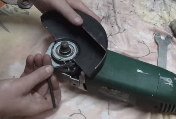
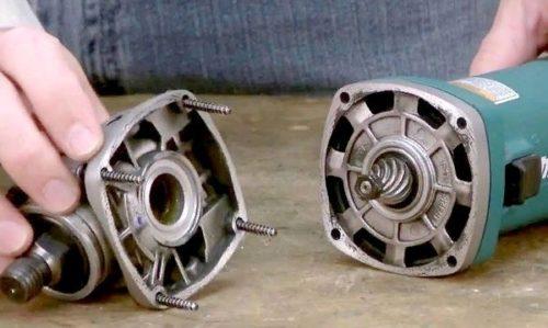
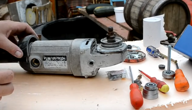
You can rewind the winding with your own hands, without contacting a specialist. You just need to disassemble the device first. But if you do not have complete confidence in your abilities, then contacting a specialized workshop will be the most reasonable step. The casing is displaced first. For this, the screw securing it is unscrewed. After that, you can see all the details of the grinder, with the exception of the gearbox hidden under the metal cover. The screws are unscrewed, with which the metal plate is fixed. All mechanical parts are now clearly visible. Only then can you proceed to rewinding the stator.
Better than a well-performed repair can only be correct operation, in which there will be no breakdowns at all. In order for the "grinder" to work longer, the following simple rules must be observed:
- In no case should the amount of grease and the timing of its addition or replacement be exceeded.
- After the tool has been running at reduced speed, it is strictly forbidden to turn it off immediately. If left to run for at least 1 minute, overheating can be avoided.
- Long-term operation of the tool at reduced speeds under load should not be allowed.
Check by the short-circuit indicator
It is possible to detect an open or short circuit in the winding using the indicator of short-circuited turns (IC). Other names are the turn-to-turn closure indicator or the indicator of defects in the windings of electrical machines.
The device consists of:
- power supply unit;
- housings with LCD display, sockets for connecting accessories;
- connecting wires;
- large induction sensor;
- small induction sensor.
The procedure for checking the stator of the grinder with the IDVI device:
- Inspect the turn-to-turn indicator. Make sure that there is no external damage, the integrity of the connecting wires and sensors.
- Connect the power supply.
- Press the power button and make sure the device is working properly.
- If the indicator of winding defects has been in the cold for a long time, then it must be kept at room temperature for at least 2 hours.
- Disconnect the power supply of the angle grinder.
- Choose from two sensors large or small depending on the stator size.
- If the rated voltage per one turn of the winding is not indicated in the passport of the angle grinder, then it must be determined by the formula: the rated voltage of the entire coil is divided by the number of turns.
- Switch on the device.
- Set on the indicator the nearest greater than that obtained during the calculation, the amplitude of the impulse test voltage.
- Pressing the sensor to the winding surface, sequentially check all the grooves, waiting for 3-4 s. When a short circuit is detected, the device will emit a sound signal, and the corresponding inscription will appear on the display.
- If short-circuited turns are not found, then set the next (larger in value) amplitude on the device and make sure that there is a margin of safety for the winding insulation.
- Switch off the device.
The winding defect indicator can be used to check the condition of the insulation between the stator and rotor coils, as well as between the stator winding and the grinder body. If it is not possible to buy a ready-made device, then you can make a simpler indicator of short-circuited turns yourself.
Grinder - rules for working with an electric grinding tool
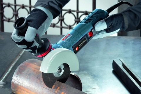
The angle grinder is called "grinder" only in the repair spaces of the former USSR for a prosaic reason - its production was solely carried out by the "Eltos-Bolgarka" plant in Plovdiv. The high-speed cut-off wheel is an indispensable assistant when processing the most durable metal, when arranging siding on the ceiling, when cutting reinforcement, sheets, profiles and many other repair operations.Grinding capabilities of grinders are no less popular - they allow you to eliminate burrs, roughness from both metal and stone or marble.
Over the past 40 years, the range of grinders has grown tremendously, but the rules for handling this convenient and multifunctional tool have not changed much. Moreover, repairs are often prevented by following simple operating recommendations:
- Do not remove the cover over the abrasive wheel unless absolutely necessary. If this cannot be avoided, be sure to work with protective goggles and protect the tool from any lateral touches;
- Do not process wood, chipboard, MDF and similar materials - there are saws and hacksaws for this;
- Hold the grinder firmly and confidently - if the disc is jammed, the entire tool can be pulled out of your hands, it will receive severe damage and entail the risk of serious injury;
- The work of any grinder is accompanied by the presence of characteristic sparks - beware of falling on electrical wiring, power cord and any other flammable materials;
- Any workpiece - cut or grinded - must be securely held in place. Even if you have to cut a reinforcing bar embedded in concrete when erecting a strip foundation from corrugated board, you should make sure that the entire structure is strong before pressing the "Start" button on the grinder;
- Do not press down on the part to speed up the work. The principle of operation of abrasive wheels is to erase the material of the workpieces and does not need a large clamping force. Precision of movement when working with a grinder is just as useful as brute force is harmful.
Mechanical damage
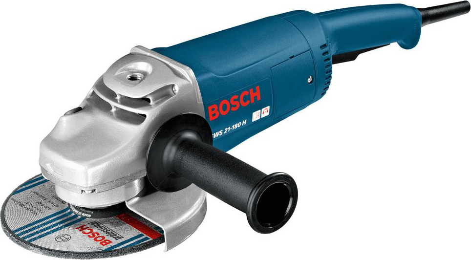
Bosch angle grinder is designed for cutting, grinding, polishing work. The operation of the tool in dust under heavy loads has a particularly detrimental effect on the durability of the gearbox, namely its gears.
In addition to wear and tear of the gear teeth, mechanical failures include the destruction of bearings and housing. Repair of a Bosch grinder in terms of replacing failed bearings, restoring the housing is easy to perform if there is a desire and need.
Assembling the grinder
The assembly of the grinder begins with an examination of all parts, assemblies, bearings, gears.
Prepare the work area in advance with correct and good lighting, place tools, lubricants, napkins.
What kind of lubricant to use for the Bosch grinder
Bosch ear repair will not be of high quality if you do not change the lubricant during its execution. For high-quality lubrication of the Bosch grinder units, it is recommended to use those lubricants offered by the tool manufacturer. But their high price makes them look for another way out, and there is one.
Domestic lubricant manufacturers have developed special gear lubricants and knots of grinders.
In terms of quality, they are in no way inferior to foreign lubricants, and are much cheaper. The only drawback is that our greases require more frequent changes.
Or you can use a hand-made lubricant.
Rotor assembly
The assembly of the rotor consists in pressing the bearings onto it, installing the impeller. The lubricated bearings are pressed onto the shaft using a wooden adapter. The bearing near the manifold is covered with a rubber protector. This is the general algorithm for assembling the rotor shaft.
Certain models of Bosch grinders have their own characteristics.
Gearbox assembly
The assembly of the gearbox begins with the installation of the rotor shaft in its housing. When the shaft is inserted into the housing, the drive gear, washer, and retaining nut are slid over the shaft. The gearbox housing with the inserted shaft must be placed in the stator housing.
When you insert the manifold bearing into the seat, press the gear housing against the stator housing. Check the ease of rotation of the rotor in the bearings.
A spindle assembly with a fitted bearing and a gear is mounted in the cover of the gearbox housing.
It remains to insert the cover into place and check the quality of rotation of the spindle shaft. If the shaft rotates easily by hand, it is fashionable to tighten the screws securing the rotor housing cover. The screws are pre-lubricated with a sealant.
This is the general algorithm for assembling the reducer. For some models, the repair of the Bosch grinder gearbox is slightly different.
Conclusions:
- Knowing the general scheme of Bosch grinders, you can safely take on the disassembly of the lubrication tool;
- The ability to repair a Bosch grinder with your own hands will allow you to extend the life of the tool, independently replace the lubricant, carbon brushes;
- Observing the mode of operation and technological maintenance of the tool, you will extend its trouble-free operation for many years.
Good luck in job!
Step-by-step diagnostics of an electrician with a multimeter or a light bulb
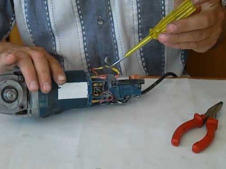
When diagnosing and repairing the electrical part of the grinder, it is most convenient to use a multifunctional tester (abbreviated name is a multimeter). If such a device is not at hand, then a screwdriver with an indicator or a light with two wires is suitable for some checks. During the repair process, the multimeter allows you to measure both the voltage and current values, and the resistance of the motor windings. The indicator and light can only indicate the presence or absence of voltage.
Power failure diagnostics
Perhaps the most common malfunction of a grinder's electrical equipment is a break in the power wires inside the sheath of the power cable. To diagnose and repair such damage, it is enough to disassemble the rear handle of the grinder and check the voltage at the terminals in front of the switch. Another way is to disconnect the cable terminals and use a multimeter to check the resistance of each wire for an open.
Checking the stator and rewinding it
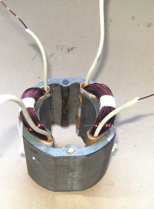
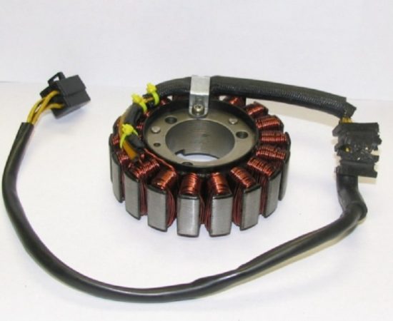
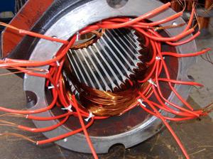
To check the stator of the grinder's electric motor, it is necessary to disconnect both of its windings from the power circuit, and then measure their resistance with a multimeter in the range of 200 ohms. On a serviceable winding, the device will show a resistance of about one ohm, and on a faulty one (with a break) - tens or hundreds of ohms. If the winding fails as a result of a short circuit, then carbon deposits can usually be seen from the inside of the stator housing. It is impossible to check the stator for turn-to-turn closure with a conventional tester - there are special induction devices for this. The only way to repair the stator is to replace or rewind it. The second is possible only with the appropriate qualifications, therefore, most often the stator is simply changed.
Diagnostics of the anchor by the tester
It is necessary to check the anchor of the grinder for both the breakage of the windings and their short circuit to the core. In the first case, the resistance is measured in a circle between two adjacent collector plates located on the rotor shaft. All values should be the same (within one ohm), and a significant difference indicates an open circuit. In the second, the measurement is made between the rotor magnetic circuit and the collector plates. To search for an interturn short circuit, as in the case of the stator, you must use a special device. If a malfunction is found, it is necessary to decide in what way to make the repair: by rewinding the anchor or replacing it with a new one. It is unrealistic to rewind the armature windings on your own without the appropriate skills and equipment, and rewinding in the service will cost almost the same as a new anchor. Therefore, the best repair option is the purchase and independent replacement of the anchor.
Checking the start and control unit
Diagnostics of the electronic components of the grinder is reduced to determining the health of individual units, and repair (if there are no skills in radio engineering) - to their complete replacement. The soft starter can be checked with a pointer ammeter, comparing the current surge with and without it. An oscilloscope is required for accurate diagnostics of the load control unit.Although, in order to understand whether it is serviceable in principle or not, it is enough just to observe the behavior of the grinder in different modes.
Checking carbon brushes
In the process, the carbon brushes are erased and must be replaced when the minimum size is reached. The first sign of a problem with the brushes is an irregular spark ring around the manifold with bursts. Some models have round holes with screw caps for replacement and inspection of brushes. But for most grinders, in order to change them, you have to completely disassemble the body or the rear handle, as in a repair.
Diagnostics of the start button and the speed controller
The most common malfunction in the electrics of a grinder is the failure of the start button, which is most often the result of dust getting into it. You can check the functionality of the button using a multimeter or an indicator screwdriver by measuring the voltage at its output contact. It usually cannot be repaired and is simply replaced with a new one. Determining the malfunction of the speed regulator is even easier: when the wheel rotates, it either changes the number of spindle revolutions or not. If you don't have the skills to repair such devices, then it's easier to buy a new one for a few hundred rubles.
Stages of the stator rewinding procedure
When working, it is important to get a strictly defined number of turns - it should be identical to the number of turns of the old winding. The wire must be wound so that the seal is maximized
The coils are inserted into the stator. From the same material from which the winding for the coils is made, conclusions are drawn. Their ends must be insulated with cambric - tubes made of plastic.
Before installing the coils, it is necessary to check that the groove boxes are symmetrical. They should cover the winding. If this does not happen, when laying the wires of the coils, temporary inserts are installed. This is a simple measure to avoid damage.
The coil is mounted over the groove below the bore. The coil conductors are installed using a special plate. The wires located in the groove must never cross. They need to be laid in the same way, in the same sequence as the winding. Conductors must be installed strictly in parallel.
To perform the next operation, the stator needs to be rotated slightly - only one division. Coils from the same group fit into the groove. After finishing the installation, you need to put interlayer spacers. Screw the leads to the outer contour so that they are parallel to the outer contour. The underside of the coils is mounted in the same way. The operation is repeated until the grooves of this step are filled.
When the winding is finished, the ends can be sleeved. The dimensions of the sleeves depend on the dimensions of the stator. The liner thickness is usually 0.2 mm, but the length must be greater than the dimensions of the launcher. Most often, this value is about 1.5 mm. For the manufacture of the sleeve, special cardboard is used. You need to wrap a film on it (it must be heat-resistant). The entire resulting structure is wrapped with tape. The coils with sleeves must be installed in the stator grooves. After that, you can check if the anchor is moving correctly. The coil is completely ready. It remains only to wrap it with keeper tape, and cover it with a layer of varnish on top. After the varnish has dried, the device is completely ready for use.
When it comes to rewinding the stator, in the overwhelming majority of cases, it means repairing the tool. As an example of the execution of the indicated process, we can cite the rewinding of the stator on the grinder.
The indicated process of replacing windings in one of the parts of an electric motor can be carried out in domestic conditions. This can be explained by a complete repetition of the burned out winding.That is, exactly the same conductor is selected, with exactly the same insulation.
Replacing the anchor yourself at home
Practice shows that if it is decided to replace the grinder's armature, then it is best to change it together with the support bearings and the engine cooling impeller.
Replacement will require:
- New LBM anchor. Must match your model. Interchange with other models is unacceptable.
- Screwdrivers, wrenches.
- Soft brush and cloth for cleaning the mechanism.
How to remove the anchor
Replacing the anchor begins with disassembling the grinder. The following steps are taken:
- The brush assemblies are unscrewed with a screwdriver on both sides. The brushes are removed.
- Unscrew 4 screws securing the gearbox housing.
- The gear cover is carefully opened and removed to gain access to the inside of the gear mechanism.
- The retaining ring is removed, which fixes the small gear to the anchor.
- The anchor retainer is released from the fastening, the anchor is removed along with a small gear and a bearing.
- The gear wheel, bearing and armature fixing disc are removed, wiped with a rag. The bearing is removed with a special puller.
Video: replacing bearings on a grinder
How to anchor in place
To install a new grinder anchor in place, take a new part, and then assemble the tool in the reverse order. The sequence of actions is as follows:
- A fixing disc is installed on the armature shaft.
- The bearing is installed by pressing.
- The small gear is pushed on and secured with a retaining ring.
- The armature is wound into the gearbox housing, the docking holes are aligned.
- The gearbox mounting bolts are tightened.
- The anchor with a gearbox is inserted into the grinder body and fixed.
- The brushes are deposited in their places, closed with lids.
After completing these steps, the grinder is ready to work. The anchor has been replaced.
Video: how to check a grinder
The ancient Sufi wisdom says: “Smart is the person who is able to get out of a difficult situation with dignity. But he is wise who does not get into such a situation. " Observing the rules for the operation of household appliances, avoiding overheating of the motor, you can avoid breakdowns and troubles in the operation of the grinder. Keeping and storing the tool clean and dry will prevent its mechanisms from contamination and oxidation of current-carrying elements. Timely maintenance of the tool is guaranteed to save you from unpleasant surprises during work.
Features of checking the grinder's anchor with a tester
The diagnostic procedure will help pinpoint the problem of the motor part. The device, which is available in the arsenal of tools of many amateur electricians, will allow you to check the grinder's anchor with a tester. With the help of the tester, you can check not only the anchors of the grinders, but also the stator windings of other electric motors. In the video below, you can see one of these homemade measuring instruments in action.
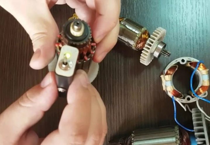
When the tester is plugged in, the indicator lights up. A red light without the attachment of a technical device to the anchor means that the device is ready to be checked. The working active surface of the measuring device has two points of contact with the investigated one. One of them is the generator coil, the second is the coil of communication curls. When checking the grinder's armature with a tester, it is necessary to substitute this surface to the investigated groove. Make sure that the sensors do not extend beyond the armature plates on both sides at the same time.
If the electrical part is in good order or rewound, then during its check with a tester opposite each of the grooves, the indicator will glow green. If there is a malfunction in the armature of the angle grinder, in particular, a turn-to-turn circuit, a red light will be indicated on the indicator of the device in the place of its localization.Be careful when performing the diagnostic procedure in order to achieve correct contact of the surfaces when checking the grinder's armature with a tester. Mechanical damage should not be excluded from the reasons for the failure of the angle grinder, which can be noticed visually without ringing with a multimeter. They can be both significant and small. You may notice breakage on inspection by disassembling the grinder. It is necessary to diagnose such malfunctions before checking the armature for interturn closure.
If you do not have experience in disassembling a power tool or preparing to work with measuring instruments for ringing the armature with a multimeter and are not sure of your own strength, you should not interfere with the design of the grinder. Do not experiment to avoid damaging the angle grinder. In this case, in order to find the cause of the breakdown of the power tool and check the grinder's armature with a tester, it is better to contact a service center or qualified locksmiths who specialize in equipment repair.

