Usage
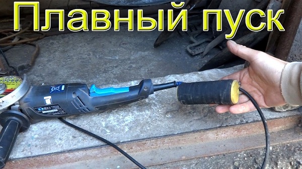
There are a number of recommendations for the correct use of a grinder with an electronic unit. When starting the tool, let it accelerate to the set speed, do not rush to cut anything. After turning off, restart it after a few seconds so that the capacitors in the circuit have time to discharge, then the restart will be smooth. You can adjust the speed while the grinder is in operation by slowly turning the variable resistor knob.
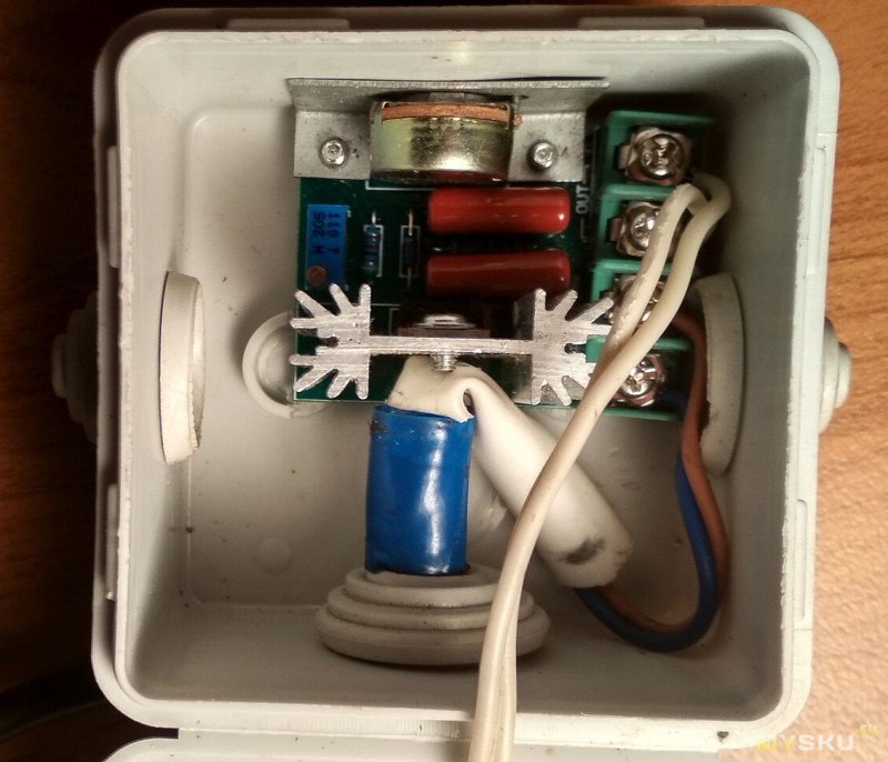
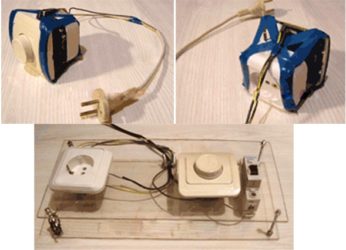
A grinder without a speed regulator is good because you can make a universal speed regulator yourself for any power tool without serious costs. The electronic unit, mounted in a separate box, and not in the case of the grinder, can be used for a drill, drill, circular saw. For any tool with a brushed motor. Of course, it is more convenient when the regulator knob is on the instrument, and you do not need to move anywhere and bend over to turn it. But it's up to you to decide. It's a matter of taste.
If there is an old grinder among your tools, do not rush to get rid of it. Using a simple wiring diagram, the tool can be improved by adding an option for adjusting the speed. Due to the usual control device, which you can create with your own hands within a few hours, the functions of the tool will significantly expand. By reducing the number of rotations per unit of time, the angle grinder can be used as a sharpening and grinding unit for different types of materials. There will be additional opportunities for using auxiliary equipment and attachments.
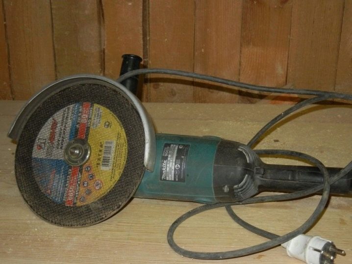
Why control the speed of the disc
If the grinder is used for cutting and cutting tiles, natural stone products, the high speed of rotation of the tool literally kills the power tool. In addition, with such processing, small particles begin to crumble out of the material. This significantly impairs the quality and appearance of the tile or stone surface. With the function of selecting the required revolutions, the processing proceeds without a hitch. And the electric tool itself is completely protected from damage.
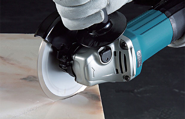
When cutting tiles and stone products, the grinder works at a very high rotation speed
Also, the rotation speed is important when working with metal products. For example, aluminum or tin blanks should be cut at minimum speed. Thick and hard metal, on the other hand, is processed at high speeds. Polishing and grinding work using angle grinders is completely impossible to perform efficiently if the saw does not allow you to select the desired speed. You will simply ruin the surface to be treated. Try sanding wood or car body paint at high rotational speed and you'll know what this is about.
As you can see, the refinement of the angle grinder makes the device much more functional. It becomes possible to work with any soft materials and delicate surfaces. And most importantly, the Bulgarian becomes almost eternal. It will function for more than a dozen years!
Subtleties of work
If the regulator is assembled correctly and adjusted, then it will be convenient to turn on the tool at low speeds, when there is no jerk. During operation, especially considering the increased danger of angle grinders, it is necessary to make sure that accidental impact on the regulator handle is impossible.
This is especially important if the regulator is built into the cord, not far from the body of the grinder itself.
If before that the machine did not have a regulator, then it must be borne in mind that this regulator will strive to maintain a speed close to idle under load, so it is not necessary to especially accelerate the grinder under a heavy load. When the resistance of the material being processed slows down the disc, the voltage across the current sensor rises due to the increase in current, and the voltage across the motor drops slightly. The microcircuit reacts to this by changing the angle (the moment the triac is unlocked) in the direction of increasing the power.
In case of too much current, the protection is triggered and the angle changes in the direction of decreasing power. So, you may have to choose R9 through experiments, within small limits, changing the design resistance.
Principle of operation
For assembly, it is best to choose a thyristor converter, it will allow you to change the operating mode without significant losses.
In addition, thanks to it, such functions will be configured as:
- Acceleration-deceleration.
- Strict regulation of characteristics.
- Switch to reverse movement.

In addition, it has pulse-phase control. Which, allows not to lose the rotor torque without increasing the losses on the reactive characteristic.

The governor circuit will consist of the following key components:
- Controlled signal rectifier.
- Regulation block.
- Feedback system.
- Network power regulator.

How to connect the device to a grinder, options
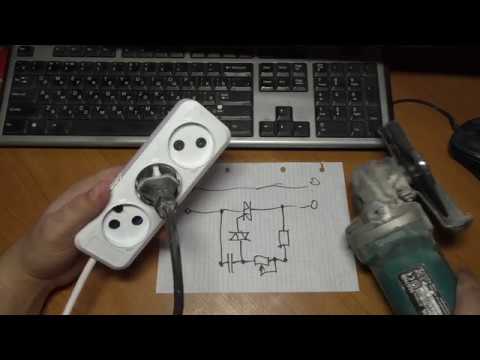
The connection of the regulator depends on which type of device is selected. If a simple circuit is used, it is enough to mount it in the mains supply channel of the power tool.
Installing a homemade board
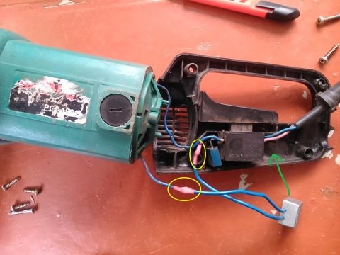
There are no ready-made installation recipes. Anyone who decides to equip the angle grinder with a regulator disposes it according to his goals and the model of the instrument. Someone inserts the device into the handle of the holder, someone into a special additional box on the body.
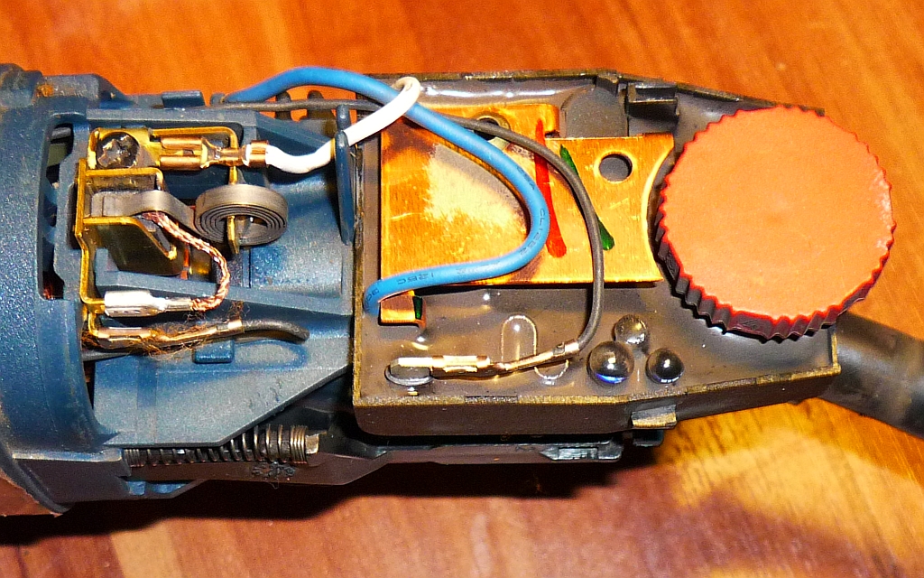
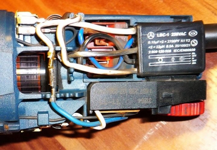
In different models, the space inside the grinder body may be different. Some have enough free space to install a control unit. In others, you have to bring it to the surface and fix it in a different way. But the trick is that, as a rule, there is always a certain cavity in the back of the instrument. It is designed for air circulation and cooling.
Cavity in the back of the device
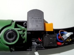
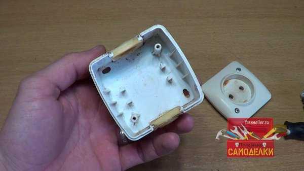
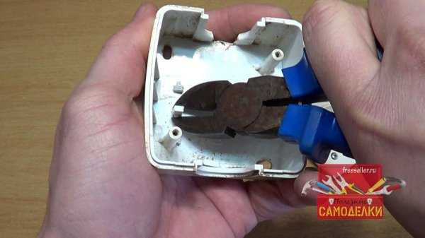
Usually this is where the factory speed regulator is located. A DIY scheme can be placed in this space. To prevent the regulator from burning out, the thyristors should be installed on the radiator.
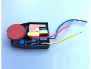
Features of mounting a finished block
When buying and installing a factory regulator inside the grinder, most often you have to modify the body - cut a hole in it to output the adjusting wheel. However, this can adversely affect the rigidity of the casing. Therefore, it is preferable to install the device outside.
The adjusting wheel changes the speed
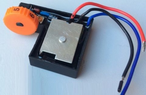
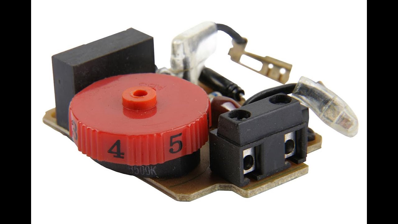
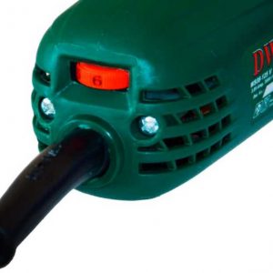
The numbers on the adjusting wheel indicate the number of spindle revolutions. The meaning is not absolute, but conditional. "1" - minimum speed, "9" - maximum. The rest of the numbers are for guidance when regulating. The location of the wheel on the body is different. For example, on the angle grinder Bosch PWS 1300–125 CE, Wortex AG 1213–1 E or Watt WWS-900, it is located at the base of the handle. In other models, such as the Makita 9565 CVL, the adjusting wheel is located at the end of the casing.
The connection diagram of the regulator to the grinder is not complicated, but sometimes it is not so easy to stretch the cables to the button, which is located on the other end of the device case. The problem can be solved by selecting the optimal wire cross-section or by bringing it to the surface of the casing.
The regulator is connected according to the diagram
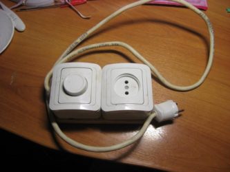
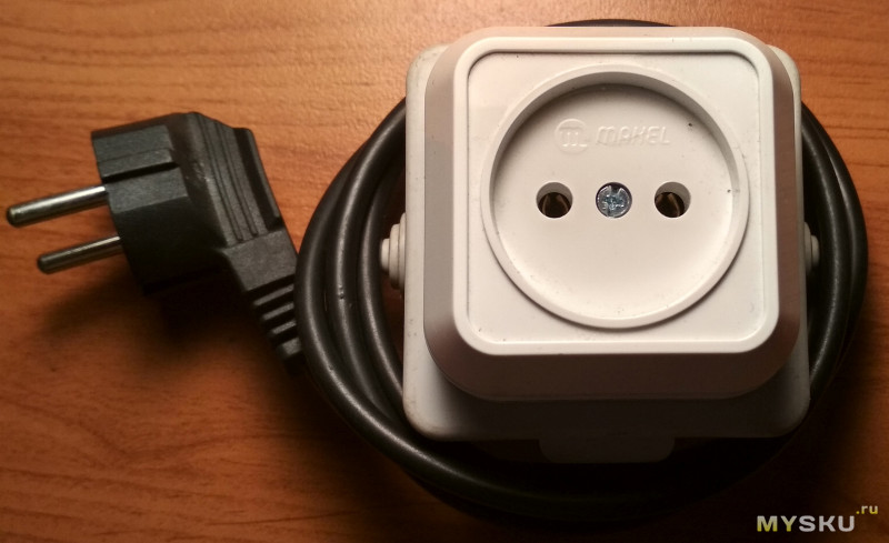
A good option is to install the regulator on the surface of the device or fasten it to a power cable.Not always everything works out on the first try, sometimes the device has to be tested, and then some adjustments are made. And this is easier to do when access to its elements is open.
 Attachment to the power cord
Device manual
The basic rule when operating a grinder with a homemade speed controller is to observe the work and rest mode. The fact is that the engine operating at the "regulated" voltage is especially hot
When grinding at reduced speeds, it is important to take frequent breaks so that the collector windings do not burn out.
It is also highly discouraged to turn on the tool if the speed controller is set to a minimum - the undervoltage is not enough to rotate the rotor, the collector lamellas will remain in short-circuit mode, and the windings will start to overheat. Unscrew the variable resistor to the maximum, then, turning on the angle grinder, reduce the speed to the desired value.
In addition, it should be understood that the speed control on the grinder is based on the principle of a water tap. The device does not increase the number of revolutions, it can only lower them. It follows from this that if the maximum passport speed is 3000 rpm, then when the speed controller is connected, the grinder will operate in a range lower than the maximum speed.
Video: homemade angle grinder
Equipping the grinder with an engine speed control circuit will increase the efficiency of using the device. and will expand its functional range. It will also save the technological resource of the grinding machine and increase its service life.
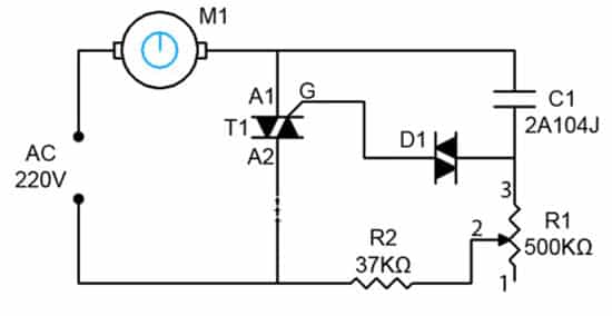
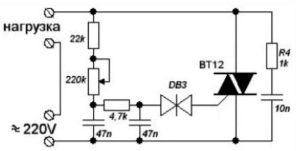
Typical speed regulator circuit

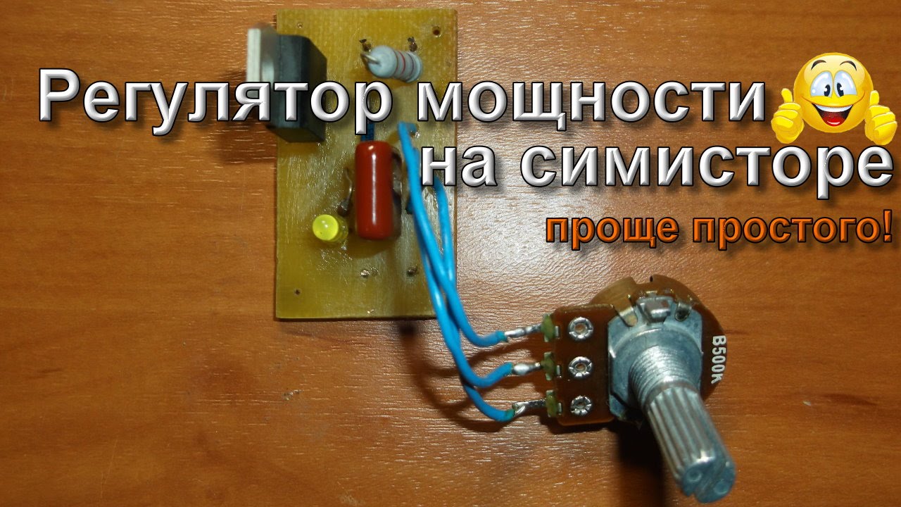
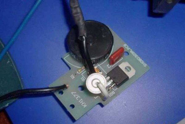
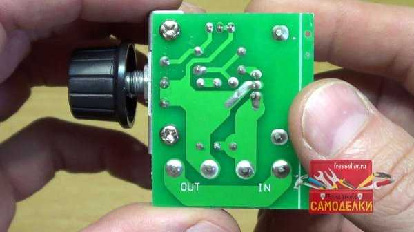
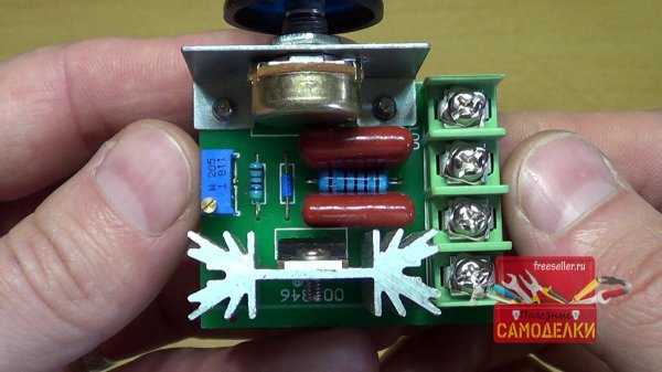
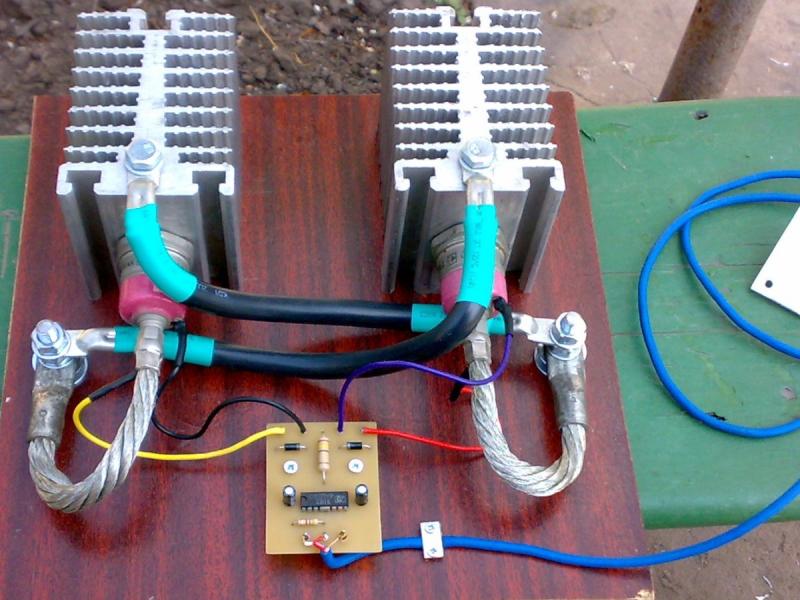
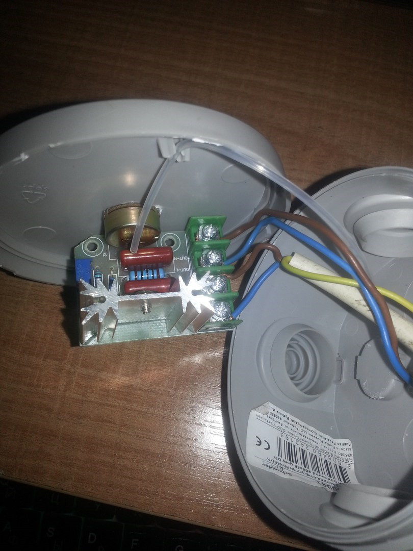
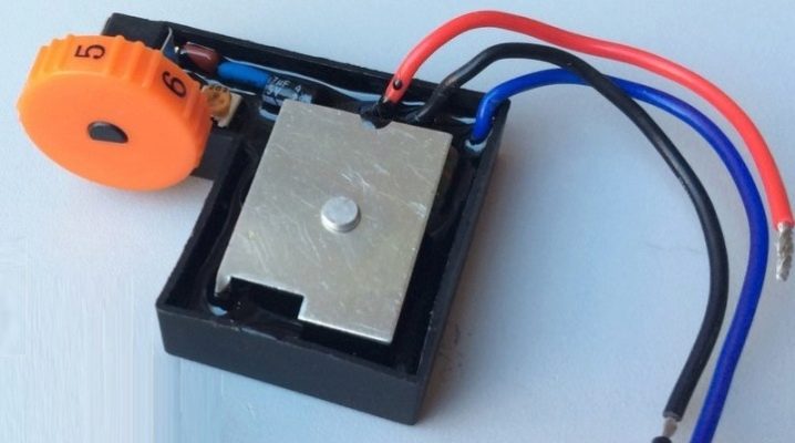
This is how the governor board assembly looks like.
The engine speed regulator is not just a variable resistor that pulls down the voltage. An electronic control of the magnitude of the current is required, otherwise, with a drop in speed, the power will proportionally decrease, and, accordingly, the torque. In the end, a critically low voltage value will come, when, with the slightest resistance of the disk, the electric motor simply cannot turn the shaft. Therefore, even the simplest regulator must be calculated and executed in the form of a well-developed circuit.

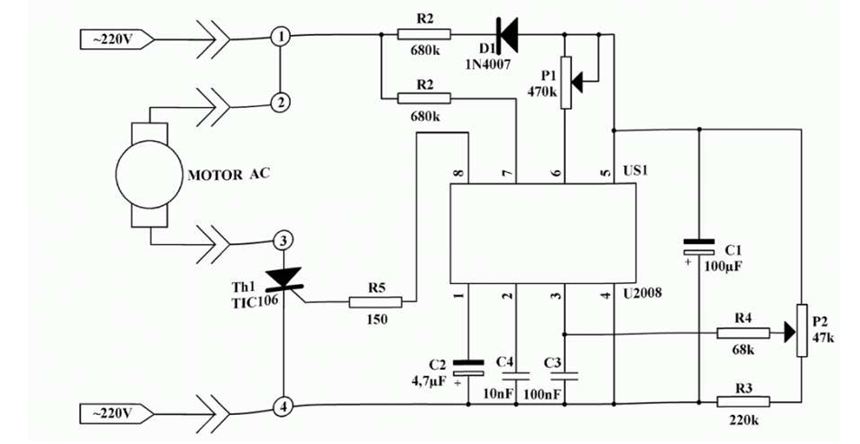
And more advanced (and, accordingly, expensive) models are equipped with regulators based on an integrated circuit.

Integrated circuit of the regulator. (most advanced option)
If we consider the electrical circuit of the grinder in principle, then it consists of a speed controller and a soft start module. Power tools equipped with advanced electronic systems are significantly more expensive than their simple counterparts. Therefore, not every home craftsman is able to purchase such a model. And without these electronic blocks, only the winding of the electric motor and the power button will remain.
The reliability of modern electronic components of angle grinders exceeds the resource of the motor windings, so you should not be afraid of purchasing a power tool equipped with such devices. The only limit can be the price of the product. Moreover, users of inexpensive models without a regulator sooner or later come to install it on their own. The block can be purchased ready-made or made by yourself.
Why do you need to adjust the speed on the angle grinder
Any grinder is structurally "sharpened" to work only with a cutting or grinding wheel of a certain diameter. In total, there are six most common diameters in the range from 115 to 300 mm, which correspond to six groups of spindle speeds at idle speed. For example, grinders with Ø125 mm wheels have a rotational speed of about 11 ÷ 12 thousand rpm, and with circles Ø150 mm - 9 ÷ 10 thousand rpm. Such values of the spindle speed are due to the fact that cutting discs are designed for high-performance processing of hard materials (metal, stone, ceramics) at cutting speeds up to 80 m / s.
However, when cutting and especially grinding soft and tough materials, completely different cutting parameters are required and, accordingly, the use of a tool with a speed controller. And this applies not only to wood and plastics, but also to steels, titanium and aluminum alloys. For example, processing of plastics and soft types of wood occurs at cutting speeds from 8 to 12 m / s, grinding of titanium and stainless steel alloys - within 15 ÷ 20 m / s, and even ordinary steel is ground at no more than 30 m / s. Therefore, the rotational speed of grinders for grinders should be several times less than the passport one. It should be noted that in the bulk of the angle grinder speed controllers are inherently power controllers supplied to the electric motor of the grinder. That is, a decrease in the number of revolutions is achieved by reducing the power of the source by up to 15% of the nominal. But for grinding and cutting soft materials, this does not really matter, since in this case, a small amount of power is required initially.
Speed controller and soft start - what are you needed for?
In modern grinders, two important functions are used that increase the reliability and safety of the tool:
- speed regulator - a device designed to change the number of engine revolutions in various operating modes;
- soft start - a scheme that provides a slow increase in engine speed from zero to maximum when the device is turned on.
They are used in electromechanical tools, in the design of which a collector motor is used. Contributes to the reduction of wear on the mechanical part of the unit during start-up. They reduce the load on the electrical elements of the mechanism, starting them up gradually.
When the power is turned on, there is an abrupt transition from the rest state to the rotation of the disk at a speed of 2.5-10 thousand revolutions per minute. Those who have worked with a grinder are well aware of the feeling that the machine is simply "being pulled out of hand". It is at this moment that the overwhelming number of breakdowns associated with the mechanical part of the unit occurs.
The stator and rotor windings are equally stressed. The collector motor starts in short-circuit mode, the electromotive force is already pushing the shaft forward, but the inertia still does not allow it to rotate. There is a jump in the starting current in the coils of the electric motor. And although structurally they are designed for such work, sooner or later a moment comes (for example, with a voltage surge in the network) when the insulation of the winding does not withstand and an interturn short circuit occurs.
When you include soft start circuits and changes in engine speed into the electrical circuit of the instrument, all of the above problems automatically disappear. Among other things, the problem of voltage "dip" in the common network at the moment of starting the hand tool is solved. This means that the refrigerator, TV or computer will not be exposed to the danger of "burnout". And the safety devices on the meter will not work and turn off the current in the house or apartment.
The soft start scheme is used in grinders of medium and high price categories, the speed control unit is mainly used in professional LBM models.
Additional wiring diagrams increase the cost of the tool, but increase the service life and the level of safety during operation.
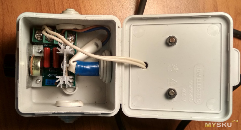
Do-it-yourself photo of the speed controller


We also recommend viewing:
- Do-it-yourself engine oil change
- DIY engine repair
- DIY bumper
- DIY car painting
- DIY car polishing
- DIY headlight polishing
- Replacing thresholds with your own hands
- Do-it-yourself carburetor adjustment
- How to replace candles
- DIY trunk
- Do-it-yourself windshield replacement
- DIY bearing replacement
- Do-it-yourself dry cleaning of the salon
- DIY body repair
- DIY rear view camera
- Do-it-yourself nozzle rinsing
- DIY trailer
- DIY clutch replacement
- DIY starter repair
- DIY automatic transmission repair
- DIY headlight adjustment
- DIY mini tractor
- DIY steering rack repair
- Do-it-yourself car soundproofing
- DIY vase tuning
- DIY generator repair
Screwdriver speed regulator
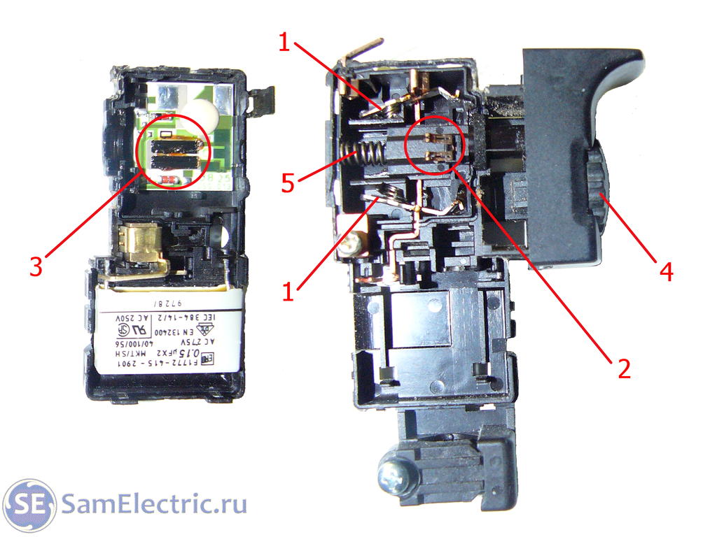
The electric screwdriver works either from a 220 V network or from a rechargeable battery. Its power depends on the voltage of the battery. The rotational speed of the screwdriver starts at 15,000 rpm. In addition, the mains-powered screwdriver has 2 speeds: a slower one for screwing in, a higher one for drilling. There is a speed regulator inside the power button. The fairly miniature size of this tool assembly is achieved using microfilm technology. Its main part is a triac. The principle of operation of the regulator is as follows:
- When the button is turned on, an alternating current with a sinusoidal phase is supplied to the control electrode of the triac.
- The triac opens, the current begins to flow through the load.
The triac response time depends on the amplitude of the control voltage. The larger the amplitude, the earlier the triac is triggered. The magnitude of the amplitude is set using a variable resistor connected to the start button. The button connection diagram is different in different models. A condenser can be connected to the speed controller.
Often, in the current economic conditions, the buyer cannot always afford a full-fledged expensive screwdriver from well-known companies. Cheaper models may not have this feature. But this is not a reason to despair. The speed controller can be assembled by yourself, which we will talk about below.
The screwdriver speed controller is assembled on the basis of a PWM controller and a key multichannel field-effect transistor. The resistor controls the operation of this unit of the instrument. Its position depends on the pressure on the start button of the screwdriver.
The direction of rotation of the working body is changed by changing the poles of the voltage that is supplied to the motor brushes. Instrumentally, this is done with the help of changeover contacts actuated by the reverse lever.
It is possible to assemble such a regulator with your own hands. We will consider how to do this below.
A diagram of the elements that make up the speed regulator is shown in the figure below.
Scheme
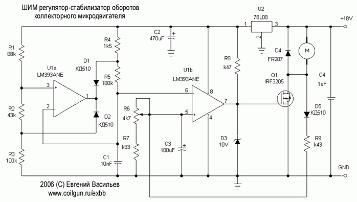
In this case, an LM 393 dual comparator microcircuit is used. Here, the first comparator works as a sawtooth voltage generator, the second is PWM. The control signal for PWM is the voltage drop across the motor contacts. To put it simply, in the diagram, the electric motor looks like an active and inductive resistance, connected in series with each other. When the load changes, the ratio of these resistances changes, respectively, the regulator controls this and changes the PWM filling, thereby stabilizing the speed.
An electronic transformer should be used as a power supply for PWM. It is a half-bridge voltage converter from 220 to 12 V, which is used to power halogen lighting lamps. Its dimensions are comparable to those of a matchbox. The price ranges from 2–3 USD. e. It is necessary to add a rectifier to the output (these are four diodes, for example, KD 213), as well as a capacitor with a capacity of several thousand microfarads per 25 volts. All this will constitute a switching power supply with constant voltage at the output.
Separately, it is worth talking about the manufacture of a printed circuit board for the regulator. To make it, you need a sheet of photographic paper, a laser printer. First, you need to print the pattern on photographic paper using a laser printer, then transfer it to the board blank using a heated iron.The blank of the board with the stuck paper is placed in a container and placed under a stream of hot water. This is done so that the gelatinous layer of the photographic paper swells, and it peels off the board. The remaining pattern on the board is etched with ferric chloride.
Self-creation of a regulator
How to make your own regulator yourself? The desire to attach an ordinary electronic device designed to change the electrical power (dimmer) ends in nothing. First of all, the grinder dimmer is designed for a different load. Also, the dimmer is not combined with the control of the electric motor winding. Therefore, you need to install a separate circuit. You also need to figure out where it will be located inside the grinder's body.
A simple semiconductor device (thyristor regulator) can be built by hand. For this procedure, 5 radioelements will be needed. You can buy radio elements on the radio market. Due to its compactness, you can safely place the prepared circuit in the grinder without damaging the ergonomics and reliability. However, the preservation of torque does not occur when the speed of the grinder is reduced. This option is best suited for processing soft metals, as well as tin, which has a small thickness.
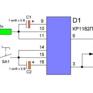 If you are processing stone, then you need to install a disc that has a size of 180 millimeters. Next, you need to create a more complicated regulator circuit. In this scheme, the control module will be the KR1182PM1 microcircuit. This circuit has control over the amperage at different rpm, and also minimizes the loss of torque when the rpm is reduced. With this scheme, engine operation is increased.
If the angle grinder is used as a circular, then you need to equip the grinder with a connection point. Thanks to such a point, a connection is made, and the speed can be adjusted remotely. You will have a great homemade speed governor.
It doesn't depend on how you made the adjuster that it is a must-have component of an angle grinder, which makes the work possibilities wider and allows you to comfortably use this construction tool. Also, after installing the regulator, it is necessary to conduct a test run of the angle grinder to check: whether the construction tool is torn out of the hands. You can make an external speed controller for a grinder with your own hands.
How to assemble a regulator with your own hands?
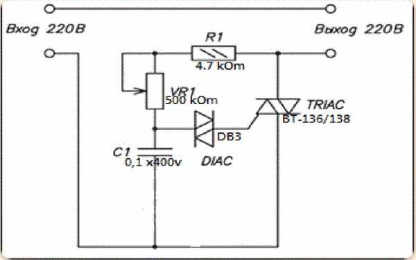
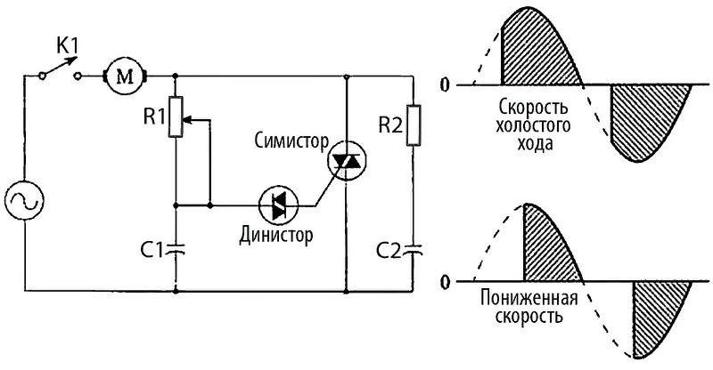
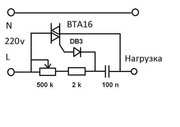
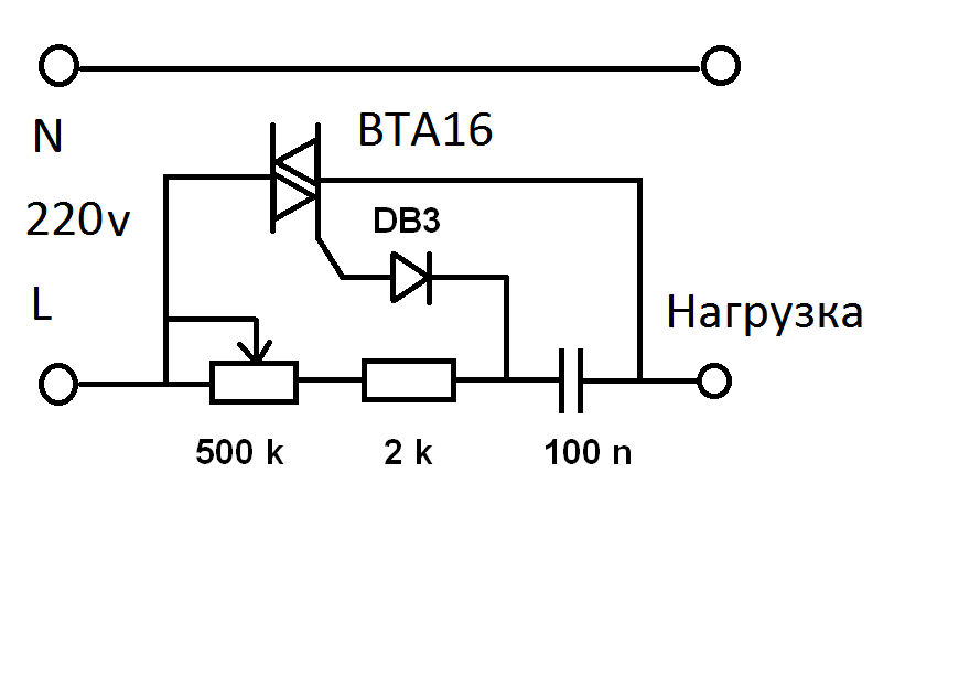
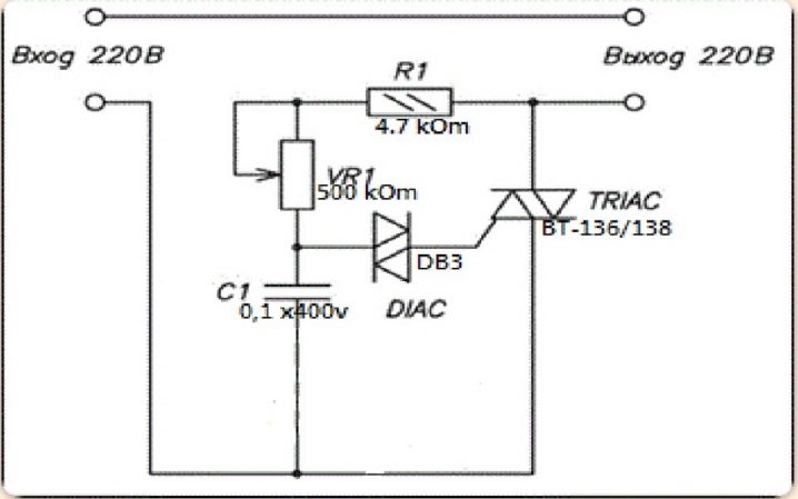
A simplified and rather reliable frequency converter for angle grinders is constructed with your own hands from available electrical parts. Below is a diagram showing all the required components for mounting on a printed circuit board of the device of interest to us.
So, we need:
- symmetrical triode thyristor (or triac, triac) DIAC (DB3);
- resistor (resistance) R1 (its parameters should be 4.7 kΩ);
- additional triac VT136 / 138 (TRIAC);
- capacitor C1 (400 V, 0.1 μF);
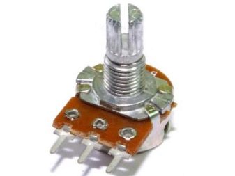
- additional resistance VR1 for 500 kOhm.

A similar scheme operates according to the following method.
- The charging time of the capacitor is modified by an auxiliary resistor (it is called the trimmer). When voltage is applied to the circuit, the triacs are in the closed position, and a zero voltage value is observed at the output.
- In the process of charging the capacitor, an increase in voltage is noted on it, which leads to the opening of the DB3 triac. As a result, the voltage falls on VT136 / 138. This thyristor element also opens up, and an electric current flows through it.
- After that, the symmetrical components are closed again and remain in a similar status until the capacitor is completely recharged in the opposite direction.
- Ultimately, at the conclusion, we acquire a deterministic signal of finite energy that is complex in its configuration.Its exact range is determined by the period of performance of the functions of the circuit capacitor - auxiliary resistance - resistance R1.
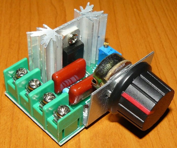
Triacs are usually located on a printed circuit board. It is easy to create it from PCB (multilayer extruded plastic is used, consisting of heat-insulating fiber and foil). Individual craftsmen cut the board with a cutter. It is practiced to place the circuit elements using the hinged mounting method. Triystres are mounted only on an aluminum or copper heat exchanger. It plays the role of a good heat sink.
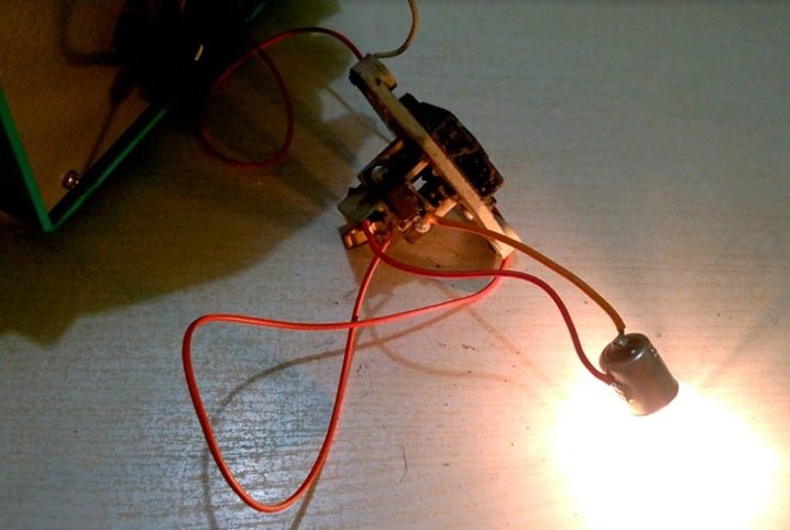
The test of the assembled device is carried out using an ordinary 40-60 W incandescent lamp. Connect it to the circuit and start to regulate the glow power. If the brightness changes, then you have done everything correctly. Now you can start installing the regulator in the shell of the angle grinder. This is not very easy to do, since it is necessary to ensure that the accessory does not interfere with you when using the angle grinder.
You will need to calculate the installation location of the homemade control device yourself, in accordance with the design features of the grinder. The installation of the circuit is performed:
- in an additional box mounted on the unit body;
- into the handle of the holder;
- into a small empty niche (it is designed to cool and circulate air masses) in the rear area of the angle grinder.
The very connection of the circuit to the device is made by integrating it into the electric supply channel of the angle grinder. You probably won't have any difficulties with this.

