How to choose a generator for a walk-behind tractor correctly?
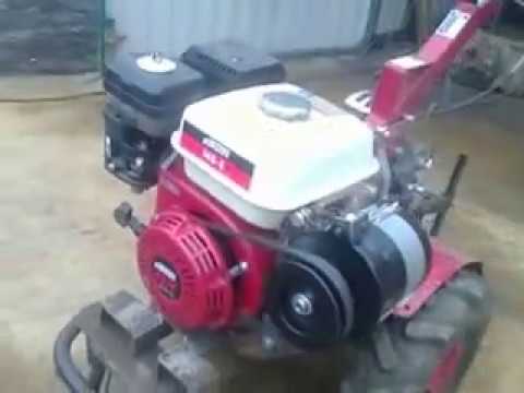
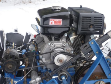
The standard and most versatile option is considered to be 12 volts, and you can choose either a specially produced by the manufacturer as an additional accessory for a certain model of a walk-behind tractor, or any other, including one that is used with another tractor or car. The main thing is that its power is greater than the load installed as a whole, since it will need to work without voltage surges, even if absolutely all electrical appliances are involved at the same time. For the rest, the desired characteristics are calculated based on the planned scope of work, financial availability and ease of maintenance, as well as the repair of the device.
It is interesting: Types of milling cutters for a walk-behind tractor and other equipment for tillage: we outline the main thing
Possible problems and solutions
A serious breakdown, of course, cannot be solved without contacting a service center or professional repairmen. But with the current simple ones, everyone can cope independently. Among the most common user complaints, the following should be noted:

For the rest, it is obvious that the installation of a walk-behind tractor generator is in no way difficult. Moreover, in this case, there is a chance to significantly save on it, as well as to remain in complete confidence that it was made really qualitatively, with strict adherence to all norms and recommendations. Of course, this process will be difficult for beginners without experience with an electrician, but, what pleases, the acquired skill will be useful in the future.
Generator device
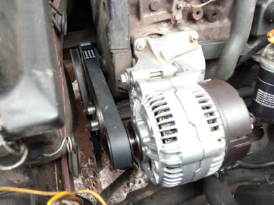
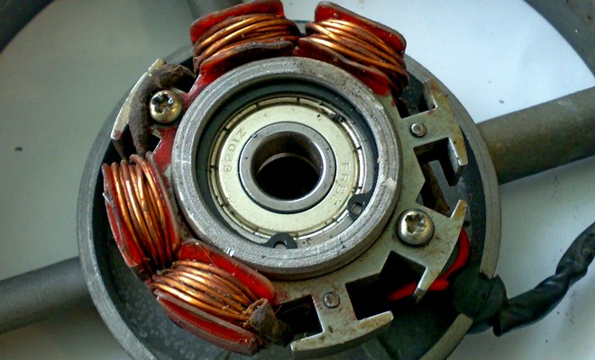
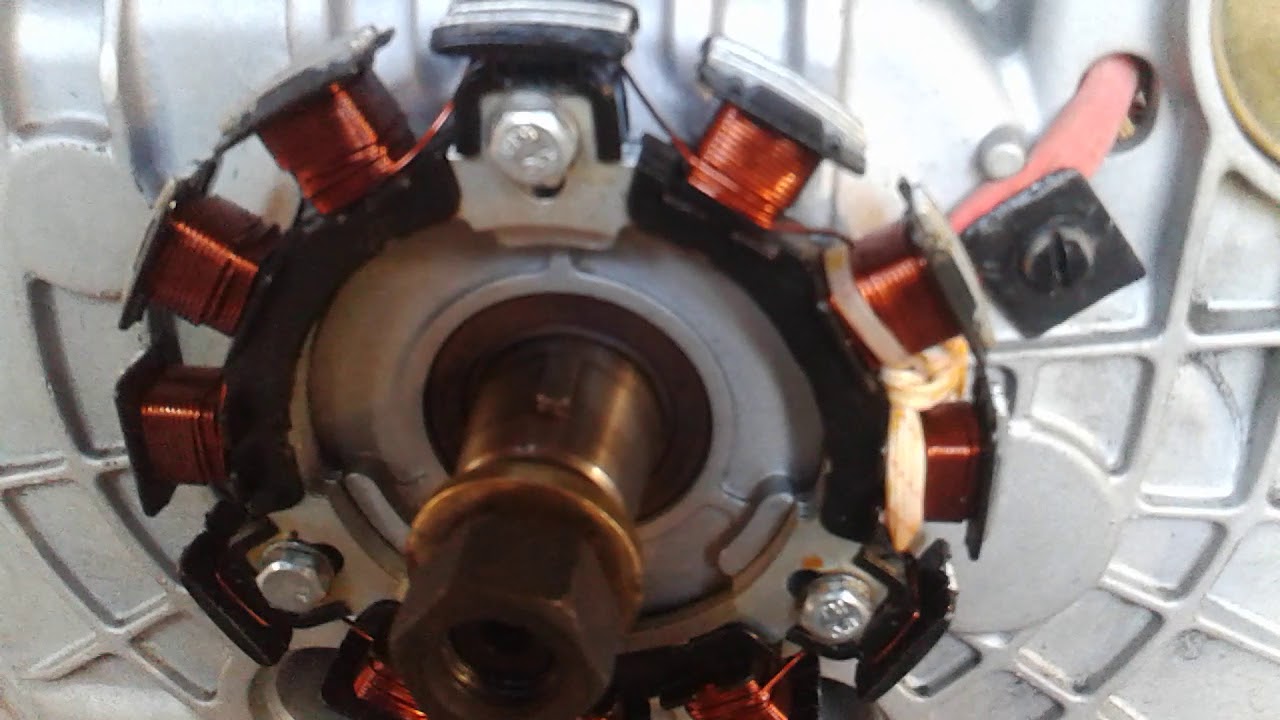
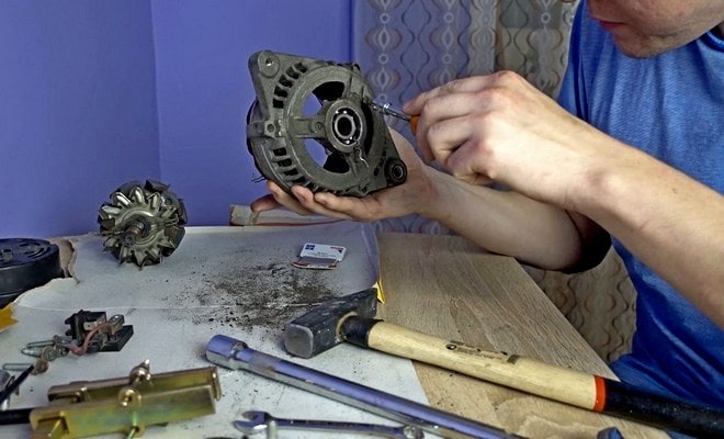
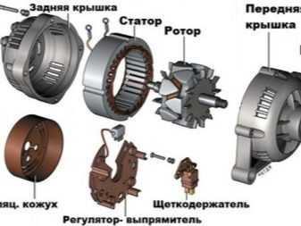
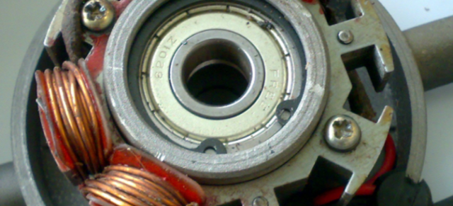
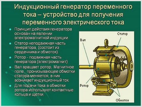
The device of an automobile generator implies the presence of its own rectifier and a regulating circuit. The generating part of the generator with the help of a stationary winding (stator) generates a three-phase alternating current, which is then rectified by a series of six large diodes and already a direct current charges the battery. The alternating current is induced by the rotating magnetic field of the winding (around the field winding or rotor). Further, the current is fed through the brushes and slip rings to the electronic circuit.
Generator device: 1. Nut. 2. Washer. 3.Pulley. 4. Front cover. 5.Distance ring. 6.Rotor. 7.Stator. 8.Rear cover. 9.Casing. 10.Gasket. 11. Protective sleeve. 12. Rectifier unit with capacitor. 13. Brush holder with voltage regulator.
The generator is located at the front of the car's engine and is started using the crankshaft. The connection diagram and the principle of operation of the car generator are the same for any car. There are, of course, some differences, but they are usually related to the quality of the manufactured product, the power and the layout of the units in the motor. All modern cars are equipped with alternating current generator sets, which include not only the generator itself, but also the voltage regulator. The regulator equally distributes the current in the excitation winding, it is due to this that the power of the generator set itself fluctuates at the moment when the voltage at the power output terminals remains unchanged.
Newer vehicles are most often equipped with an electronic unit on the voltage regulator, so the on-board computer can monitor the amount of load on the generator set. In turn, on hybrid vehicles, the generator performs the work of a starter-generator; a similar scheme is used in other designs of the stop-start system.
The principle of operation of the auto generator
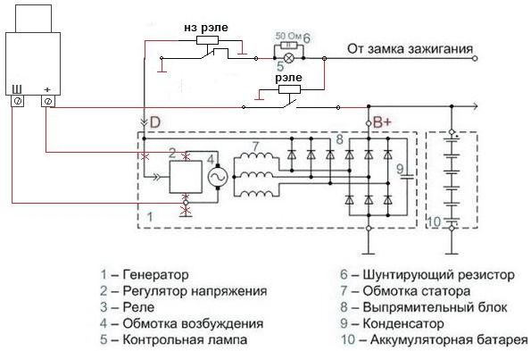
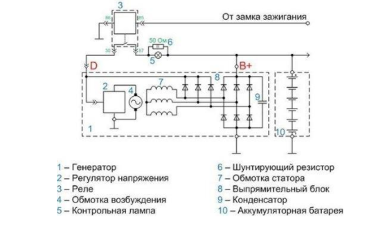
Wiring diagram for a VAZ 2110-2115 generator
The alternator connection diagram includes the following components:
- Battery.
- Generator.
- Fuse box.
- Ignition.
- Dashboard.
- Rectifier unit and additional diodes.
The principle of operation is quite simple, when the ignition is turned on, plus through the ignition switch goes through the fuse box, a light bulb, a diode bridge and goes through a resistor to a minus. When the light on the dashboard lights up, then the plus goes to the generator (to the excitation winding), then, during the engine start-up, the pulley starts to rotate, the armature also rotates, due to electromagnetic induction, an electromotive force is generated and an alternating current appears.
The most dangerous for the generator is the closure of the heat sink plates connected to the "mass" and the "+" terminal of the generator by accidentally falling between them metal objects or conductive bridges formed by pollution.
Further, the diode passes plus into the rectifier unit through the sinusoid to the left shoulder, and minus to the right. Additional diodes on the light bulb cut off the minuses and only pluses are obtained, then it goes to the dashboard assembly, and the diode that it stands there only passes the minus, as a result, the light goes out and the plus then goes through the resistor and goes to minus.
The principle of operation of a car constant generator can be explained as follows: a small direct current begins to flow through the excitation winding, which is regulated by the control unit and maintained at a level of just over 14 V. Most generators in a car are capable of generating at least 45 amperes. The generator runs at 3000 rpm and above - if you look at the ratio of the sizes of fan belts to pulleys, it will be two or three to one in relation to the frequency of the engine.
To avoid this, the plates and other parts of the generator rectifier are partially or completely covered with an insulating layer. In the monolithic structure of the rectifier unit, the heat sinks are united mainly by circuit boards made of insulating material, reinforced with connecting bars.
Next, consider the connection diagram of a car generator using the example of a VAZ-2107 car.
Difference between single and three-phase connection
All connections, whether in a single-phase or in a three-phase network, are completely identical, with the exception of the number of power wires. The only important nuance concerns the so-called control phase - if the starter is connected to the network, then its main contacts connect and disconnect the power wires from the network, and the power for the electromagnetic coil must also be taken from somewhere.
There are no problems in a single-phase network - there is only one phase and such a question simply does not exist, and in a three-phase network everything is somewhat more complicated - there are L1, L2 and L3. Without going into technical details, there is only one answer - for the control circuits, you can use any of the phases, but only one. That is, if the KM1 coil is powered from the L3 phase, then the control of the rest of the starters, the "Start" and "Stop" buttons must also be "suspended" only on it. This is not difficult to do - just note what color the wire is at the desired phase, and if the cable has single-color cores, then stick or draw markers on them.
Do-it-yourself gas generator assembly
To create 220 do-it-yourself electric generators at home for use in a domestic environment, it is necessary to perform a number of activities. To begin with, a diagram is drawn up and, according to it, they are determined with the details and assembly order.
List of main parts
To assemble a 220 V electric generator with your own hands, you need to select in advance all the main parts of which it consists.
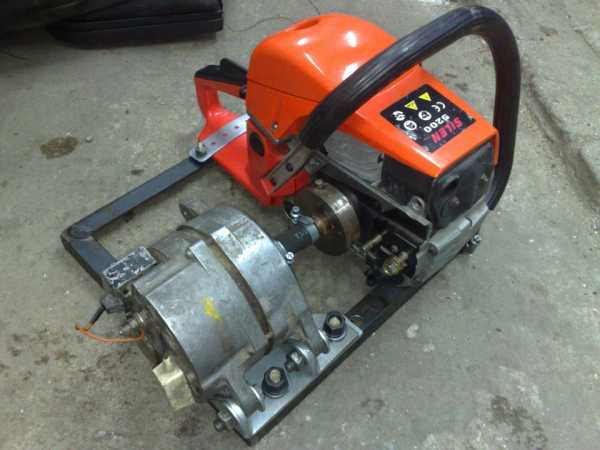
- It is very rare to find a 220 volt generator without an engine. It can be assembled by yourself. But in this case, the whole process will take a lot of time.To shorten the generator manufacturing procedure, the engine can be borrowed from failed equipment. The best options are engines from washing machines, pumping stations, walk-behind tractors, chainsaws. For more powerful ones, you can remove the car engine.
- Electric starter. It is advisable to use a finished part that has a winding.
- Electrical wires and insulating tape.
- To achieve the stability of the power supply, it is necessary to use transformer or rectifier structures. This is relevant in cases where the result is electricity with different capacities. Using a transformer, you can increase or decrease the power.
Assembly principle
After all the components are found and prepared, they proceed directly to the assembly of a homemade 220 V alternator. The principle consists of several stages.
- Initially, it is necessary to calculate the power of a homemade power plant. To do this, the motor is connected to the mains and the number of rotations is determined. A special device called a tachometer will help carry out the calculations. The result obtained must be increased by 10%, which are allocated for load compensation. It will be able to prevent overheating of the engine during operation.
- At the next stage, capacitors are selected. In this case, it is imperative to take into account the power for which the generator is designed. In this process, special tables, which are in all regulatory documents, SNiPs and GOSTs, can help.
- An important point is grounding. Since they are dealing with electricity, its absence can lead to a traumatic situation. In addition, without grounding, the operating time of the device is significantly reduced.
Homemade 220V alternators are quite easy to assemble. The prepared parts are interconnected in the following sequence: capacitors are connected to the motor, as indicated in the diagram
Pay attention to the fact that the capacity of each subsequent capacitor is the same as that of the previous one.
Nuances in use
The considered option is very simple both in assembly and in use, but it has certain drawbacks:
- Constant monitoring of the temperature of the engine is necessary, since it should not be allowed to overheat.
- The duration of work is insignificant: the more the generator works, the less its power becomes. Therefore, from time to time they give the opportunity to a home-made power plant to rest. The optimum engine temperature is 40-45 degrees.
- The absence of automation will require the presence of the user in the process of work. It will be necessary to take different indicators and control the process.
Electric generators can run on more than just gasoline. Any energy resource is suitable for them, for example, firewood or a wind option. But the power of such devices is insignificant, and the resources themselves will be required quite a lot, which becomes costly.
How to put headlights on a walk-behind tractor
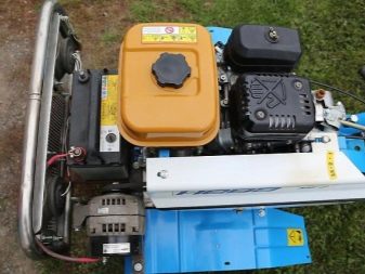
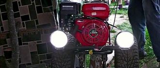
Headlights are placed on large walk-behind tractors. The generator has enough power for the installation of equipment and the operation of devices. To install the headlights, you can purchase a lighting device or make your own from an auto parts store.

To do this, you need to buy an element for the headlights. If the house has a moped, a car that has spare headlights, then they can be used for installation on a cultivator. Then you need to prepare the wire and the switch.
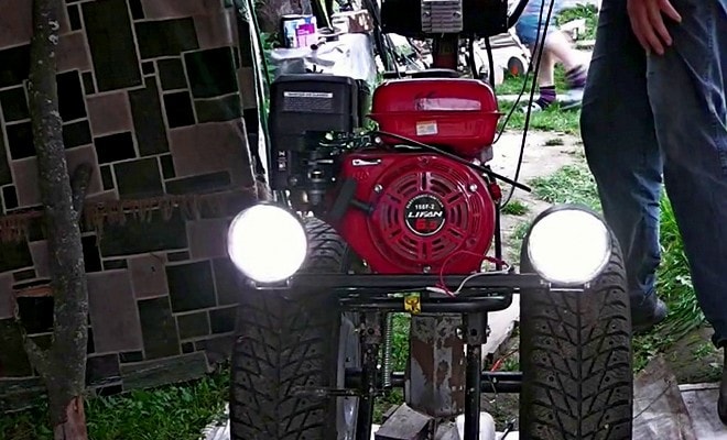
The first step is to install a switch. Then install the headlight on the steering column or on the front of the motor and mount the wiring. If the unit has holes for connecting the headlight, then it must be connected to it. Then the cord is connected to the switch, and from it they lead to the headlight. After that, the wiring is connected to the steering column using insulating tape and a prepared clip.
Will you be able to independently install (change) the walk-behind tractor generator, or would you prefer to turn to professionals for help?
How to make a headlight for a walk-behind tractor?
As a lighting on a walk-behind tractor, many owners of special equipment install headlights of domestic and foreign cars. This option is expensive and unreliable. There is not enough outgoing light, and the system itself will not last more than a few months. Alternatively, they develop a headlight for a walk-behind tractor with their own hands, which allows you to get the necessary lighting and equipment power.
Step-by-step instructions for making:
- Purchase an old, inexpensive headlight. Equipment from Soviet cars is suitable.
- Remove the glass protection and other plastic fasteners from the device.
- Pour the dummy headlight using plaster, for which the finished material is poured into the device and remains until completely dry. After that, you can remove the cast, preserving its integrity.
- The resulting template is applied in three layers of fiberglass, each time treating the material with epoxy resin. After processing, the future headlamp must dry under vacuum.
Many owners install the headlights of domestic cars as lighting on a walk-behind tractor
- Then they start making glass on their own. This will require an oven, special slats and fiberglass. It is necessary to make a platform from the slats, which is placed in a preheated oven up to 180-200 C °, where fiberglass is placed without a protective film.
- When the material begins to deform, it can be pulled out and applied to the finished workpiece. After pouring out the mold, it is necessary to place the future headlight in a vacuum.
- After complete cooling, the product is sanded with sandpaper.
- The final stage is the installation of electrical equipment, installation of the lamp.
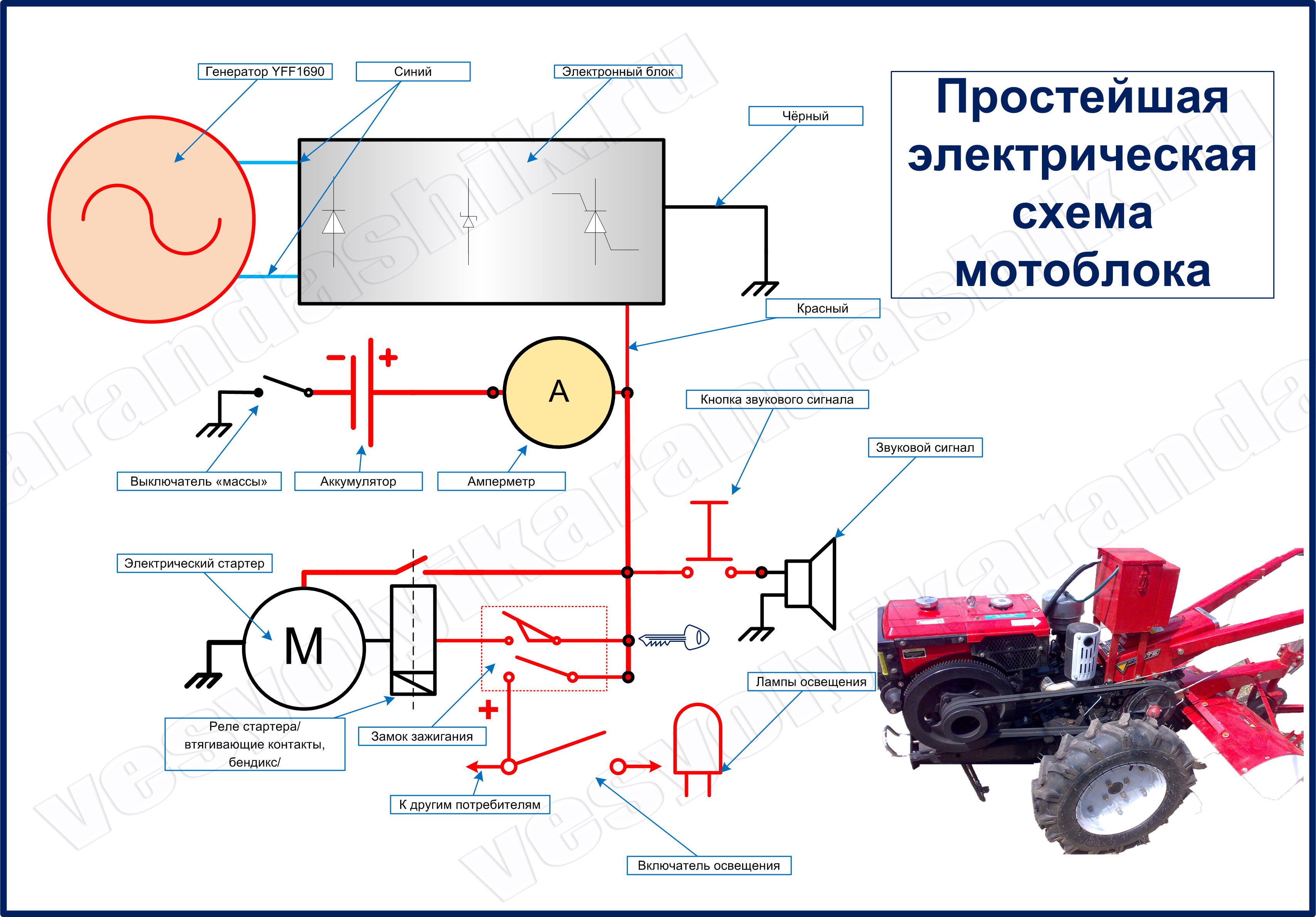
Electrical diagram
The headlight connection diagram is quite simple and consists of only three main elements:
- a power source, including an ignition, generator, or battery;
- power switch - a simple button that breaks and turns on the power supply circuit for the lamp;
- a lamp holder to which wires from a power source are connected through a switch.

A fairly simple scheme for connecting a headlight to a walk-behind tractor For greater reliability, all wires are placed in a special corrugation. The material protects the electrical wiring from damage and allows you to fix the equipment in such a way that it does not interfere with the use of the walk-behind tractor.
Necessary tools for the job
Before starting work, it is necessary to prepare all materials, including wiring, headlight, corrugation, and also assemble a set of tools:
- soldering iron;
- screwdrivers and wrenches;
- nippers and stationery knife;
- electrical tape and heat shrink tubing;
- electric drill and fixing materials.
Where to begin?
Based on the magnitude of the required loads for the simultaneous switching on of the devices, all the main elements are selected.
Optimum performance is achieved by matching the power of the petrol and electric engines.
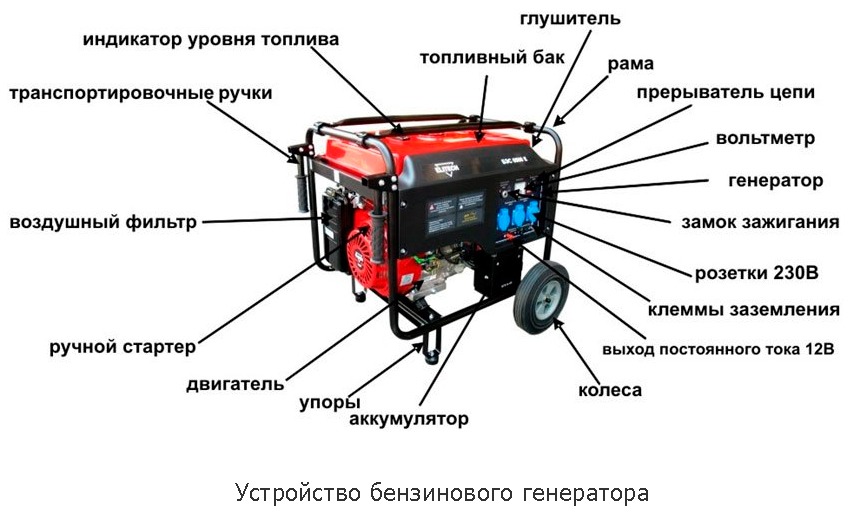
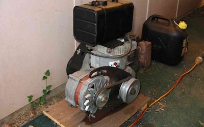 To obtain a single-phase current of 220 V, a two-stroke gasoline engine is suitable, and if you plan to obtain higher powers, then the choice should be stopped at a four-stroke. Fuel consumption will depend on the engine selected. In addition to the main task - energy generation, it is necessary to provide for a system of noise suppression, lubrication, ventilation, installation of an exhaust pipe for removing gases. You will have to buy wheels to ensure the mobility of the device. The casing can be made of metal or plywood.
A gas generator based on a two-stroke gasoline engine will help out if you need a short-term connection. When work is required for a long time and with a heavy load, it is better to make a generator with a four-stroke gasoline engine.
The control panel must have a voltmeter, a circuit breaker button, grounding terminals, and sockets for using the generated energy.
It makes sense to self-manufacture a gas generator when you have unused engines from old devices. You can, of course, buy all the components specifically for these purposes, but you will not be able to get big savings - the cost of the components may even exceed the price of the finished factory model.
In practice, motorcycle or car engines, motors from mowers, chainsaws and other devices are often used.
How to choose a generator for a household walk-behind tractor?
In the modern electrical appliance market, you can find a huge selection of generators designed for installation exclusively on walk-behind tractors. A wide range of products sometimes plays a cruel joke with novice farmers, as a result of which an inexperienced owner of an agricultural machine buys a factory generator that is not suitable for his walk-behind tractor.
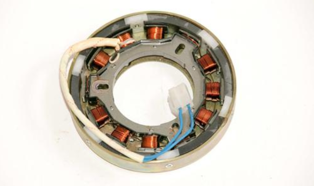
To avoid mistakes, one very important rule should be adhered to - the selected generator for the walk-behind tractor must have power. exceeding the total number of capacities of all loads that affect the walk-behind tractor during its operation
Observance of this factor when choosing a generator will allow the unit to operate stably under a voltage of 12 Volts, eliminating the risk of a short circuit or sudden voltage surges.
Often, farmers buy and install car generators on their walk-behind tractors. This solution fully justifies itself only if the farm uses a heavy walk-behind tractor with high power. For light and medium-sized agricultural units, it makes no sense to purchase such generators due to their high cost.
Organization of auto-switching
Not everyone will like to change the position of the circuit breaker with their own hands in the event of a power outage. In order not to have to constantly monitor when the current stops flowing from the mains, it is worth organizing a simple auto-switching system. With its help, as soon as the gas generator is started, it will be possible to immediately organize the transition to the backup source.
To mount an automatic switch switch system, you will need to stock up on two cross-connect starters. They are called contactors. Their work involves two types of contacts:
- power;
- normally closed.
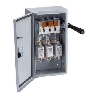
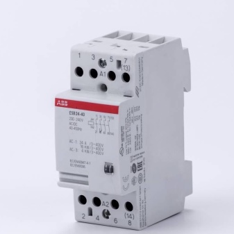
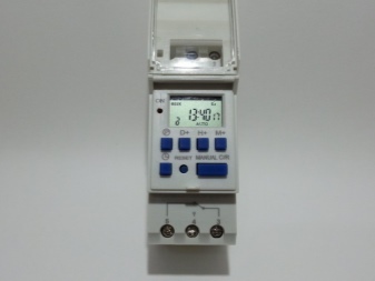
Additionally, you will need to buy a time relay if you want to give the generator a few minutes to warm up before starting work.
The operating principle of the contactor is simple. When the supply of electricity to the external line is restored, its coil blocks access to the power contacts and opens access to the normally closed ones.
The loss of voltage will lead to the opposite effect. The device will block the normally closed contacts and start the time relay. After a certain time interval, the generator will begin to generate electricity, supplying the required voltage. It will immediately be directed to the contacts of the reserve course.
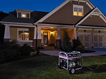
This principle of operation will make it possible to timely organize the blocking of contacts of the external network and ensure the supply of electricity by the mobile station. As soon as the voltage supply from the line is restored, the coil of the main starter will turn on. Its action will close the power contacts, and this will lead to an automatic shutdown of the generator.

For information on how to safely connect a gas generator, see the next video.
Basic connection tasks
When wiring, the following indicators must be taken into account:
- the need for automation;
- location in terms of economy and safety;
- stock selection;
- the frequency of network outages;
- power consumption including losses.
It is important to create a suitable connection diagram for a gasoline generator. Process automation is expensive and requires qualified maintenance
Manual connection for a private house is the most gentle mode. Such switches are produced in two types: a rocker switch (old model) or reversible (three-way). You can find out more about them below. Partial automation is also used, because semiautomatic devices are inexpensive. Regardless of the chosen method, you need to monitor the operation of the system
Automation of the process is expensive and requires qualified maintenance. Manual connection for a private house is the most gentle mode. Such switches are produced in two types: a rocker switch (old model) or reversible (three-way). You can find out more about them below. Partial automation is also used, because semiautomatic devices are inexpensive. Regardless of the method chosen, you need to monitor the operation of the system.
How to make a generator on a walk-behind tractor - just about the complicated

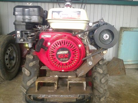
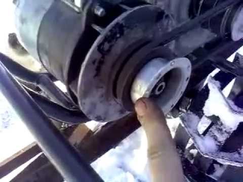
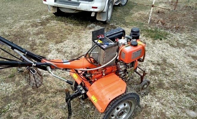
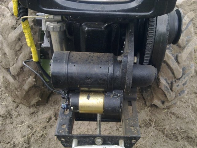
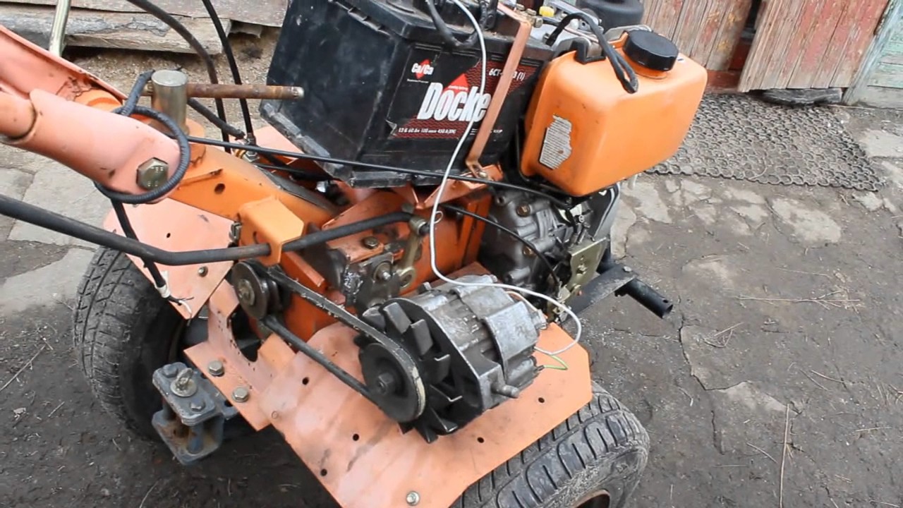
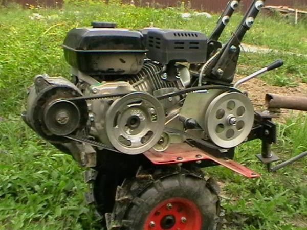
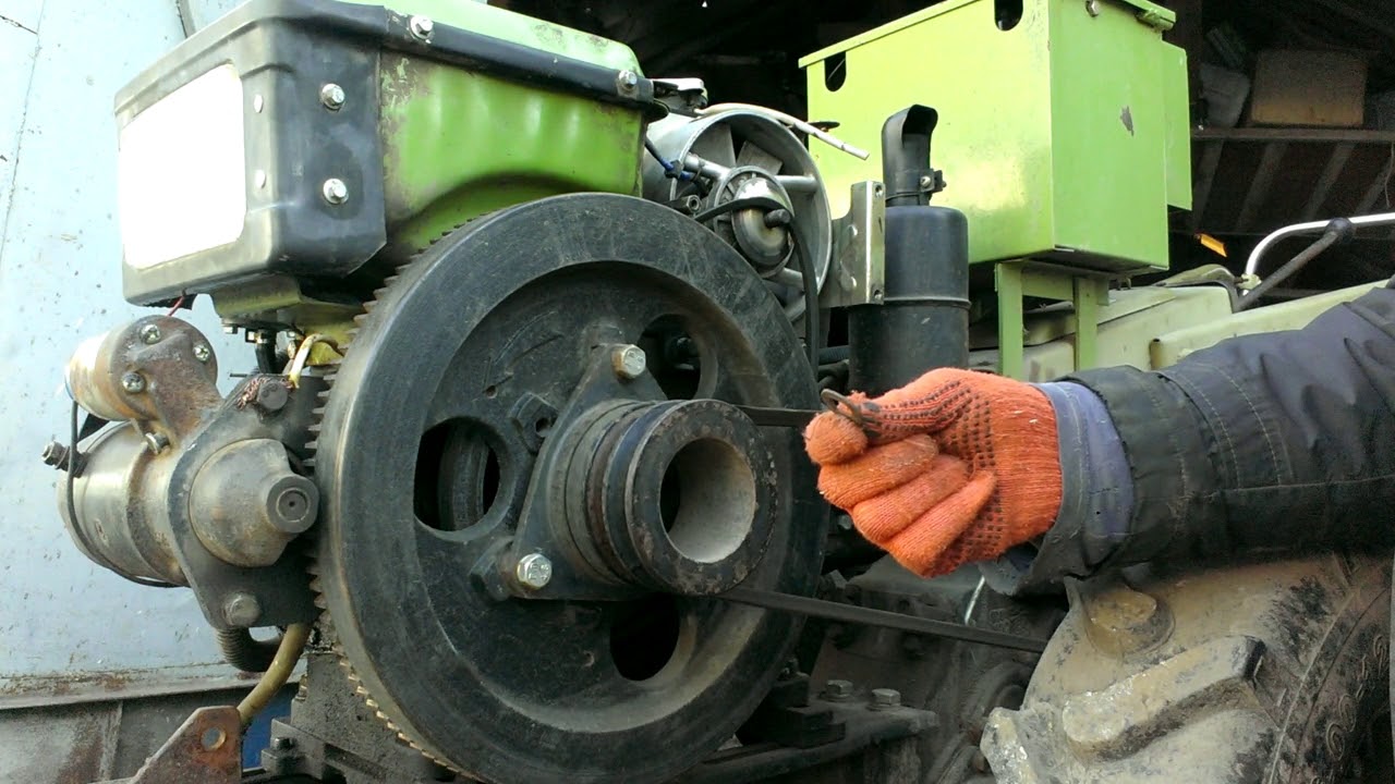
- First you need to install an electric motor on the walk-behind tractor frame. It is best to use a pre-made frame for this, screwed to the unit frame with screws. Place and fix the electric motor in the frame so that its shaft and shaft and the shaft of the standard motor of the walk-behind tractor are located strictly parallel to each other;
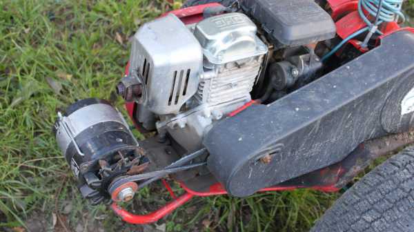
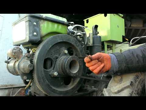
- Next, you need to install 2 pulleys - install one of them on the shaft of the gasoline motor of the walk-behind tractor, and the second on the shaft of the electric motor used. An important role for the proper operation of the entire system is played by the correctly selected diameter of the used pulleys - the speed of the electric motor depends on these dimensions. In order for the generator to work without malfunction, the diameter of the pulleys must be equal to the nominal diameter, which is indicated on the packaging of these parts. It is even better if the real diameter of the pulleys is 10% larger than the nominal one;
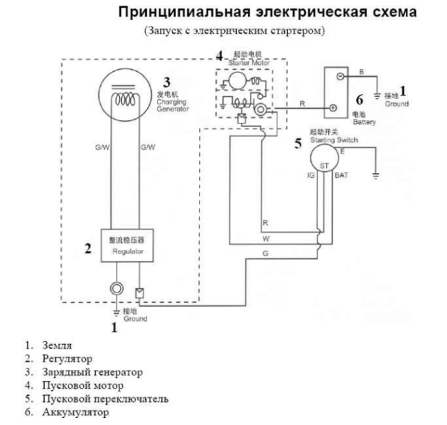
- Having finished the mechanical assembly of the generator, you can proceed to connecting it to the walk-behind tractor. To do this, use the wiring diagram above.
A homemade generator from an electric motor does not require special care. However, to extend the life of the device, a number of rules should be followed.
When operating a walk-behind tractor, pay attention to the following nuances:
- if you find that the electric motor installed on the walk-behind tractor has become very hot, then replace the standard motor capacitors with elements with a lower capacity;
- the voltage of the capacitors installed in the electric motor is of great importance. The best option for work is considered to be capacitors with a voltage of at least 400 volts. If this indicator is lower for standard electric motor capacitors, then replace them with suitable elements;
- try to operate the walk-behind tractor with an installed generator in dry weather, as moisture that can get into the electric motor will inevitably lead to a short circuit inside the electrical system.
By adhering to the listed rules, you will prevent damage to your homemade generator and significantly extend its life.
The above methods are suitable for the manufacture and installation of generators on Neva walk-behind tractors, as well as agricultural machines of other domestic and foreign equipment manufacturing companies.
How to choose an electric motor
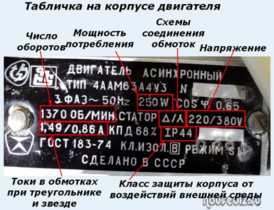
To eliminate errors at the project stage, it is necessary to pay attention to the design of the purchased motor, as well as its electrical characteristics: power consumption, supply voltage value, rotor speed. Asynchronous machines are reversible
They are able to work in the following mode:
Asynchronous machines are reversible. They are able to work in the following mode:
· An electric motor when an external voltage is applied to them;
· Or a generator, if their rotor rotates a source of mechanical energy, for example, a water or wind wheel, an internal combustion engine.
Pay attention to the nameplate, the design of the rotor and stator. We take into account their features when creating a generator
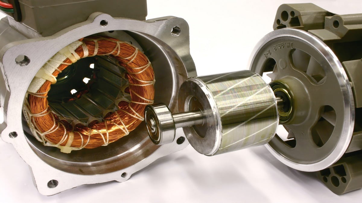
What you need to know about stator design
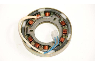
He has three insulated windings wound on a common core of the magnetic circuit for power supply from each voltage phase.
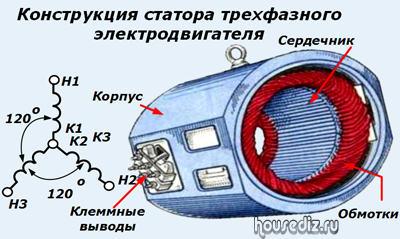
They are connected in one of two ways:
1. A star, when all ends are gathered at one point. At the 3 beginning and the common terminal of the ends, voltage is supplied through four wires.
2. Triangle - the end of one winding is connected to the beginning of the other so that the circuit is assembled in a ring and only three wires come out of it.
In more detail, this information is set out in the article on my website about connecting a three-phase motor to a household single-phase network.
Features of the rotor design
A magnetic circuit and three windings are also created on it. They connect in one of two ways:
1. through the contact terminals of a motor with a wound rotor;
2. short-circuited by an aluminum insert in the squirrel-cage wheel - asynchronous machines.

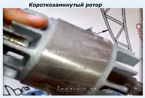
We need a squirrel cage rotor. All circuits are designed for him.
The phase rotor design can also be used as a generator. But it will have to be redone: we just shunt all outputs together with short circuits.
How to take into account the electrical characteristics of the engine
The generator will be affected by:
1. The diameter of the winding wire. The heating of the structure and the amount of applied power directly depend on it.
2. Estimated rotor speed, indicated by the number of revolutions.
3. The method of connecting the windings in a star or delta.
4. The amount of energy loss, determined by the efficiency and cosine φ.
We look at them on the plate or calculate them by indirect methods.
