Step three: prepare the bed for the mini-milling cutter
Firstly, here it was necessary to cut off two pieces of a square profile 20 × 20 mm, 20 cm long and two more - 25 × 25 mm, 2.5-3 cm long. This can be done both on a machine and using a simple grinder. It seemed to me more convenient to use the machine.
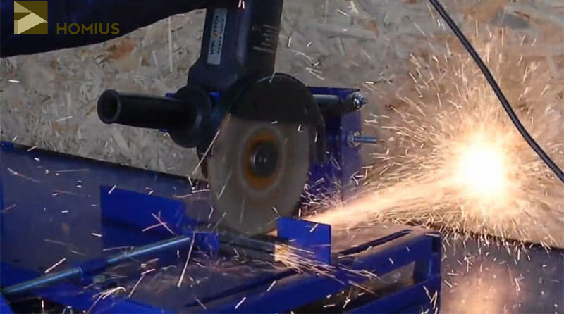 We cut a metal square profile into pieces of the required length
Assembly of the bed
Now the welding machine comes into operation. We put the base on the table. We fix guides on it on tacks - longer sections of a square steel profile. Do not weld seams immediately. This will lead to the fact that they will lead, and all the work will have to be redone. To begin with, you just need to grab a couple of points - on one side and the other.
Shorter and wider sections of the square profile are fixed on the bracket (also on tacks). After that, they are put on the rails so that it is clear if the racks are not skewed. If it is difficult to understand the progress of work from words, you can look at the photo below. Here it will immediately become clear how to assemble the base.
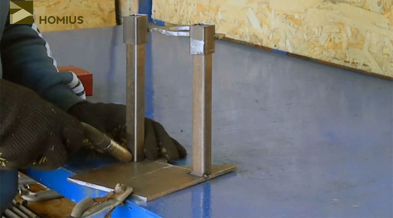 This is how the bed should look like. So far she only holds on to potholders
Having found out that everything is in order, you can completely weld the seams (without removing the bracket from the guides). After that, you can proceed to work with the bracket clamping system.
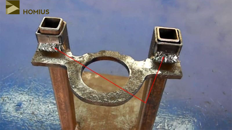 The seams are thoroughly welded, after which the bracket can be removed from the guides
We bring the bracket to mind: we mount the clip for the grinder
In order to be able to clamp the grinder in the bracket ring, we cut an opening in its upper part, and weld on a long nut on one side and a short nut on the other from the end. At the same time, we drill a short (simple) nut so that the bolt freely passes through it.
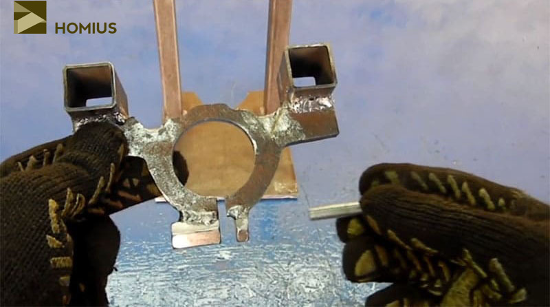 Bracket clamping mechanism ready, can be used
Additional fixings are now needed. Their role will be played by metal corners, which I cut from a galvanized sheet. They will be attached to the bracket itself by welding, and to the grinder they will be fixed with bolts screwed into the seat of the handle.
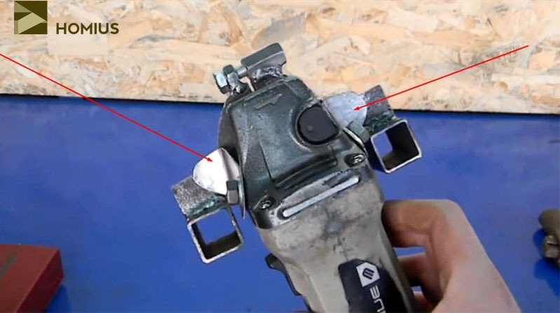 This is what the mounting angles look like. They are not yet welded to the bracket.
Due to the fact that the bracket moves freely along the guides, it was necessary to think over the locks. For this, in holes were drilled in the square profile for bolts in which a suitable thread is cut. Flaps were welded to the bolt heads for ease of rotation. It turned out to be a kind of "lambs".
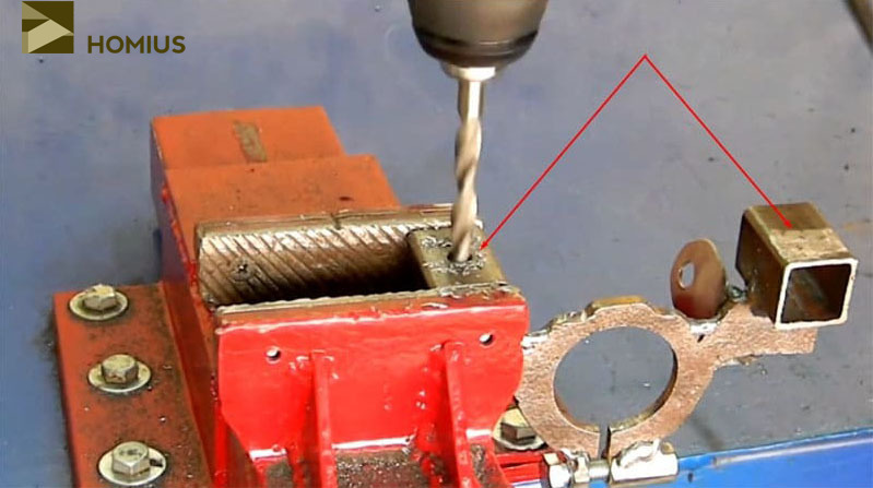 We drill holes, and then we cut a thread in them
Step-by-step instruction
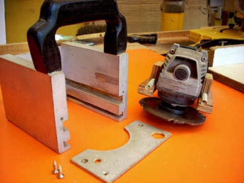
Before the master begins the direct assembly of a homemade router, you will have to spend time to make the components and parts of the bed. To do this, the master:
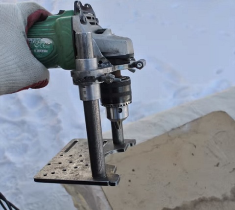
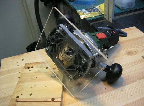
- cuts a steel sheet and cuts out a rectangular blank from one part - a sole is made from it. On it, the central axis is outlined between the two lateral (short) sides. Then a semicircular hole with a diameter of 1-3 times the length of the side is drawn with the center of the circle located on the axial perpendicular, at a distance of 1.5 cm from the end of the side. Along a line parallel to the lateral side from the points of the semicircle diametrically distant from the center, two segments of 1-1.5 cm are drawn to the sides. Then, from them, another segment at an angle of approximately 60o to the lateral side. The result should be a dome-like figure resting on a flat trapezoid.
- The workpiece is clamped in a vice and, with the help of a grinder, is cut along the lines drawn.The sharp edges are then sanded for safety. The sole is ready.
- Now a suspended "braid" for the grinder is being designed. With the help of a drill and a special annular nozzle, a circle is drilled out of a metal workpiece, calculated according to the shape and size of the grinder - it will lie on this braid, fixing itself from below with a chuck with a cutter.
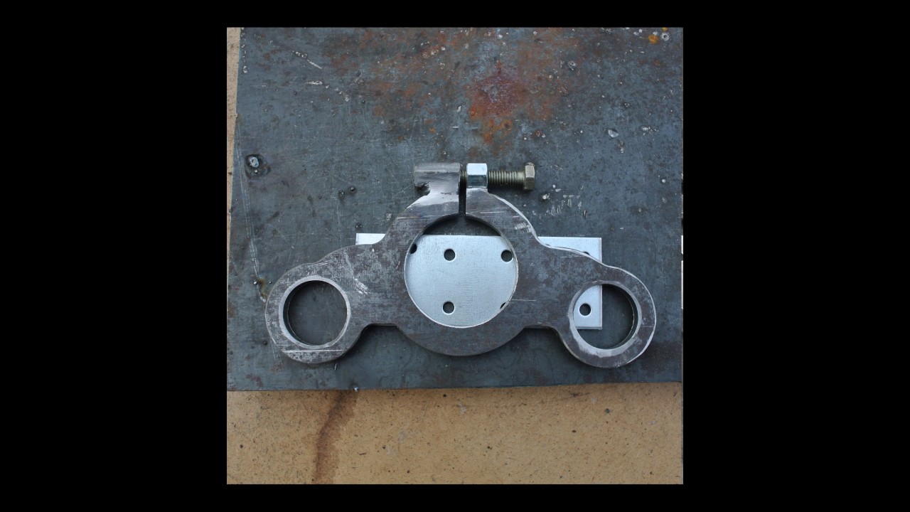
- Then, before cutting out the part, it is recommended to prepare a stencil from cardboard. In shape, it resembles a "circle with triangular ears", which are then grinded at the circle and along the edges. After that, the stencil is superimposed on the metal of the workpiece, so that the hole for the grinder's chuck is located in the center of the circle. After that, the metal is cut using a stencil.
- Supports of the same height are cut from one profile (smaller in height), which are welded parallel to each other at an equal distance from the central axis of the sole.
- From the second profile (the cross-sectional height of which is greater), "cubes-sleds" of the same size are cut out, which freely "slide" along the "rails" welded to the sole.
- The "ears" of the workpiece are sawn off and welded to the sliding cubes so that it can slide down and up along the guides on them.
- In the upper part of the workpiece circle, another slotted hole of 2-3 mm is sawn, after which it is welded onto it by welding: on one side of the resulting arc - a nut, and on the other - a screw. This is done in such a way that when screwing in, the circle decreases in diameter, and the grinder with the chuck is tightly fixed in it horizontally.
- To fix the grinder on the "carriage" obtained from the workpiece, additional oval "ears" are cut out of the metal, in the upper part of which holes are drilled, the size of which coincides with the side bolts on the grinder. The lower part is folded at a 90 degree angle in a vice. After that, the ears are welded to the carriage. For ease of use, instead of a bolt, you can screw a double-sided holder into one of the "ears", onto which the handle from the grinder will be screwed.
- In each of the cubes, a slide is also drilled through a hole and a nut is welded onto it, which, in combination with the fasteners, will lock the carriage at the desired height.
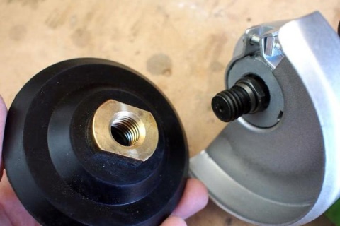
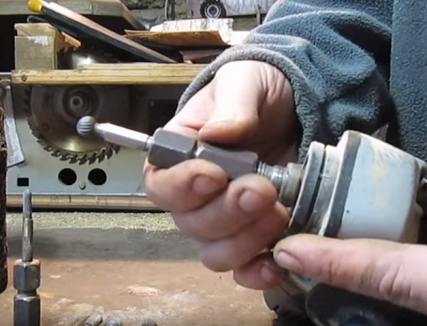
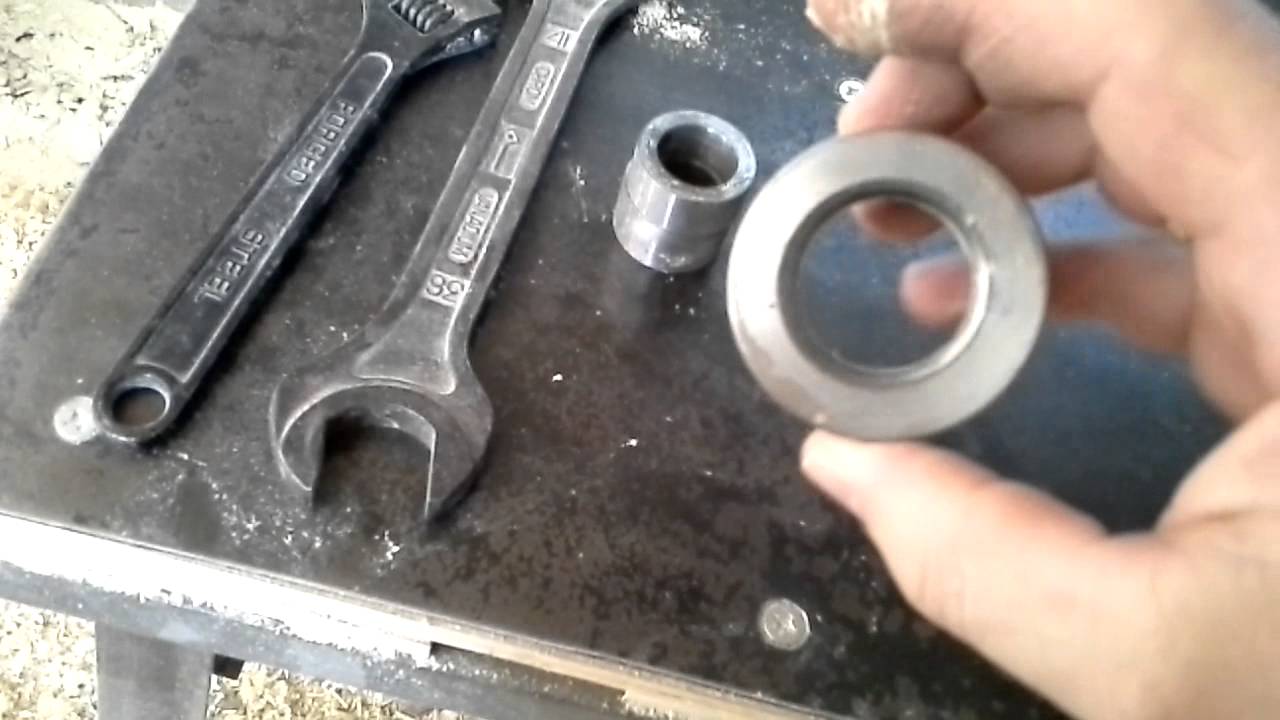
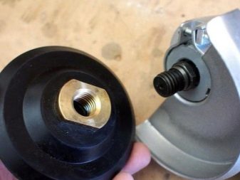
- Manufacturing of a collet for a cutter. An old chuck is taken from a drill and in the hole along the shaft, with the help of a tap, a thread is cut under the axis of the grinder. The thread of the tap is selected according to the pattern of the nut that secures the grinding disc to the shaft.
- The details of the resulting structure are sanded and blown. It is recommended to paint the frame for aesthetics and to protect the assemblies from dust.
After the assembly is completed, the grinder is placed on the carriage, fixed with a disk clamp. Then the cartridge is installed, the cutter is mounted in it, and the installation is fixed in height with clamps on the "slide".
Thus, using this model and making a milling bed in a home workshop, the master gets at his disposal a specialized attachment for the grinder, which will perform all the necessary woodwork and will in no way be inferior to industrial, often expensive samples.
Required materials and tools
Before proceeding with the direct work, you should purchase the required materials and tools. A do-it-yourself milling machine from a grinder can be made if you have:
A suitable electric drill or grinder
When choosing, special attention is paid to the power of the installed electric motor. The structural element of the device, which is responsible for fixing the nozzle, must be strong and provide reliable fastening at the time of operation.
Level and angle required to improve the accuracy of the product.
Set of wrenches.
Drill with a wide range of different drills
To fix the main elements, you will have to create special holes, for which a drill is suitable.
Screwdrivers.A set of screwdrivers is required to work with various fasteners.
Electric jigsaw, as well as special saws for wood. They are used for working with plywood and other wood, allowing you to achieve higher quality when cutting.
Thick plywood or thin sheet metal is required in order to make a lamellar router from a grinder. They are used to fix the main element at the time of its application.
A welding machine is also required when carrying out such work. An example is when you have to work with sheet metal when creating a base.
Fasteners are also required to create the device. The most commonly used bolts, nuts and screws, as well as clamps of various materials.
Sandpaper to obtain the required surface quality. When using plywood, it has to be reworked, since even minor defects can complicate the milling process.
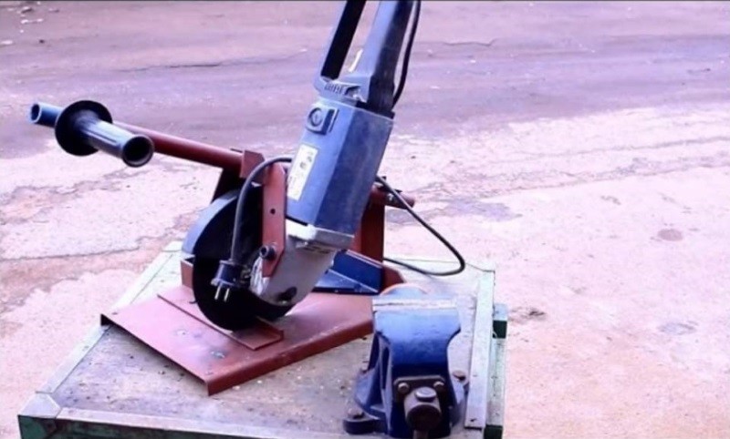
Particular attention should be paid to the choice of a grinder, which is used as a basis for creating a tool.We will call the main requirements:
- The structure must be in good technical condition. Even minor defects can lead to reduced performance and functionality.
- Too little power becomes the reason why the range of application of the router is significantly reduced. Low-power versions begin to warm up during long-term operation. Overheating will damage the electric motor.
- Large versions are suitable for the router. Due to this, the main elements can be conveniently fixed. However, if too heavy versions are used, the milling process can be complicated.
In addition, the work requires a standard set of locksmith tools. Almost everything you need can be found in every home workshop. The collet for the grinder is also made by hand from metal.
How to choose the power of equipment for a wood router for home workshop
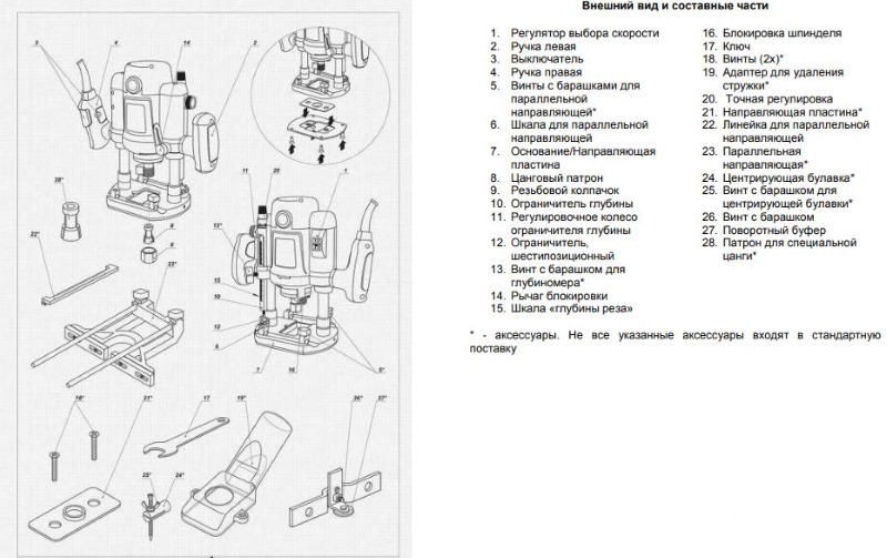
The hand router is specially designed for work in small workshops or on the road. It is difficult to process large batches of lumber on it, such a machine simply cannot withstand the volume of work. Bulky workpieces are easier to process on stationary machines.
For home, household use, low-power machines are quite suitable. For example, 400 watts is sufficient for small jobs and softwood drilling. Machines of this power can be used for grooving. The price of hand-held wood cutters is not high, however, the set of functions is very limited.
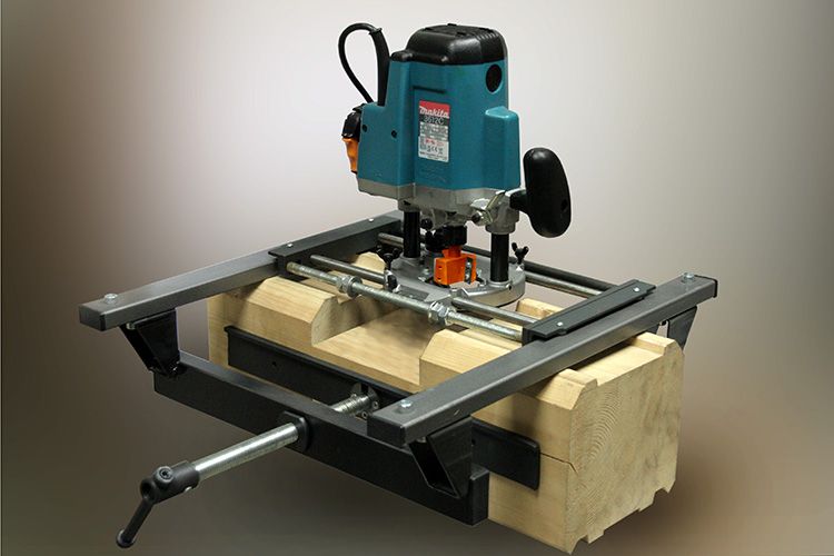 If you plan to expand the specifics of processing, then it is better to opt for a model with a power of at least 1 kW
With such equipment, you can easily work on any type of wood. For everyday needs, this is quite enough. For professional use, it is recommended to choose a machine with a power of at least 1.5 kW. It is not always possible to buy such a milling machine for wood, because the price can reach several tens of thousands of rubles. On such a device it will be possible to process large volumes of wood, as well as plastics, soft alloys, such as aluminum, it will "eat" any type of cutters. Remember that the time it takes to complete the task depends on the power.
The spindle speed is a very important characteristic that affects the price of a wood milling machine; this parameter should be paid attention to when choosing equipment. Processing dry or damp wood of different densities is most effective at certain speeds
The dimensions of the working platform and the distance from the spindle axis to the working table top determine the dimensions of the workpieces being processed. Choosing the right spindle for a wood milling machine determines the accuracy and depth of machining of the part, as well as the ability to select the right milling cutter.
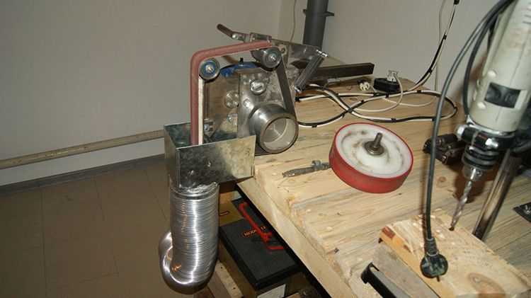 Dust extraction - when processing wood, an exhaust snail is an irreplaceable thing. Sometimes for such purposes ordinary vacuum cleaners are used, which are attached at a certain angle to the frame.
Dimensions and weight of the machine - a desktop compact model is suitable for an amateur, which is installed on a workbench, and after use is removed to the pantry. If you have a workshop, it is more expedient to assemble a full-fledged wood milling machine on a bed with your own hands. If work is planned on a construction site, choose a hand-held milling cutter.
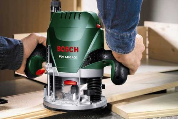
Much more convenient to use is a submersible milling cutter, the drive motor of which is mounted on special guides and during processing can move along them along with the working nozzle. The design of the submersible milling cutters also has a special spring, which provides the lifting of the working nozzle after processing with its help.
If in the process of purchasing top-type milling cutters you choose which one is better, then you should definitely pay attention to submersible models that are perfect for both professionals and beginners.
Step one: preparing the material, getting to work
First of all, I needed to dissolve the I-beam by cutting out the central part from it. It is she who will become the basis of our design. It is not difficult to do this, however, for those who rarely deal with angle grinders, I will say that it is advisable to use protective equipment - gloves, glasses, a tight apron.
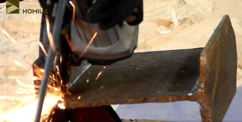 Clamping a piece of an I-beam in a vice, cut out its central part
It is clear that the section of the I-beam I found near the garage was covered with rust, therefore, holding it in a vice, I completely cleaned the surface from corrosion using a metal brush-circle on a grinder. After that, the metal could already be used for its intended purpose.
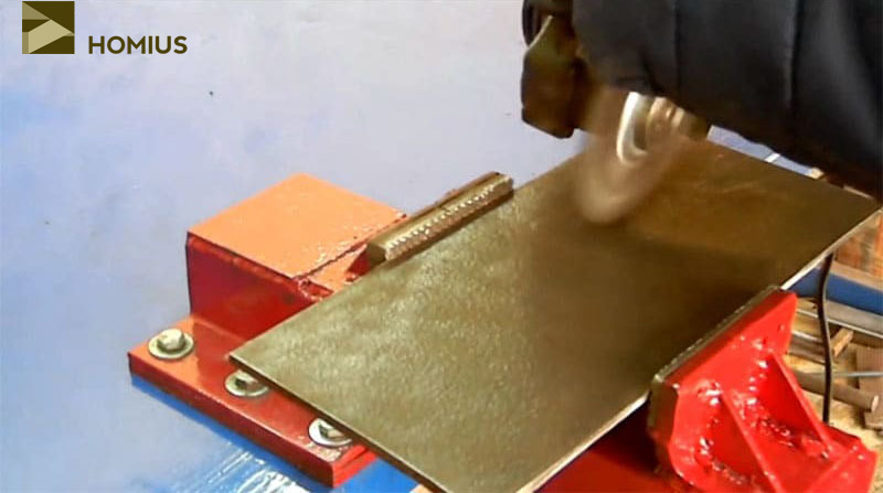 All traces of corrosion must be carefully removed
What components and materials are needed in the work
To create the strength components, steel corners and pipes with a minimum wall density of 2 mm are used. Their connection options: welding or screws. All metal components are primed and painted to protect against corrosion.
For countertops and some other elements, durable chipboard and plywood classes are suitable. They are resistant to moisture, temperature fluctuations and other hazards.
Electric motor
It is needed when you plan to create a small CNC router. Its most important parameter is power. It is better to use a device for 1100 watts. It will allow you to use a variety of cutters.
You can also use a motor from hand-held power tools: a drill, hammer drill or grinder.
engine's type
For optimum performance, the machine can be based on an asynchronous unit with three phases. Then the milling cutter will be connected to the network, guided by a special scheme. It uses the "star-triangle" algorithm. As a result, the engine starts smoothly and allows the machine to operate at maximum power.
If such a motor is connected to a network with one phase, then it will lose 50% of its efficiency. If the network does not allow this type of connection, then a 1-2 phase motor is used.
Required tools
A very dense piece of cast iron or stainless steel is used to make the bed. A special shaft is attached to the support from above. Its upper zone rises above the table through a hole. In all such machines, the shaft lifting height can be adjusted.
A spindle is mounted on top, equipped with a cutting tool. The industrial models use a solid cutting arsenal. The key types of equipment are: disc, knife and cutters of various shapes.
To carry out cutting strictly in a straight vector, a special guide bar is used. Due to a special fastening unit, it moves to the desired length. The quality of machining increases significantly if the dynamics of the spindle rotation is high.
Procedure
First, decide which milling tool you need - stationary or manual. Both the one and the other option have their own characteristics during assembly and operation.
Stationary
If you need a stationary milling machine, consider when designing it that its capabilities will depend on the power and rotation speed (number of revolutions) of the grinder's motor, as well as the area of the table for work (workbench). For processing parts made of small-sized fragile wood, a small grinder is enough, the motor power of which is 500 watts. If the milling cutter is to work with metal blanks, the power of the angle grinder engine must be at least 1100 watts.
The design of the router consists of such elements as:
- stable base;
- movable / fixed tabletop with lined rail;
- drive unit.
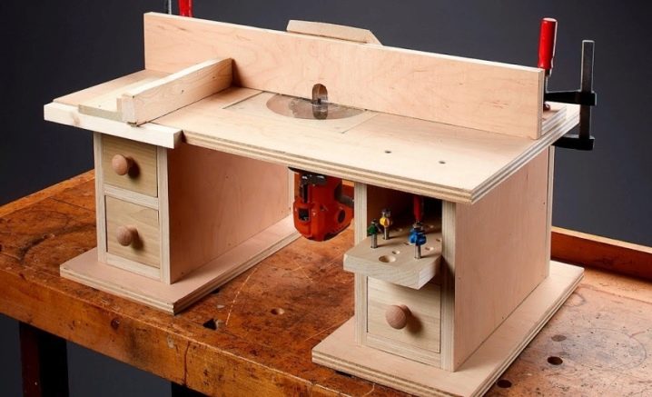
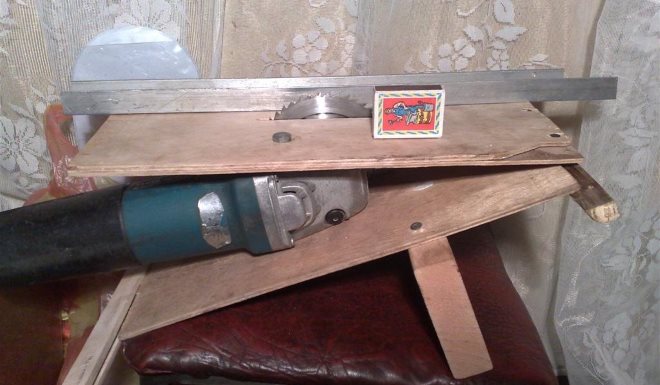
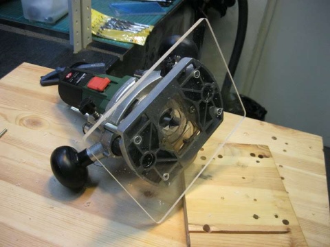
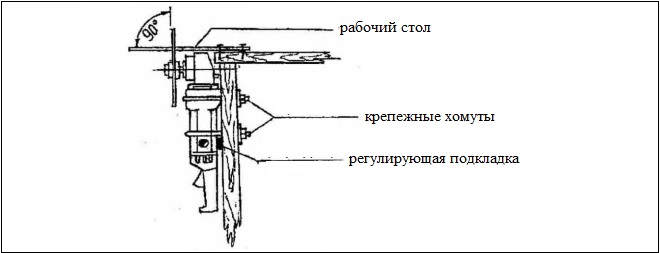
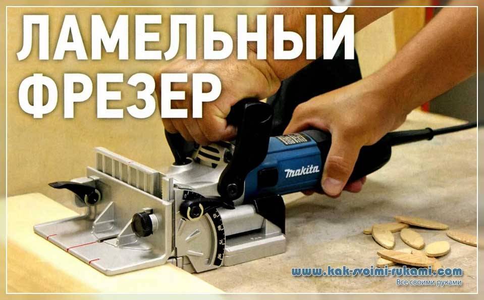
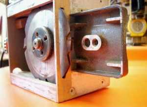
Lamellar milling machines are distinguished not by vertical, but by horizontal arrangement of the working cutter. There are 2 options for designing a homemade milling machine:
- fixed table - movable tool;
- movable worktop - fixed tool.
In the first case, for horizontal machining of a part, the procedure is as follows:
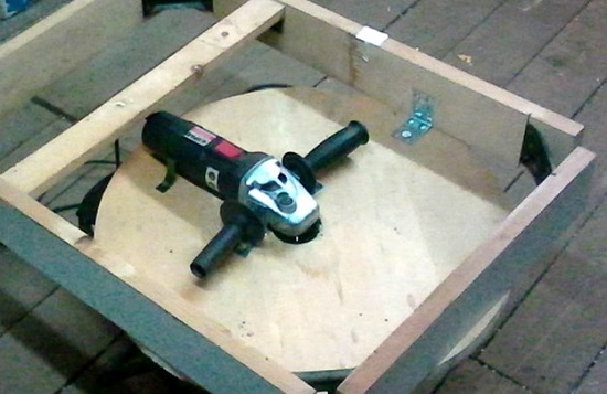
- fix the angle grinder to the plate vertically (the cutter attachment is horizontal);
- guides are installed around the table for moving the plate with the tool;
- the workpiece is fixed to the work surface.
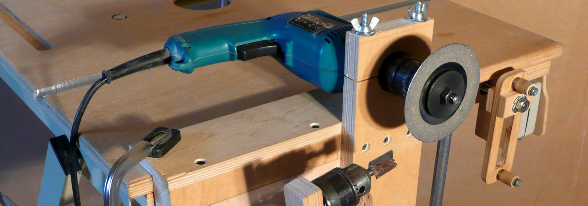
Thus, the processing of the fixed part is carried out with a movable tool. In the second case, you need to ensure the immobility of the grinder and the mobility of the working surface. To move the table top, a structure of guides is constructed under it with the possibility of fixing the position of the working surface. The angle grinder, in turn, is fixed on the vertical bed on the side of the workbench. When a machine with a vertical working attachment is required, the procedure is as follows:
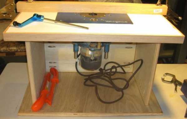
- assemble the frame from blocks of wood or corners, ensuring that they are rigidly fastened to each other (using welding or fasteners);
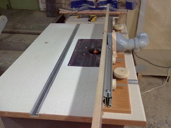
- attach a sheet of chipboard or plywood to the frame;
- make a hole for the angle grinder shaft - the diameter of the recess must exceed the corresponding indicator of the shaft cross-section;
- fix the tool inside the frame - using clamps or bolted punched tape;
- on the working surface of the table, build guides (from rails, strips, etc.) to move the part;
- sand and paint all surfaces;
- The toggle switch for turning on the tool for comfortable use can be fixed.
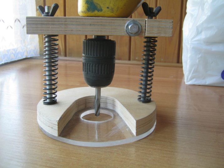
photos
All caps of self-tapping screws (bolts, screws) must be recessed and not protrude above the surface of the working area.
Please note that the guide rails must be removable; different workpieces require different positions. The most convenient way to fix them is to use self-tapping screws. The tool should be conveniently located and accessible for quick replacement of the working attachment (cutter, disc, etc.).

Manual
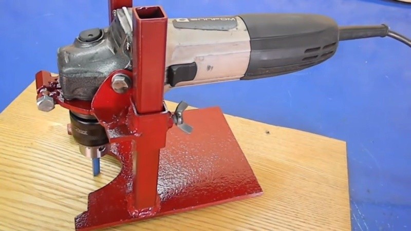
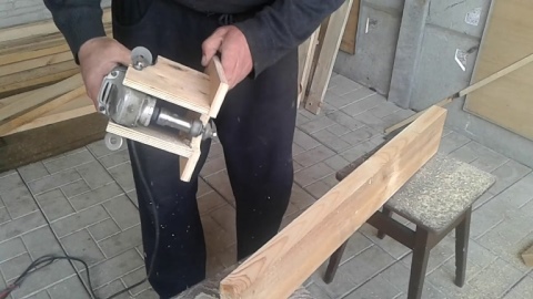
The easiest option is to convert the grinder into a hand-held milling machine. Please note that in this case, a reliable fixation of the workpiece is necessary - with the help of a vice or clamps, in order to exclude the possibility of vibration or shift of the workpiece. There are several ways to convert a grinder into a manual router. Here is one of them.
First, make the base base of the tool according to the drawings.
The ideal option would be a base made of a metal sheet of sufficient thickness and weight, because the mass of the base directly affects the stability of the device. Then make a fixing plate - a bracket to hold the angle grinder. The material is the same as at the base. You need to make a hole for the back of the tool, the one where the handle is. Cut out the blanks in the shape you want.
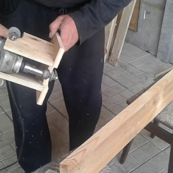
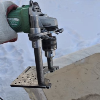
Weld sections of square pipes to the ends of the product - to move along vertically located guides.
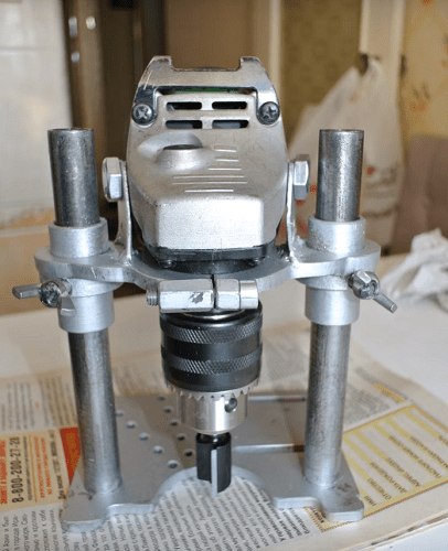
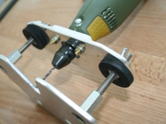
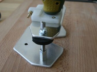
Longer sections of square pipes, but with a smaller diameter, will serve as guides. They need to be welded to the base. To increase the reliability of fixing the tool, you can make and weld a kind of "ears" from a metal sheet. To fix the tool at the desired height, you need to make a mount. You can weld 2 nuts, screw the threaded rods into them, onto which the wing nuts are welded. With the help of such a device, you can easily and quickly change and fix the required position of the tool.
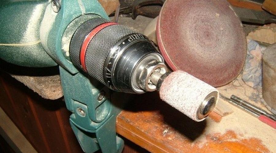
Now you need to install the drill chuck as an adapter for the working nozzle-milling cutter.
Pre-cut a thread inside it corresponding to the shaft of the angle grinder. Then screw it onto the shaft and fix the required cutter in it. Assemble the car. Fix it in the bracket.
Components and assembly algorithm
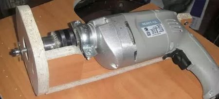
It is possible to make a milling machine from a drill, which almost every home craftsman has, but it should be borne in mind that such a device cannot fully replace the serial model. This is explained by the fact that the chuck of a conventional hand drill can rotate at a speed of 3000 rpm, while a serial mill is able to rotate the used tool at a speed of up to 30,000 rpm. In addition, the gearbox of a household electric drill is not designed for intensive loads that will quickly lead to a malfunction.
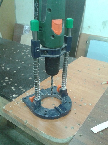
Vertical router from a drill
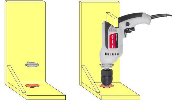
Diagram of the simplest vertical drill stand
Meanwhile, the simplest milling cutter, made from scrap materials with minimal financial costs, is able to successfully cope with many technological tasks. To craft your milling machine from an electric drill, you must find the following materials and tools:
- several pieces of chipboard or thick plywood;
- a clamp with which the drill will be fixed on the base of the device;
- bolts, screws and other fasteners;
- feather drill or drill bit with a diameter of 40 mm;
- standard set of locksmith tools.
Slat trims, pieces of plywood, metal corners - all this can be used to make a simple milling stand
The very process of assembling a homemade router is carried out according to the following algorithm.
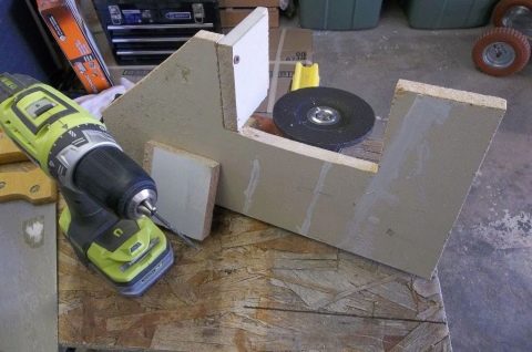
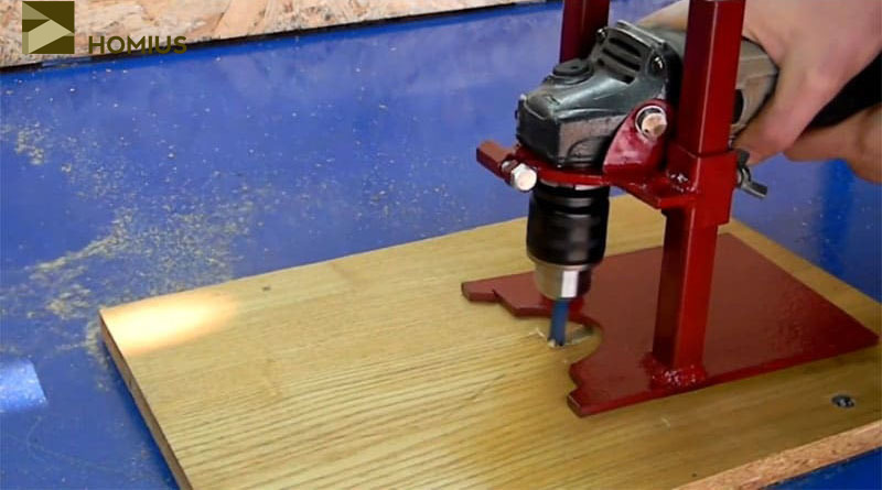
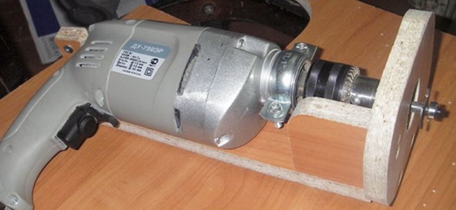
- The base of the future router is assembled from chipboard or plywood sheets, which includes a horizontal base and a vertical part on which an electric drill will be fixed. The dimensions of the chipboard or plywood sheets from which such a structure will be made are calculated depending on the dimensions of the electric drill used as the basis for a homemade machine.
- A hole with a diameter of 40 mm is drilled in the horizontal base of the device, which is necessary in order to provide access for the tool to the processing area.
- A clamp is attached to the vertical rack of the device with a bolt, in which the electric drill is fixed. In this case, the drill should be positioned so that the lower end of its chuck is a few millimeters from the horizontal base of the router.
- To make the position of the drill on the vertical stand more stable, a small wooden block can be fixed in its upper part, which will act as a stop.
Drill mounting options (click on the photo to enlarge)
Stand with height adjustment by means of a lever
How to make a milling machine of the above-described design more convenient and functional? To do this, it can be equipped with the simplest microlift, which will be responsible for moving the electric drill in the vertical direction. To manufacture such an elevator, you will need the following consumables and components:
- two metal rods that will act as guiding elements;
- platform (carriage) for fixing an electric drill, made of chipboard or thick plywood;
- threaded axle and nut, which will be responsible for moving the electric drill in the vertical direction;
- elements that ensure the fixation of the electric drill in the required position.
Column height adjustable with threaded rod
The principle by which such a homemade router works is quite simple and is as follows.
- When the threaded axis rotates, the carriage with a drill fixed to it moves in the vertical direction.
- After the electric drill and the tool fixed in its chuck are set in the required position, the carriage is fixed with fasteners.
Naturally, the entire structure of such a homemade router, whose work is well demonstrated by the video, must be fixed on a reliable base. The latter can be the surface of the desktop or workbench.
A machine made from an old electric motor
A home-made milling machine, with the help of which many technological operations are quite successfully performed, can be made without using an electric drill. In order to make such a device, you will need the following consumables and accessories:
- an electric drive motor, which can be used as an electric motor from an old washing machine and other household appliances;
- the chuck in which the used cutting tool will be fixed;
- an adapter with which the drive motor shaft will be connected to the chuck;
- sheets of chipboard or thick plywood for making the base and vertical guide of a homemade router.
Materials used
The grinder is considered a multipurpose device, on the basis of which various designs can be made. One of these devices is a router. Made from a grinder with our own hands, it only copes with simple cutting tasks. Such work will require the fulfillment of certain conditions, the main of which are to ensure good fixation of the tool in the plane of the plumb line and its movement relative to the plane of the workpiece.
To make a milling machine from a grinder, the following materials are required:
- Grinder or drill with a running motor.
- The components that will support the devices in the structure. They must be strong and reliable.
- Base for mounting the router: thick plywood or thin sheet alloy.
- Welder.
- Fastening components.
- The usual set of locksmith tools.
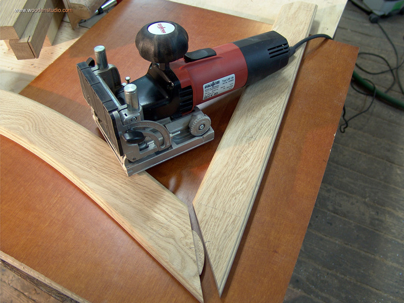
Cutting discs
They are made from tungsten carbide, which is highly durable. Depending on the cutting depth and the number of teeth, there are several types of cutting discs. To choose which disc to buy, follow these guidelines:
- With infrequent and short-term use of a circle and cutting a variety of wood, it is worth choosing a disc whose teeth are chamfered.
- When processing soft woods, a circle with straight teeth is used.
- Trapezoidal discs are best for cutting medium-density wood, chipboard and USB boards.

